 2021, Vol. 32


b Institute for Sustainable Energy, College of Science, Shanghai University, Shanghai 200444, China
With the rapid development and commercialization of new energy vehicles powered by lithium-ion batteries (LIBs), their recharge mileage has been considered to one of the concerns. To prolong the recharge mileage of the vehicles, further increasing the energy densities of LIBs is necessary through developing high capacity anode and anode materials [1-5]. The currently used anode material is graphite (372 mAh/g), which is insufficient for high energy density requirements [6, 7]. Therefore, the pursuit for the next generation of high capacity anode materials for LIBs has become a hot topic in the last several years. Among different types of anode materials, silicon with a theoretical specific capacity as high as 3579 mAh/g and lower work voltage (~0.2 V vs. Li/Li+) and its composite materials have drawn a great deal of interest. However, their huge volume expansion effect during lithiation/delithiation processes and insufficient electron conductivities have limited their practical utilization [8-12].
The volume expansion effect of silicon-based anode materials can be up to 300% (Si > 300%, SiO ≈ 150%, SiO 2 < 150%) during lithiation/delithiation processes, so that they would be collapsed and shed from the current collector or directly pulverized [13-15]. In addition, the expansion effect would cause significant degradation, decreasing the electrochemical performance and reducing cycle-life of the LIBs [16-20]. As a general observation, the initial coulombic efficiencies of the silicon-based anodes are generally low (< 80%), which makes them hard to be commercialized [21-23].
Currently, many efforts have focused on decreasing the expansion effect and improving the low conductivity of the silicon-based materials. The typical approach is to reduce the particle size of silicon-based materials to nanometer size including nanospheres, nanowires, nanotubes, yolk structure, etc. [24], [25-28]. For example, Zhang et al. [29] relieved the volume expansion effect of the silicon-based anode by cracking PPP and PVC to coat silicon. Jung et al. [30] improved the cycle-life of silicon-based anode by preparing thin-film amorphous silicon using a low pressure chemical vapor deposition (LPCVD) with Si2H6 as the source gas. Cui et al. [31] prepared a carbon-silicon core-shell nanowires as high capacity anode for LIBs, obtaining a high specific capacity of 2000 mAh/g. Table S1 (Supporting information) summarizes the selected researches on synthesis and modification of silicon-based materials in recent years [32-36].
The other approach for overcoming the negative effect of electrode expansion during lithiation/delithiation processes is to develop new adhesives to reduce the cracking and chalking of the electrode materials particles. As identified, the conventional polymer polyvinylidene fluoride (PVDF) is not good enough in generating sufficient adhesion in the silicon-based electrodes due to its weak Van Der Waals force, which makes it easy for silicon to fall off the current collector. Therefore, various polymer materials such as sodium carboxymethyl cellulose (CMC), polyacrylic acid (PAA), alginic acid (AlG), modified natural polysaccharides have been explored as the adhesives. Other adhesive strategies including self-healing polymers, polyrotaxane with sliding ring movement, polymers with ion conductive groups, and in-situ cross-linked polymer networks have also been proposed to effectively improve the cycling performance of silicon-based LIB anodes [37-39].
In this work, SiO is explored as the silicon source with much lower expansion effect than Si. Electrostatic spinning technology, as a methode for preparing nanowires, is used to encapsule the silicon source into the carbon fibers (CNF) to form a SiO/CNF composite for the first time. As tested, the carbon fibers can significantly improve the electrical conductivity of the composite materials, and its reconstructed heterostructure with rich elasticity can effectively accommodate the expansion effect of the anode. The electrochemical performance in this paper reveals that the composites obtained by this method can significantly improve the performance of silicon-based anodes, demonstrating their promising in practical applications in lithium-ion batteries.
In a typical synthesis, 5 g of SiO (average particle size = 75 μm, marked as u-SiO) and 0.05 g of ascorbic acid were added to 40 mL deionized water for ball milling at 450 r/min for 4 h. After ball milling, the precursor solution was dried at 60 ℃ for 12 h to obtain a sample as b-SiO. Afterwards, 0.2 g of this b-SiO and 0.8 g of polyacrylonitrile were added into 10 mL N, N-dimethyl-formamide under magnetic stirring at 30 ℃ for 12 h. The resultant colloidal liquid was then transferred to a 5 mL syringe (with 20 G stainless steel needle), and electrospinned at 0.02 mL/min under a 20 kV electric field. The obtained sample was pretreated in a tube furnace at 250 ℃ for 2 h under flowing argon and then annealed at 650 ℃ for 4 h to generate a composite of SiO and carbon nanofibers marked as n-SiO/CNF. For comparison, the same experimental method was used to obtain SiO/CNF sample without ball milling (marked as u-SiO/CNF).
X-ray diffraction (XRD, D8-ADVANCE), X-ray photoelectron spectroscopy (XPS, Escalab 250X, Thermo Fisher Scientific), and thermogravimetric analysis (TGA, PERKIN ELMER, USA) were used to analyze the composition of all the SiO/CNF composites. Meanwhile, scanning electron microscopy (SEM, Tecnai G20) was adopted to investigate the morphologies of the samples. For constructing the batteries, the silicon-based composites of u-SiO, b-SiO, n-SiO/CNF and u-SiO/CNF) were mixed with acetylene black and sodium carboxymethyl cellulose with a mass ratio of 8:1:1 in deionized water to form a slurry. Then, the slurry was coated on copper foil, followed by drying at 80 ℃ overnight to obtain the silicon-based anode. Subsequently, the button batteries were assembled by the as-prepared silicon-based anode and lithium metal as counter electrode using an in-house electrolyte. The in-house electrolyte was in-house made by dissolving lithium hexafluorophosphate (LiPF6, 1 mol/L) and vinylene carbonate (VC, 1.0 wt%) in a mixed solvents of ethylene carbonate (EC), dimethyl carbonate (DMC) and diethyl carbonate (DEC) with a volume ratio of 1:1:1. The battery performance was tested within a voltage window of 0.01–2.5 V by a Land Battery Tester. Cyclic voltammetry (CV) and electrochemical impedance spectroscopy (EIS) were conducted using an electrochemical workstation (CHI 660E).
Fig. 1a presents the X-ray diffraction (XRD) profiles for u-SiO, b-SiO and n-SiO/CNF samples. Among them, the n-SiO/CNF sample display the typical patterns of amorphous carbon with a broad peak centered at around 15°–25°. Compared to un-milled u-SiO powder, SiO sample after ball milling has a relatively sharper silicon monoxide around 28°, indicating the well-crystallized property for the ball-milled SiO. Generally, the well-crystallized SiO can be attributed to the "small size effect" of the wet-milling for nanomaterials [8, 9]. Similarly, it can also be confirmed from Fig. 1b that the particle size of the commercial SiO after ball milling has reached about 200 nm.

|
Download:
|
| Fig. 1. (a) XRD patterns of u-SiO, b-SiO and n-SiO/CNF samples. (b) Particle size distribution for n-SiO/CNF sample. (c) TG curves of u-SiO and n-SiO/CNF samples. (d) The survey XPS spectrum of n-SiO/CNF. (e) O 1s and (f) Si 2p spectra for u-SiO, b-SiO and n-SiO/CNF samples. | |
The TG curves of b-SiO and n-SiO/CNF samples are shown in Fig. 1c. The pure SiO appears basically no change in the temperature range from 0 ℃ to 700 ℃, which means that there is no disproportionation reaction of the pure component before 700 ℃. Moreover, it is obvious that the TG curve of the sample exhibits an increased trend after 700 ℃ due to the disproportionation reaction of SiO to form SiO2 and Si through the reactions: 2SiO = SiO2 + Si, and Si + O2 = SiO2) [14, 15]. By contrast, it can be seen that the first-stage mass decrease of n-SiO/CNF sample before 100 ℃ is originated from the evaporation of water. Then as the temperature reaches to 500 ℃, the carbon component in n-SiO/CNF sample begins to be oxidized until it is finished at 600 ℃. Therefore, it can be calculated fromFig. 1c that the proportion of silicon monoxide in n-SiO/CNF sample is ~20%.
Fig. 1d shows the X-ray photoelectron spectroscopy (XPS) survey for n-SiO/CNF, confirming the presence of C, O and Si elements in the sample. As expected, XPS O 1 s spectrum in Fig. 1e can be deconvoluted into two peaks, including peak of Si-O and peak of adsorbed oxygen. Meanwhile, the high-resolution XPS Si 2p spectrum in Fig. 1f can be deconvoluted into five peaks belongning to Si0, Si+, Si2+, Si3+, Si4+, which is just the manifestation of the valence of the reconstructed heterostructure.
The morphologies of u-SiO, b-SiO and n-SiO/CNF samples can be all observed in Fig. 2 and Figs. S1 and S2 (Supporting information). Obviously, the b-SiO appears more fine and uniform particles compared to u-SiO, which is consistent with the results of Fig. 1b. Meanwhile the n-SiO/CNF sample displays a typical cobweb-like morphology, showing a crisscrossing conductive network which can provide a high flexible 3D buffer system during the charge-discharge processes. Moreover Figs. 2d-f exhibit uniform Si and O element distributions, indicating that SiO and polyacrylonitrile are evenly mixed during the spinning process. Figs. 2g-i show the electrode surface and cross section of the n-SiO/CNF anode before and after 1000 cycles. From the close-up view shown in Fig. 2g, the n-SiO/CNF surface presents integrity and regular morphology after 1000 cycles, revealing the superiority of cobweb-like structure. Compared to the original cross section of the anode shown in Figs. 2j and k, Fig. 2i still displays integrity and slight volume expansion after 1000 cycles. Through calculation, the expansion rate of n-SiO/CNF anode after 1000 cycles is only about 31%, which is much lower than the u-SiO anode (260% through calculation), and even theoretical expansion values. It should be pointed out that the cobweb-like structure has both good toughness and elasticity to alleviate the desorption of SiO, which is greatly beneficial to inhibiting the expansion effect.

|
Download:
|
| Fig. 2. SEM images of (a) u-SiO, (b) b-SiO and (c) n-SiO/CNF samples. (d) Local SEM image and its (e) O, (f) Si element distributions for the n-SiO/CNF sample. (g) SEM images of the nest-like anode after cycling for 1000 cycles. Cross section images of n-SiO/CNF anode (h) before and (i) after cycling for 1000 cycles. Cross section images of u-SiO electrode (j) before and (k) after cycling for 1000 cycles. | |
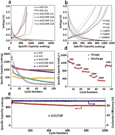
The battery performances including cycling, rate properties and long-term cycling can be observed in Fig. 3 and Fig. S3 (Supporting information). Both u-SiO and b-SiO samples delivers very high initial capacities over 3200 mAh/g, which are even higher than the n-SiO/CNF and u-SiO/CNF samples. However, their capacities sharply declines after the 1st cycle, and only maintains the capacities lower than 250 mAh/g after 100 cycles. By contrast, the n-SiO/CNF and u-SiO/CNF samples present relatively low initial capacities of 1700 mAh/g, and meanwhile show better cycling performance than both u-SiO and b-SiO. They can maintain the capacities over 1000 mAh/g after 100 cycles at a current density of 500 mA/g, which is mainly due to the reconstructed heterostructure and high elasticity cobweb-like electrode design. As shown in Fig. S4 (Supporting information), the Coulombic efficiency of n-SiO/CNF electrode appears the highest among these samples with an initial coulombic efficiency over 85%, and maintains at 98% on average, revealing that this electrode design can significantly increase the initial charge-discharge properties. It should be pointed out that the "surface effect" allows nano-scale silicon monoxide to have a wider specific surface area, thus having more reactive sites with lithium ions. However, due to the "small size effect" of nanomaterials, the contact between silicon monoxide particles and lithium ions will be more abundant in the subsequent cycling process, which can lead to a faster decay of battery capacity owing to high expansion.

|
Download:
|
| Fig. 3. (a) Charge-discharge profiles of the selected cycles for the u-SiO, b-SiO, n-SiO/CNF, and u-SiO/CNF samples at a current density of 500 mA/g. (b) Charge-discharge profiles of n-SiO/CNF anode at the current density of 2000mA/g. (c) Cycling performance for u-SiO, b-SiO, n-SiO/CNF, and u-SiO/CNF at the current density of 500 mAh/g. (d) Rate performance and (e) long-term cycling at the current density of 1000 mAh/g for n-SiO/CNF anode. | |
As displayed in the Fig. 3d, the n-SiO/CNF sample delivers the capacities of 1100, 1000, 800, 550, 400 mAh/g at the current densities of 500, 1000, 2000, 3000, 5000 mA/g, respectively, revealing excellent rate performance. Additionally, the n-SiO/CNF sample also exhibits long-term charge-discharge cycling. It can maintain the capacity at about 1000 and 780 mAh/g respectively at a high current density of 1000 and 2000 mA/g after 1000 cycles, as shown in Figs. 3b and e.
The cyclic voltammetry (CV) curves of n-SiO/CNF anode at the 1st, 2nd, 3rd, 4th and 5th cycles are shown in Fig. S5a (Supporting information). The peak of SEI-film formation at the first cycle can be clearly seen, and from the second cycle on, the cycle curves appear highly overlapped, indicating that the SEI film can be rapidly formed on the electrode surface and maintain excellent stability in the subsequent cycles due to the effective function of cobweb-like electrode design and electrolyte additives. Figs. S5b and S6 (Supporting information) reveal that the additive organic vinylene carbonate (VC) is priority to be oxidized to form a film on the electrode surface, thus stabilizing the electrode [32, 33]. Meanwhile in the EIS curves shown in Figs. S5c and d (Supporting information), the sample of n-SiO/CNF shows the typical impedance characteristics. The impedance of n-SiO/CNF electrode after 100 cycles is only 149.1 Ω, while those of u-SiO, b-SiO and u-SiO/CNF samples are 863.8, 343.6 and 223.2 Ω, respectively. This is mainly because the nanoparticles can provide more contacting area, making the electrochemical reaction in the electrode system more sufficient. Moreover, the high elastic structure can effectively accommodate the expansion effect during the battery charging and discharging processes, and the effective carbon source can significantly improve the electrode conductivity, which can all significantly reduce the impedance value.
In order to understand the excellent electrochemical performance, the enhancement mechanism of n-SiO/CNF electrode was also investigated, as shown as Fig. 4. According to the "reconstructed heterostructure" model, amorphous SiO2 phase can appear on the outside surface of SiO and amorphous Si phase can appear on the inside surface of SiO. Due to the presence of SiO2 phase in the outer layer, lithium oxide and lithium silicate compounds are firstly formed during the initial lithium insertion process, which can be expressed as Reactions 1 and 2 [8-10, 32, 33]:
|
(1) |

|
(2) |

|
Download:
|
| Fig. 4. Mechanism of the reconstructed heterostructure and high elastic cobweb-like electrode design of n-SiO/CNF nanofiber for high-efficient lithium storage. | |
Afterwards, the lithium ions reach the SiO boundary layer, and continue to generate lithium oxide and part of the lithium silicon alloy, as expressed by Reactions 3 and 4 [11, 12]:
|
(3) |

|
(4) |
Finally, when the lithium ions are embedded in the silicon boundary layer, a series of lithium silicon alloys will be generated through Reaction 5 [34-36]:

|
(5) |
Because the generated irreversible lithium oxide and lithium silicate compounds can attach on the electrode surface, the "expansion effect" can be partially relieved during the process of lithium intercalation and de-intercalation. However, in terms of micron-level SiO, part of the lithium ions cannot reach to Si layer, therefore, they will be consumed in the irreversible process, leading to the lower coulombic efficiency.
In our research, owing to the nanometer-level SiO by ball-milling, the lithium ions can directly and effectively contact with silicon layer to generate lithium-silicon alloy, thus avoiding a large amount of irreversible lithium oxide and lithium silicate generated so as to show excellent coulombic efficiency [17].
From the point of view of inhibiting expansion effect, the lithium oxide and lithium silicate compounds just mentioned above can be regarded as the first level buffer barrier. In addition, in the designed n-SiO/CNF electrode, the microscopic carbon layer formed by stirring SiO and PAN covering the individual particles and the cobweb-like carbon nanofibers constructed by electrostatic spinning can act as the second and third level buffer barriers simultaneously, which can greatly alleviate the expansion effect during the charging and discharging processes. Meanwhile, by wrapping SiO in the high elastic carbon nanofibers prepared by the electrostatic spinning, the conductivity of the electrode can be significantly increased. Moreover, by adding electrolyte additives, a thin and dense film is easy to form on the electrode surface, which plays a role of protecting the electrode, thus also effectively improves the coulombic efficiency [27, 28, 40].
In summary, a highly elastic cobweb-like electrode was successfully designed and fabricated for high-efficient lithium storage in this work through an electrostatic spinning technology. The reconstructed heterostructure of n-SiO/CNF can significantly increase the conductivity and inhibit the "expansion effect" of the silicon-based materials. Through this design and fabrication, the n-SiO/CNF electrode delivers an initial capacity of 1700 mAh/g, and maintains the capacity over 1000 mAh/g after 100 cycles at a current density of 500 mA/g. Meanwhile, this electrode delivers the capacities of 1100, 1000, 800, 550, 400 mAh/g at current densities of 500, 1000, 2000, 3000, 5000 mA/g, respectively. Furthermore, this electrode exhibits an efficient long-term electrochemical performance, maintaining the capacity at about 1000 mAh/g at a high current density of 1000mA/g after 1000 cycles. This research would provide a basis for the industrial application of silicon-based composite materials in lithium-ion batteries.
Declaration of competing interestThe authors report no declarations of interest.
AcknowledgmentsThis work was financially supported by the National Natural Science Foundation of China (Nos. 21706055, 21978073 and U1903217). The authors would also like to thank the Analytical and Testing Center of Hubei University for providing the facilities to fulfill the experimental measurements. The technical supports from Hubei Nuobang Chemical Company Co., Ltd. are also gratefully acknowledged.
Appendix A. Supplementary dataSupplementary material related to this article can be found, in the online version, at doi:https://doi.org/10.1016/j.cclet.2021.02.051.
| [1] |
F. Wu, J. Maier, Y. Yu, Chem. Soc. Rev. 49 (2020) 1569-1614. DOI:10.1039/c7cs00863e |
| [2] |
G. Liang, Z. Wu, C. Didier, et al., Angew. Chem. Int. Ed. 59 (2020) 10594-10602. DOI:10.1002/anie.202001454 |
| [3] |
D. Larcher, J.M. Tarascon, Nat. Chem. 7 (2015) 19-29. DOI:10.1038/nchem.2085 |
| [4] |
J.B. Goodenough, Y. Kim, J. Power Sources 196 (2011) 6688-6694. DOI:10.1016/j.jpowsour.2010.11.074 |
| [5] |
V. Etacheri, R. Marom, R. Elazari, G. Salitraa, D. Aurbach, Energ. Environ. Sci. 4 (2011) 3243-3262. DOI:10.1039/c1ee01598b |
| [6] |
R. Raccichini, A. Varzi, S. Passerini, B. Scrosati, Nat. Mater. 14 (2015) 271-279. DOI:10.1038/nmat4170 |
| [7] |
Z. Zhu, H.B. Zuo, S. Li, et al., J. Mater. Chem. A 7 (2019) 7533-7540. DOI:10.1039/c8ta12412d |
| [8] |
S. Choi, T.W. Kwon, A. Coskun, J.W. Choi, Science 357 (2017) 279-283. DOI:10.1126/science.aal4373 |
| [9] |
W. Chen, R.V. Salvatierra, M. Ren, J. Chen, M.G. Stanford, Adv. Mater. 32 (2020) 2002850. DOI:10.1002/adma.202002850 |
| [10] |
R. Xu, G. Wang, T. Zhou, et al., Nano Energy 39 (2017) 253-261. DOI:10.1016/j.nanoen.2017.07.007 |
| [11] |
L. Tong, P. Wang, A. Chen, et al., Carbon 153 (2019) 592-601. DOI:10.1016/j.carbon.2019.07.067 |
| [12] |
Q. Wei, Y.M. Chen, X.J. Hong, Appl. Surf. Sci. 511 (2020) 145609. DOI:10.1016/j.apsusc.2020.145609 |
| [13] |
V. Aravindan, Y.S. Lee, S. Madhavi, Adv. Energy Mater. 5 (2015) 1402225. DOI:10.1002/aenm.201402225 |
| [14] |
W.J. Yu, C. Liu, P.X. Hou, L. Zhang, X.Y. Shan, et al., ACS Nano 9 (2015) 5063-5071. DOI:10.1021/acsnano.5b00157 |
| [15] |
N. Kim, S. Chae, J. Ma, M. Ko, J. Cho, Nat. Commun. 8 (2017) 812-821. DOI:10.1038/s41467-017-00973-y |
| [16] |
X. Zuo, J. Zhu, P.M. Buschbaum, Y.J. Cheng, Nano Energy 31 (2017) 113-143. DOI:10.1016/j.nanoen.2016.11.013 |
| [17] |
C. Du, C. Gao, G. Yin, M. Chen, L. Wang, Energy Environ. Sci. 4 (2011) 1037-1042. DOI:10.1039/c0ee00428f |
| [18] |
D. Chen, W. Liao, Y. Yang, J. Zhao, J. Power Sources 315 (2016) 236-241. DOI:10.1016/j.jpowsour.2016.03.051 |
| [19] |
X. Bai, Y. Yu, H. Kung, B. Wang, J. Jiang, J. Power Sources 306 (2016) 42-48. DOI:10.1016/j.jpowsour.2015.11.102 |
| [20] |
W. Guo, X. Yan, F. Hou, et al., Carbon 152 (2019) 888-897. DOI:10.1016/j.carbon.2019.06.088 |
| [21] |
B. Lee, T. Liu, S.K. Kim, et al., Carbon 119 (2017) 438-445. DOI:10.1016/j.carbon.2017.04.065 |
| [22] |
H.W. Yang, H.Y. Park, H.G. Lee, W.S. Kang, S.J. Kim, ACS Omega 2 (2017) 3518-3526. DOI:10.1021/acsomega.7b00547 |
| [23] |
H.W. Yang, D.I. Lee, N. Kang, et al., J. Power Sources 400 (2018) 613-620. DOI:10.1016/j.jpowsour.2018.08.065 |
| [24] |
J. Liu, Q. Zhang, T. Zhang, et al., Adv. Funct. Mater. 25 (2015) 3599-3605. DOI:10.1002/adfm.201500589 |
| [25] |
Y. Yang, Y.H. Chen, J. Huang, et al., Small 14 (2018) 1801189. DOI:10.1002/smll.201801189 |
| [26] |
R.N. Guo, S.L. Zhang, H.J. Ying, et al., ACS Appl. Mater. Inter. 11 (2019) 14051. DOI:10.1021/acsami.8b21936 |
| [27] |
K. Feng, M. Li, W.W. Liu, et al., Small 14 (2018) 1702737. DOI:10.1002/smll.201702737 |
| [28] |
S. Chae, S.H. Choi, N. Kim, J. Sung, J. Cho, Angew. Chem. Int. Ed. 59 (2020) 110-135. DOI:10.1002/anie.201902085 |
| [29] |
X.W. Zhang, P.K. Patil, C. Wang, D.L. Cock, J. Power Sources 125 (2004) 206-213. DOI:10.1016/j.jpowsour.2003.07.019 |
| [30] |
H. Jung, M. Park, S.H. Han, H. Lim, S.K. Joo, Solid State Commun. 125 (2003) 206-223. |
| [31] |
L.F. Cui, Y. Yang, C.M. Hsu, Y. Cui, Nano Lett. 48 (2009) 3370-3374. DOI:10.1021/nl901670t |
| [32] |
Q. Xu, J.K. Sun, Y.X. Yin, Y.G. Guo, Adv. Funct. Mater. 28 (2017) 1705235. |
| [33] |
Q. Xu, J.K. Sun, Z.L. Yu, et al., Adv. Mater. 30 (2018) 1707430. DOI:10.1002/adma.201707430 |
| [34] |
G. Li, L.B. Huang, M.Y. Yan, et al., Nano Energy 74 (2020) 104890. DOI:10.1016/j.nanoen.2020.104890 |
| [35] |
T. Ma, H. Xu, X. Yu, et al., ACS Nano 13 (2019) 2274-2280. |
| [36] |
Z. Liu, Y. Zhao, R. He, et al., Energy Stor. Mater. 19 (2019) 299-305. DOI:10.1016/j.ensm.2018.10.011 |
| [37] |
R. Teki, M.K. Datta, R. Krishnan, et al., Small 5 (2009) 2236-2242. DOI:10.1002/smll.200900382 |
| [38] |
Q.Y. Zhang, C.F. Zhang, W.W. Luo, et al., Adv. Sci. 7 (2020) 2000749. DOI:10.1002/advs.202000749 |
| [39] |
Y.F. Wen, H.W. Zhang, ChemSusChem 13 (2020) 3887-3892. DOI:10.1002/cssc.202000911 |
| [40] |
T. Wang, X.T. Guo, H.Y. Duan, C.Y. Chen, H. Pang, Chin. Chem. Lett. 31 (2020) 654-666. DOI:10.1016/j.cclet.2019.06.002 |