 2021, Vol. 32


In the past decades, forward osmosis (FO) has attracted widespread attention as an emerging technology with applications for wastewater disposal [1, 2], pharmaceuticals industry, and so on [3]. Compared with pressure-driven reverse osmosis, nanofiltration, and ultrafiltration technologies, FO does not require additional applied pressure and relies solely on the osmotic pressure difference between the feed and draw solutions to achieve the selective separation of water, thereby having the merits of low energy consumption, simple operation, and low membrane fouling propensity [4, 5]. To date, the development of FO is still mainly limited by the need for a high-performance membrane with efficient separation properties.
A typical asymmetric forward osmosis membrane is a thin film composite membrane (TFC) comprising two layers: a dense active layer and a porous support layer fabricated by non-solvent induced phase separation [6]. The former contributes to the membrane selectivity while the latter provides channels for water transport and mechanical support. The internal concentration polarization (ICP) in the support layer generates the dominating resistance to the mass transfer in FO membrane [7]. Generally, the dilutive and concentrative ICP occurs when the active layer (AL) contacts with the feed solution (AL-FS mode) and draw solution (AL-DS mode), respectively. The ICP cannot be mitigated by simply optimizing hydrodynamic conditions [8]. Therefore, it is crucial to fabricate high-performance FO membranes to alleviate the effects of ICP [9].
In recent years, the main development of TFC membranes is focused on nanomaterial additives of the support layer to mitigate ICP as their performance can be mediated by the size, type, and amount of nanofillers [10-21]. Various inorganic nanomaterials have been widely used as additives to the polymer support layer, such as three-dimensional (3D) metal-organic framework [10-12], 2D layered double hydroxide [13, 14] or graphene oxide (GO) [15-17], 1D TiO2 nanowires [18, 19] or carbon nanotubes (CNTs) [20, 21], and 0D Ag clusters [22]. The nanofiller-mediated strategy can improve porosity and permeability of TFC membrane, and enhance the transport channels of the support layer. Park et al. found that incorporating 0.25 wt% GO in the support layer significantly improved water permeability [23]. Similarly, embedding CNTs in the support layer can mitigate ICP, thereby increasing the transport flux of water molecules due to the smooth graphitic walls and nanoscale channels of CNTs [24-26]. Hence, the addition of carbon-based nanomaterials in the support layer can provide efficient water transport due to increased water channels in TFC membranes.
Carbon dots (CDs) have been potentially applied in separation membrane as a zero-dimensional nanostructured filler due to its simple production process, excellent stability, small size, and rich functional groups [27-31]. Jafari et al. prepared polyvinylidenefluride (PVDF) nanofibrous membranes modified with CDs for air-gap membrane distillation, which exhibited a larger porosity and enhanced performance [32]. Sun et al. introduced the functionalized GQDs to the polyamide layer and found that the presence of SO42− can induce the better nanofiltration performance [33]. Although the introduction of GQDs in the polyamide (PA) layer can change the properties of membrane surface or improve the permeability without the need for cross-flow filtration, the channels and formation mechanism within the polymer support membrane are rarely mentioned.
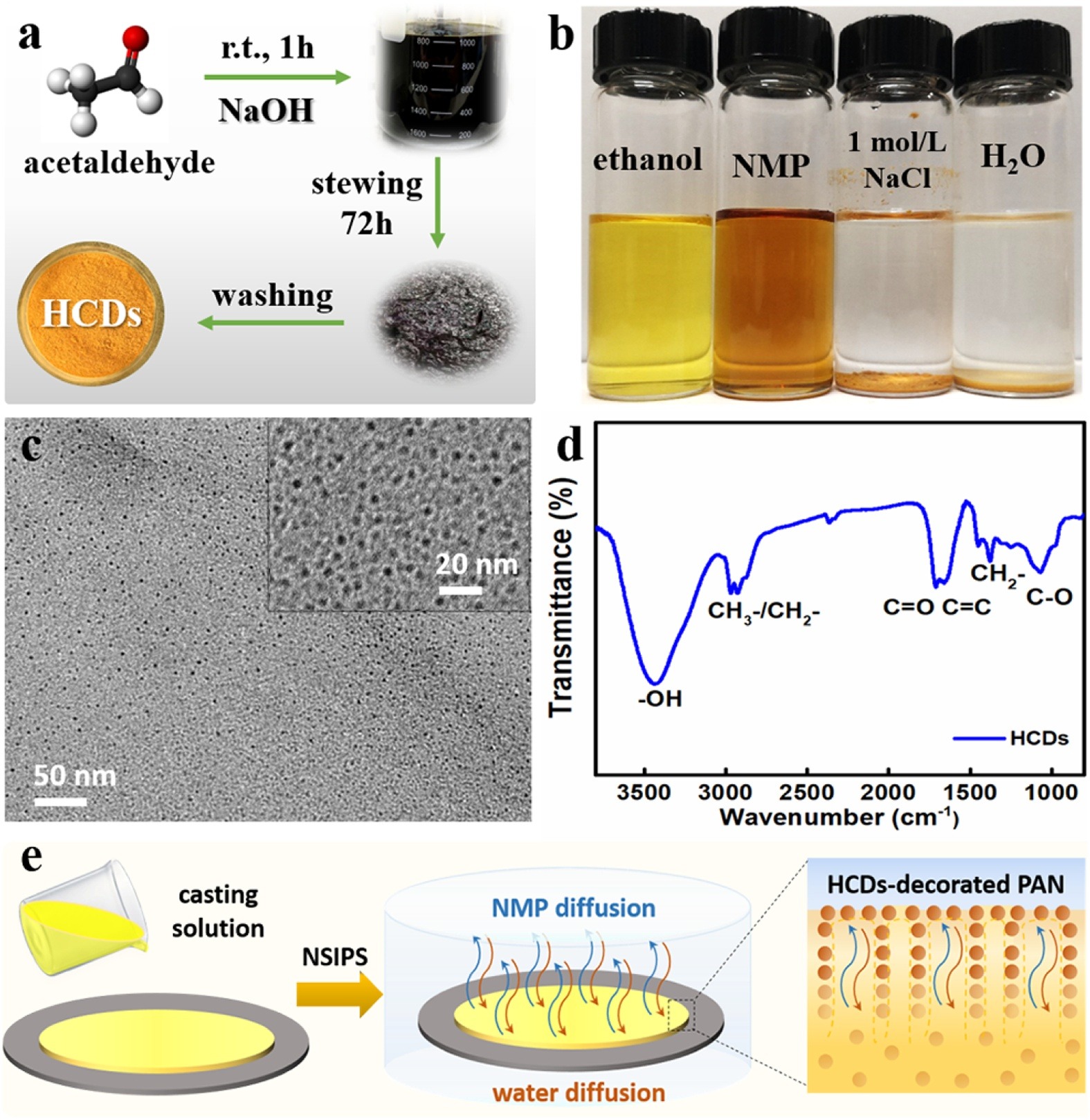
Herein, hydrophobic carbon dots (HCDs) are used to regulate water channels for an efficient FO membrane. A new TFC membrane is fabricated by introducing HCDs as the nanofiller into the polyacrylonitrile (PAN) support layer. Hydrophobic carbon dots were facilely prepared through mixing acetaldehyde aqueous solution and sodium hydroxide at room temperature (Fig. 1a) [34]. The yellow HCDs can be evenly dispersed in organic solvents, such as ethanol and 1-methyl-2-pyrrolidinone, but not in water and 1 mol/L NaCl solution (Fig. 1b), which verifies the hydrophobicity of the resulting HCDs and good dispersion in organic solutions. It has uniform diameter in the range of 3.0~5.0 nm (Fig. 1c). The FTIR spectrum shows their diverse functional groups (Fig. 1d) including the stretching vibrations of C-OH (~3436 cm−1), C=O (1710 cm−1), and C=C (1660 cm−1). In Fig. 1e, the homogeneous PAN/1-methyl-2-pyrrolidone (NMP) solution containing HCDs was first casted on glass and was then precipitated by non-solvent induced phase separation to form HCD-decorated PAN support layers.

|
Download:
|
| Fig. 1. (a) Facile preparation procedure, (b) solubility in different solvents, (c) high-resolution TEM images, and (d) FTIR spectrum of HCDs, and (e) the schematic diagram on the HCDs-decorated PAN membrane. | |
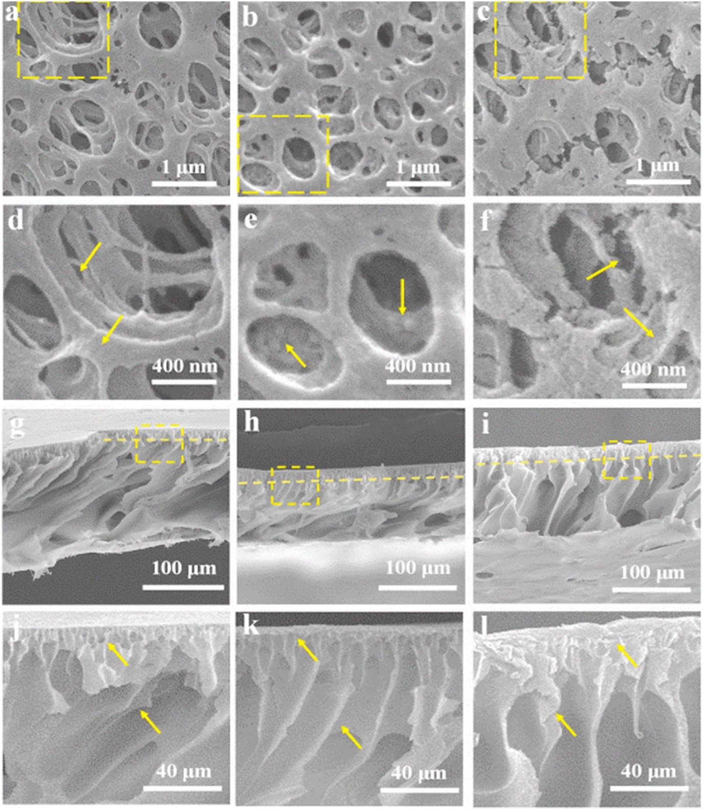
Fig. 2 shows the morphologies of the PAN support layer before and after introducing 10 wt% HCDs. For the pristine membrane (S-0), a porous structure can be clearly observed on the top surface (Fig. 2a). The enlarged figure (Fig. 2d) shows the smooth wall of the hierarchical pores. The HCDs decorated PAN membrane (hereafter, S-0.1) exhibited a more homogeneous pore distribution and more apertures with a decreased mean pore diameter (Fig. 2b). In contrast, the membrane surface is rougher with micro-convex structures formed on the pore wall (Fig. 2e). When tiny HCDs were dispersed in the PAN/NMP solution, the driving force of the bidirectional diffusion process between water and NMP is mediated, thereby changing the phase separation process [35]. Due to the excellent miscibility with ethanol, HCDs can be removed from S-0.1 membrane to clarify their role in the PAN support layer.Fig. 2c shows the rougher surface and interior skeleton of the S−OH membrane with the formation of tiny voids, verifying the HCDs can mediate effectively the skeleton structure of support layer.

|
Download:
|
| Fig. 2. SEM images for the top surface and the corresponding cross-section of PAN support layers. (a, d, g, j) S-0, (b, e, h, k) S-0.1, (c, f, i, l) S−OH. | |
Figs. 2g–l shown the cross-section morphologies of PAN support layers before and after introducing HCDs, which exhibit an asymmetric structure including a smooth top surface of approximately 15 μm and a porous sub-layer [36, 37]. S-0 support layer has a scrambled pore structure and interpenetrating interior macro-pores, while S-0.1 support layer (Fig. 2k) has even interior pore passages and an ordered pore wall. The tiny pore passages in the cortical layer are interpenetrated well with the interior macropores, thereby forming finger-like structure with hierarchical channels for water transport [37]. When HCDs was removed from the support layer with ethanol, Fig. 2f shows the similar surface properties between S-0 and S−OH membranes, but the latter presents the larger finger-shaped pore structure, indicating the skeleton regulation role of HCDs in the PAN support layer. Moreover, it can effectively induce the formation of the internal micro-convex structure.
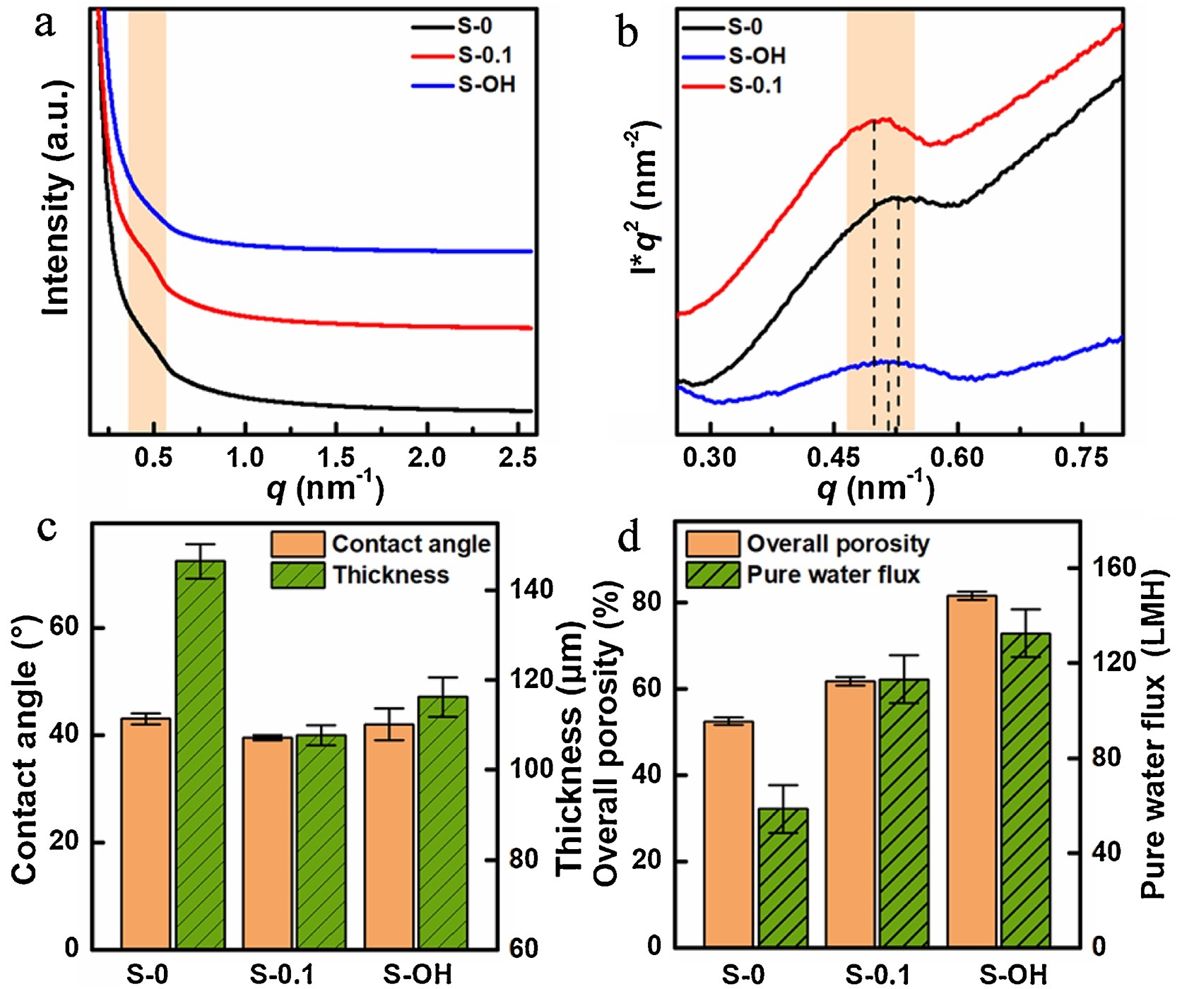
Based on the fluorescence mapping of HCDs [38], S-0.1 membrane shows the even distribution of HCDs in the PAN support layer under excitation wavelengths of 350, 477, and 530 nm (Fig. S1 in Supporting information). In contrast, both S-0 and S−OH membranes have no fluorescence behavior of CQDs. Fig. S2 (Supporting information) shows the significant peaks at 2248 (CN), 1378 (−CH2), 3436 (C−OH) and 1710 cm−1 (C=O) [39], respectively. The characteristic peaks of S-0.1 support layer confirm the successful introduction of HCDs into the support layer.Fig. 3a displays strong "zero angle scattering" of small angle X-ray diffraction (SAXS) for three support layers, which indicates the presence of micro-voids, grain boundary phase, and isolated amorphous regions [40, 41]. However, compared to S-0 membrane, a conspicuous shoulder peak can be observed at scattering vector magnitude q of 0.5 nm−1 for S-0.1 membrane, which illustrates the presence of HCDs or the changes in the internal structure of support layer. The SAXS profile of S−OH membrane is similar with that of S-0 membrane, indicating that HCDs fill the internal pore paths in the S-0.1 membrane. In each case, the SAXS curves are asymmetrical, reflecting the presence of lamellar stacks with different spacing values. Fig. 3b shows the peak of Lorentz correction curves shift to higher q values. The peak positions at qmax are 0.525, 0.499, and 0.509 nm−1 for the scattering curves at S-0, S-0.1, and S−OH, with a long period value of 11.96, 12.60, and 12.34 nm, respectively. This phenomenon reflects that the heteronuclearity of HCDs increases the crystal nuclei and bulk micro-convex structure of PAN support layers.

|
Download:
|
| Fig. 3. (a) Intensity-q curves, (b) the fitted I × q2 vs. q plots of three support layers, (c) Contact angle and thickness, and (d) Overall porosity and Pure water flux of three PAN support membranes. | |
Fig. 3c shows a comparison of contact angle and thickness for the fabricated support layers. S-0.1 membrane has a slightly lower water contact angle value than S-0 membrane, indicating that the introduction of HCDs slightly increases hydrophilicity. The increase of the contact angle value for S−OH membrane may be caused by the rough surface after removing the HCDs (Fig. 2c). Furthermore, the membrane thickness decreases from 146 μm of S-0 to 107 μm of S-0.1 after adding HCDs, but it becomes larger for the S−OH membrane washed with ethanol. The HCDs could behave like a polymer additive to improve the gelatinous precipitation rate of membrane [42]. In addition, the porosity of the PAN support membrane (Fig. 3d) increases from 52.56% to 61.79%, thereby mainly resulting from the change of its phase separation behavior. After removing HCDs, the porosity of the S−OH membrane increases to 81.58%, indicating the effective filling of HCDs in the S-0.1 PAN membrane matrix. Correspondingly, the pure water flux increases from 58.49 LMH bar−1 to 113.21 LMH bar−1 due to the introduction of HCDs, and further increases to 132.70 LMH bar−1 when HCDs are removed.
Fig. S3 (Supporting information) shows all surfaces of the polyamide layers exhibit typical "ridge-valley" morphology [43-45]. The surface of TFC-0.1 membrane has a higher flatness than other three TFC membranes, indicating that introducing HCDs into the support layer benefits for the formation of integrated PA layer. Some tiny protuberances are evenly distributed on the surface of TFC-0 membrane. For comparison, when the HCDs were eluted from S-0.1 support layer, as shown in Fig. 3c, the formed PA layer of the resulting OH-TFC membrane exhibits obvious wrinkled branches, which could result from the uneven surface of PAN support layer. However, when the HCDs of TFC-0.1 membrane were eluted with ethanol, some large leaf-like structures are found on the surface of TFC-0.1-OH (Fig. S3d), indicating the PA layer is easily swelled by ethanol. Figs. S4a and b (Supporting information) shows that the PA layer of TFC-0.1 membrane exhibits a relatively thin surface approximately 230 nm thick, while TFC-0 is approximately 270 nm thick. Compared to the surface of S-0 support layer, the more uniform surface pores and internal channels of HCDs-decorated S-0.1 membrane may facilitate the adhesion of MPD monomers on the surface, subsequently leading to the formation of thin and dense PA layer. Figs. S4c and d (Supporting information) shows the average roughness Ra is 51.4 nm for TFC-0.1 membrane, while it is about 42.8 nm for TFC-0 membrane. The relatively higher surface roughness of TFC-0.1 membrane could result from the nano-scale HCDs aggregates on the surface of S-0.1 support layer.
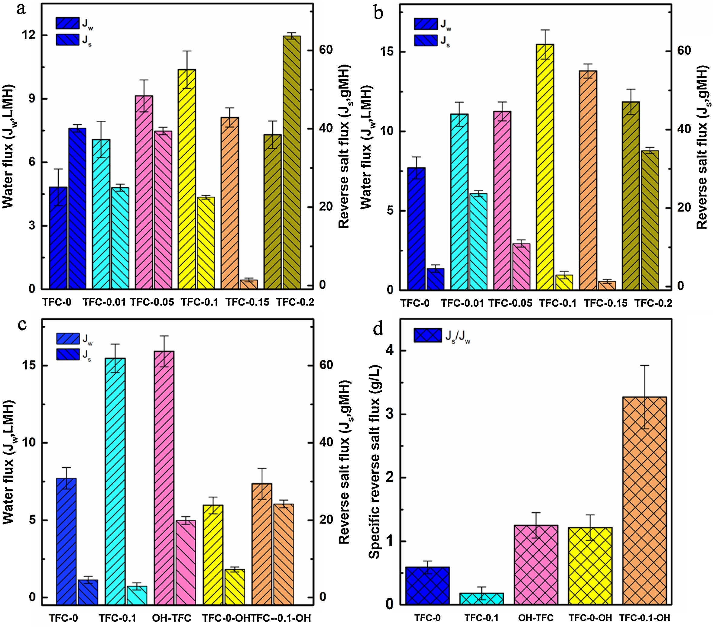
The forward osmosis performance of TFC membranes was evaluated with AL-FS and AL-DS modes, where deionized water was used as the feed solution and 1 mol/L NaCl was used as draw solution [46, 47]. Regardless of the AL-FS mode or AL-DS mode, the TFC membrane with HCDs has higher water flux than unmodified TFC-0. In addition, the water flux tends to increase and the reverse salt flux tends to decrease as increasing the amount of added HCDs to 10 wt% of PAN polymer. The water flux of TFC-0.1 increased to 15.47 L m−2h−1 compared to the 7.71 L m−2h−1 of TFC-0, whereas the reverse salt flux of TFC-0.1 decreased to 2.90 g m−2h−1 compared to the 4.56 g m−2h−1 of TFC-0. The HCDs content of 20% results in a 23% decrease in the water flux, which could be attributed to the accumulation of HCD and the severe ICP impact in TFC membrane.
In addition, when the HCDs in S-0.1 support layer were eluted with ethanol before preparing PA layer (Figs. 4c and d), the water flux of the obtained OH-TFC membrane was slightly enhanced but the reverse salt flux also increased, thus resulting in the Js/Jw value increased from 0.18 g/L for TFC-0.1 to 3.27 g/L for TFC-0.1-OH, which means the removal of HCDs from PAN support layer will deteriorate the permselectivity of TFC membrane. As a control, the PA layer was prepared after the S-0 support layer without HCDs was washed with ethanol. The obtained TFC-0-OH membrane has similar water flux, reverse salt flux, and Js/Jw values with TFC-0 membrane, indicating the ethanol washing does not destroy the skeleton of PAN support layer. However, when HCDs in TFC-0.1 membrane are eluted with ethanol, the water flux of TFC-0.1-OH is close to TFC-0, but the specific reverse salt flux (Js/Jw) is evidently worse than TFC-0 and TFC-0.1 membranes due to the swelling of PA layer in ethanol. These results indicate that water flux positively correlates with the overall porosity of support layer while the reverse salt flux correlates with the surface integrity of the PA layer.

|
Download:
|
| Fig. 4. Water flux and reverse salt flux values of different TFC-FO membranes. (a) FO test under AL-FS mode and (b) AL-DS mode of TFC-FO membranes with the different percentages of HCDs in PAN support layers. (c) Water flux (Jw) and reverse salt flux (Js). (d) Specific reverse salt flux values (Js/Jw). Test conditions: feed solution: DI water, draw solution: 1 mol/L NaCl, peristaltic pump speed: 100 rpm, temperature: 25 ℃. | |
The intrinsic separation properties of the TFC membranes were shown in Table S1 (Supporting information). The A value of the HCDs-modified TFC-0.1 membrane significantly increased to 2.26±0.24 LMH bar−1 from the 1.32±0.18 LMH bar−1 of the unmodified TFC-0 membrane. Moreover, the NaCl rejection (Rs) increased to 94.4%, and the structural parameters (S) decreased to 1.88 × 10⁻⁴ m. This result reveals that the HCDs-decorated support layer can alleviate the ICP effect of TFC membranes and benefit for water permeability [20]. The increased water permeability in TFC-0.1 membrane could be attributed to the formation of coherent finger-like hierarchical channels and the increasing porosity in support layer. The lower S value may result from the high porosity and connectivity of TFC-0.1 after adding HCDs [48]. When HCDs in S-0.1 support layer were eluted, the water permeability in obtained OH-TFC membrane slightly decreased but the salt permeability increased compared to TFC-0.1 membrane. Although HCDs removal is beneficial for increasing the porosity and decreasing the structural parameter of OH-TFC, the formed PA layer is uneven or non-integrated, thereby adverse for the NaCl rejection rate. In addition, when TFC-0.1 membrane was washed with ethanol, the water permeability in TFC-0.1-OH membrane further decreased and the salt permeability evidently increased. The minimum specific reverse salt flux Js/Jw of 0.18 g/L at AL-DS mode was achieved for TFC-0.1 membrane, which is significantly lower than those previously reported in literatures as listed in Table S2.
In conclusion, tiny HCDs with abundant functional groups were found to have good compatibility with PAN. After introducing HCDs, the PAN membrane exhibited a more homogenous pore distribution and smaller aperture. The HCDs in the membrane matrix can induce the formation of the PAN membrane with coherent finger-like hierarchical channels and micro-convex structure on the pore wall, thereby increasing the hydrophilicity, porosity, and pure water flux. Compared to original membrane, TFC–FO membrane with 10 wt% HCDs showed high water flux (15.47 L m−2h−1) and low reverse salt flux (2.9 g m−2h−1) with 1 mol/L NaCl as the draw solution. Therefore, HCDs can be utilized as an effective channel designer to boost FO performance.
Declaration of competing interestThe authors report no declarations of interest.
AcknowledgmentsThis work was financially supported by the National Key Research and Development Project (No. 2019YFC1907801), the Hunan Provincial Science and Technology Plan Projects (No. 2019JJ30031), and the Innovation-Driven Project of Central South University (No. 2020CX007).
Appendix A. Supplementary dataSupplementarymaterial related to this article can befound, in the online version, at doi:https://doi.org/10.1016/j.cclet.2021.03.028.
| [1] |
S. Zhao, L. Zou, C.Y. Tang, D. Mulcahy, J. Mem. Sci. 396 (2012) 1-21. DOI:10.1016/j.memsci.2011.12.023 |
| [2] |
J. Wang, D.S. Dlamini, A.K. Mishra, et al., J. Mem. Sci. 454 (2014) 516-537. DOI:10.1016/j.memsci.2013.12.034 |
| [3] |
M. Xie, L.D. Nghiem, W.E. Price, M. Elimelech, Envi. Sci. & Tech. 1 (2014) 191-195. |
| [4] |
L. Xu, J. Xu, B. Shan, X. Wang, C. Gao, J. Mater. Chem. A 5 (2017) 7920-7932. DOI:10.1039/C7TA00492C |
| [5] |
S. Xiong, J. Zuo, Y.G. Ma, et al., J. Mem. Sci. 520 (2016) 400-414. DOI:10.1016/j.memsci.2016.07.034 |
| [6] |
X. Zhang, J. Tian, Z. Ren, et al., J. Mem. Sci. 520 (2016) 529-539. DOI:10.1016/j.memsci.2016.08.005 |
| [7] |
H.L. Zuo, G.P. Cao, M. Wang, et al., Desalination 421 (2017) 12-22. DOI:10.1016/j.desal.2017.04.021 |
| [8] |
P. Lu, S. Liang, L. Qiu, et al., J. Mem. Sci. 504 (2016) 196-205. DOI:10.1016/j.memsci.2015.12.066 |
| [9] |
T.S. Chung, S. Zhang, K.Y. Wang, J. Su, M.M. Ling, Desalination 287 (2012) 78-81. DOI:10.1016/j.desal.2010.12.019 |
| [10] |
J.Y. Lee, Q. She, F. Huo, C.Y. Tang, J. Mem. Sci. 492 (2015) 392-399. DOI:10.1016/j.memsci.2015.06.003 |
| [11] |
M. Arjmandi, M. Peyravi, M.P. Chenar, M. Jahanshahi, J. Mem. Sci. 579 (2019) 253-265. DOI:10.1016/j.memsci.2019.02.020 |
| [12] |
N. Ma, J. Wei, S. Qi, et al., J. Mem. Sci. 441 (2013) 54-62. DOI:10.1016/j.memsci.2013.04.004 |
| [13] |
P.M. Pardeshi, A.K. Mungray, A.A. Mungray, Desalination 421 (2017) 149-159. DOI:10.1016/j.desal.2017.01.041 |
| [14] |
P. Lu, S. Liang, T. Zhou, et al., RSC Adv. 6 (2016) 56599-56609. DOI:10.1039/C6RA10080E |
| [15] |
H. Zhang, L. Bin, J. Pan, et al., J. Mem. Sci. 539 (2017) 128-137. DOI:10.1016/j.memsci.2017.05.075 |
| [16] |
S. Lim, M.J. Park, S. Phuntsho, et al., Polymer 110 (2017) 36-48. DOI:10.1016/j.polymer.2016.12.066 |
| [17] |
F.F. Ma, D. Zhang, T. Huang, et al., Chem. Eng. J. 358 (2019) 1065-1073. DOI:10.1016/j.cej.2018.10.121 |
| [18] |
D. Emadzadeh, W.J. Lau, T. Matsuura, et al., Chem. Eng. J. 237 (2014) 70-80. DOI:10.1016/j.cej.2013.09.081 |
| [19] |
X. Zhang, T. Zhang, D.D. Sun, Adv. Funct. Mater. 19 (2009) 3731-3736. DOI:10.1002/adfm.200901435 |
| [20] |
Y.H. Pan, Q.Y. Zhao, L. Gu, Q.Y. Wu, Desalination 421 (2017) 160-168. DOI:10.1016/j.desal.2017.04.019 |
| [21] |
X. Zhang, L. Shen, C.Y. Guan, et al., J. Mem. Sci. 564 (2018) 328-341. DOI:10.1016/j.memsci.2018.07.043 |
| [22] |
S.F. Pan, T.Y. Wang, Q. Liu, L.B. Zhong, Y.M. Zheng, Ind. Eng. Chem. Res. 58 (2019) 984-993. DOI:10.1021/acs.iecr.8b04893 |
| [23] |
M.J. Park, S. Phuntsho, T. He, et al., J. Mem. Sci. 493 (2015) 496-507. DOI:10.1016/j.memsci.2015.06.053 |
| [24] |
M. Amini, M. Jahanshahi, A. Rahimpour, J. Mem. Sci. 435 (2013) 233-241. DOI:10.1016/j.memsci.2013.01.041 |
| [25] |
S. Kar, R.C. Bindal, P.K. Tewari, Nano Today 7 (2012) 385-389. DOI:10.1016/j.nantod.2012.09.002 |
| [26] |
Y. Wang, R. Ou, Q. Ge, H. Wang, T. Xu, Desalination 330 (2013) 70-78. DOI:10.1016/j.desal.2013.09.028 |
| [27] |
D.L. Zhao, T.S. Chung, Water Res. 147 (2018) 43-49. DOI:10.1016/j.watres.2018.09.040 |
| [28] |
G. Fang, J. Zhou, Y. Hu, et al., J. Power Sources 275 (2015) 694-701. DOI:10.1016/j.jpowsour.2014.11.052 |
| [29] |
Y. He, D.L. Zhao, T.S. Chung, J. Mem. Sci. 564 (2018) 483-491. DOI:10.1016/j.memsci.2018.07.031 |
| [30] |
P. He, M. Yan, G. Zhang, et al., Adv. Energy Mater. 7 (2017) 1601920. DOI:10.1002/aenm.201601920 |
| [31] |
S.Y. Lu, L.Z. Sui, J.J. Liu, et al., Adv. Mater. 29 (2017) 1603443. DOI:10.1002/adma.201603443 |
| [32] |
A. Jafari, M.R.S. Kebria, A. Rahimpour, G. Bakeri, Chem. Eng. Process. 126 (2018) 222-231. DOI:10.1016/j.cep.2018.03.010 |
| [33] |
H.Z. Sun, P.Y. Wu, J. Mem. Sci. 564 (2018) 394-403. DOI:10.1016/j.memsci.2018.07.044 |
| [34] |
H.S. Hou, C.E. Banks, M.J. Jing, Y. Zhang, X.B. Ji, Adv. Mater. 27 (2015) 7861-7866. DOI:10.1002/adma.201503816 |
| [35] |
L. Shen, X. Zhang, L. Tian, et al., J. Mem. Sci. 600 (2020) 117866. DOI:10.1016/j.memsci.2020.117866 |
| [36] |
J. Peng, Y. Su, W. Chen, et al., Ind. Eng. Chem. Res. 49 (2010) 4858-4864. DOI:10.1021/ie9018963 |
| [37] |
Y. Sun, L. Xue, Y. Zhang, et al., Desalination 336 (2014) 72-79. DOI:10.1016/j.desal.2013.12.036 |
| [38] |
W.D. Li, Y. Liu, B.Y. Wang, et al., Chin. Chem. Lett. 30 (2019) 2323-2327. DOI:10.1016/j.cclet.2019.06.040 |
| [39] |
C. Zhang, K. Wei, W. Zhang, et al., ACS Appl. Mater. Interfaces 9 (2017) 11082-11094. DOI:10.1021/acsami.6b12826 |
| [40] |
M. Sharma, G. Madras, S. Bose, Macromolecules 47 (2014) 1392-1402. DOI:10.1021/ma4023718 |
| [41] |
Y. Lv, H. Zhu, M.F. An, et al., J. Polym. Sci. 34 (2016) 1510-1522. |
| [42] |
T. Malik, H. Razzaq, S. Razzaque, Polym. Bull. 76 (2019) 4879-4901. DOI:10.1007/s00289-018-2616-3 |
| [43] |
H.R. Zuo, G.P. Cao, Appl. Surf. Sci. 436 (2018) 1181-1192. DOI:10.1016/j.apsusc.2017.11.192 |
| [44] |
H.R. Zuo, G.P. Cao, Appl. Surf. Sci. 433 (2018) 945-956. DOI:10.1016/j.apsusc.2017.08.158 |
| [45] |
M. Tian, Y.N. Wang, R. Wang, Desalination 401 (2017) 142-150. DOI:10.1016/j.desal.2016.04.003 |
| [46] |
W. Gai, D.L. Zhao, T.S. Chung, J. Mem. Sci. 551 (2018) 94-102. DOI:10.1016/j.memsci.2018.01.034 |
| [47] |
P. Hajighahremanzadeh, M. Abbaszadeh, S.A. Mousavi, et al., J. Appl. Polym. Sci. 133 (2016) 44130-44139. |
| [48] |
Y. Li, L.H. Wee, J.A. Martens, J. Mem. Sci. 523 (2017) 561-566. DOI:10.1016/j.memsci.2016.09.065 |