 2021, Vol. 32


b School of Physics, Harbin Institute of Technology, Harbin 150001, China
 Qingjiang Yu received his Ph.D. degree from Jilin University in 2008. Then he joined in Changchun Institute of Applied Chemistry, Chinese Academy of Science, as a postdoctoral researcher. In 2012, he became an associate professor at Harbin Institute of Technology. He joined in TAFEL New Energy Technology Co., Ltd. in 2018. His current research interests are solid-state lithium metal batteries and new materials development for lithium-ion batteries.
;
Qingjiang Yu received his Ph.D. degree from Jilin University in 2008. Then he joined in Changchun Institute of Applied Chemistry, Chinese Academy of Science, as a postdoctoral researcher. In 2012, he became an associate professor at Harbin Institute of Technology. He joined in TAFEL New Energy Technology Co., Ltd. in 2018. His current research interests are solid-state lithium metal batteries and new materials development for lithium-ion batteries.
; |
 Kecheng Jiang received his Ph.D. degree from Institute of Chemistry, Chinese Academy of Sciences, in 2014. He joined TAFEL New Energy Technology Co., Ltd. in 2016. He is now interested in the development of new materials and related technologies for electric vehicle batteries.
;
Kecheng Jiang received his Ph.D. degree from Institute of Chemistry, Chinese Academy of Sciences, in 2014. He joined TAFEL New Energy Technology Co., Ltd. in 2016. He is now interested in the development of new materials and related technologies for electric vehicle batteries.
; |
 Cuiling Yu received his Ph.D. degree from Jilin University in 2008. Then she worked as a senior engineer at Jilin Institute of Metrology. In 2011, she joined in Harbin Institute of Technology. Her current research interests are focused on photoelectrochemical cells and lithium-ion batteries.
;
Cuiling Yu received his Ph.D. degree from Jilin University in 2008. Then she worked as a senior engineer at Jilin Institute of Metrology. In 2011, she joined in Harbin Institute of Technology. Her current research interests are focused on photoelectrochemical cells and lithium-ion batteries.
; |
 Xianjin Chen received his B.S. and M.S. from Shanxi University of Science and Technology in 2014 and 2017, respectively. Then he joined in the Fujian Institute of Research on the Structure, Chinese Academy of Sciences. In 2019, he worked as an engineer at TAFEL New Energy Technology Co., Ltd. He is now interested in solid-state lithium metal batteries.
;
Xianjin Chen received his B.S. and M.S. from Shanxi University of Science and Technology in 2014 and 2017, respectively. Then he joined in the Fujian Institute of Research on the Structure, Chinese Academy of Sciences. In 2019, he worked as an engineer at TAFEL New Energy Technology Co., Ltd. He is now interested in solid-state lithium metal batteries.
; |
 Chuanjian Zhang received his Ph.D. degree from Qingdao Institute of Bioenergy and Bioprocess Technology, Chinese Academy of Sciences, in 2013. After a 29-months stay as a material engineer in the Watt lab, Huawei Technology, he joined in TAFEL New Energy Technology Co., Ltd. in 2018. His research interests are high-energydensity lithium-ion battery anode materials, such as silicon anode and high capacity artificial graphite.
;
Chuanjian Zhang received his Ph.D. degree from Qingdao Institute of Bioenergy and Bioprocess Technology, Chinese Academy of Sciences, in 2013. After a 29-months stay as a material engineer in the Watt lab, Huawei Technology, he joined in TAFEL New Energy Technology Co., Ltd. in 2018. His research interests are high-energydensity lithium-ion battery anode materials, such as silicon anode and high capacity artificial graphite.
; |
 Yi Yao received his Ph.D. degree from Dalian Institute of Chemistry & Physics, Chinese Academy of Sciences, in 2015. He joined TAFEL New Energy Technology Co., Ltd. in 2018. He is now interested in cathode materials development for lithium-ion batteries.
;
Yi Yao received his Ph.D. degree from Dalian Institute of Chemistry & Physics, Chinese Academy of Sciences, in 2015. He joined TAFEL New Energy Technology Co., Ltd. in 2018. He is now interested in cathode materials development for lithium-ion batteries.
; |
 Bin Jiang received his B.S. and M.S. from Qingdao University of Science and Technology in 2006 and 2009, respectively. Then he joined in Amperex Technology Limited and Contemporary Amperex Technology Co., Ltd. in 2009 and 2011, respectively, studying the lithiumion battery design for electric vehicles. He and his partners established Tafel New Energy Technology Co., Ltd. in 2015. He is now interested in advanced energy materials and their applications in electric vehicle batteries.
;
Bin Jiang received his B.S. and M.S. from Qingdao University of Science and Technology in 2006 and 2009, respectively. Then he joined in Amperex Technology Limited and Contemporary Amperex Technology Co., Ltd. in 2009 and 2011, respectively, studying the lithiumion battery design for electric vehicles. He and his partners established Tafel New Energy Technology Co., Ltd. in 2015. He is now interested in advanced energy materials and their applications in electric vehicle batteries.
; |
 Huijin Long received his B.S. and Ph.D. from Jilin University in 2004 and 2009, respectively. He then joined in Changchun institute of applied chemistry Chinese academy of science as a postdoctoral researcher. In 2011, he became an engineer at Contemporary Amperex Technology Co., Ltd., in charge of improving the service life of electric vehicle batteries. He and his partners established Tafel New Energy Technology Co., Ltd. in 2015. His current research interests are focused on in the development of new materials and advanced technologies for electric vehicle batteries.
|
Since Sony launched the first commercial lithium-ion batteries (LIBs) in 1991, considerable endeavors have been devoted to improving rechargeable LIBs and to developing new materials, owing to the ever-increasing demand for high energy density and safety for portable electronics, electric vehicles, grid energy storage systems [1-3]. Over the past 30 years, the energy density of LIBs has steadily enhanced while their cost had dramatically decreased. To date, the energy density of the present high-nickel-content cathode/silicon-carbon anode system has reached a bottleneck of ~300 Wh/kg, which is not enough to solve "range anxiety" of new electric vehicles [4, 5]. To maximize energy density of state-of-the-art LIBs, Li metal is considered to be an ideal anode material due to its rather high theoretical specific capacity (3860 mAh/g) and ultralow electrochemical potential (–3.04 V vs. standard hydrogen electrode) [6-8]. However, the serious issue of Li metal anodes in conventional liquid batteries is the growth of Li dendrites, which could pierce through the separator, leading to internal short circuit or even fire/explosion [9-12].
Compared with liquid electrolytes with leakage, flammability, and irreversible decomposition issues, solid-state electrolytes (SSEs) are regarded as a promising candidate to suppress uneven electrodeposition of Li and/or hinder the formation of Li dendrites, which can enhance the safety performance of LIBs [13-19]. In general, SSEs can be divided into inorganic solid electrolytes and solid polymer electrolytes (SPEs) [2, 20, 21]. The inorganic solid electrolytes mainly include oxide-based SSEs, sulfide-based SSE and etc. [22]. Oxide-based SSEs, such as garnet-type Li7-xLa3M2-xO12 (M=Ta, Nb, Zr) [23, 24], NASICON-type phosphates [25, 26] and perovskite-type Li3xLa2/3-xTiO3 [27, 28], have been investigated extensively due to their high ionic conductivity (10−4–10−2 S/cm). However, there is high interfacial resistance between the oxide-based SSEs and electrodes. Moreover, they cannot entirely prevent the dendrite formation and growth into their grain boundaries [29, 30]. Sulfide-based SSEs have been widely reported to exhibit extremely high ionic conductivities. The room-temperature ionic conductivities of Li10GeP2S12 (1.2 × 10⁻² S/cm) and Li9.54Si1.74P1.44S11.7Cl0.3 (2.5 × 10⁻² S/cm) are comparable to or higher than those of organic liquid electrolytes currently used in the commercial lithium-ion systems [31, 32]. However, sulfide-based SSEs are very sensitive to moisture (generating toxic H2S). Furthermore, the electrochemical instability problem and the formation of space charge layers between sulfide-based SSEs and electrode materials seriously hinder the application of sulfide-based SSEs [33]. In comparison, SPEs can offer decent flexibility, shape versatility, light weight and low-cost processing. Unfortunately, the low room-temperature ionic conductivity (10−7–10−5 S/cm), narrow operating temperature, and poor mechanical property prevent SPEs from their practical use in lithium batteries. To enhance the SPE performance, several approaches such as cross-linking [34], forming block copolymers [35], adding plasticizers [36], and introducing inorganic fillers [37-43] have been widely explored. Among these attempts, incorporating inorganic fillers into SPEs to prepare composite solid polymer electrolytes (CSPEs) can effectively enhance their ionic conductivities and electrochemical stability, as well as mechanical strength.
In general, inorganic fillers can be classified into two types: inactive fillers and active fillers. Inactive fillers, such as inert ceramic fillers (Al2O3, SiO2, TiO2, ZrO2 and MgO), oxygen-ion conducting ceramic fillers, ferroelectric ceramic fillers, and clays, cannot directly offer transport pathways for Li+ in electrolytes but can facilitate Li+ transport via the amorphization of polymers and the creation of space-charge regions. Active fillers, such as Li3N, Li7-xLa3Zr2-xTaxO12, Li3−2x(Al1−xTix)2(PO4)3, Li3xLa2/3-xTiO3 and Li10GeP2S12), are fast Li-ion conductors, which can exhibit high ionic conductivities and Li+ transference numbers. Moreover, inorganic fillers with various morphologies, such as nanoparticles, nanowires, nanofibers, and three-dimensional (3D) framework, can also be used to improve the mechanical and electrochemical properties of CSPEs. Therefore, inorganic fillers are preferred for designing high-performance CSPEs. In this review, we will summarize the recent progress of CSPEs with different inorganic fillers. The influences of the category, nanostructure, size and concentration of inorganic fillers on the performance of CSPEs will be discussed in detail.
2. Composite solid polymer electrolytes with inorganic fillers 2.1. Inactive fillers 2.1.1. Inert ceramic fillersIn the past two decades, many efforts have been devoted to the investigation of the mechanism of inert ceramic fillers such as Al2O3, SiO2, TiO2, ZrO2 and MgO in enhancing the ionic conductivity of CSPEs. It has been found that these ceramic fillers incorporated into the SPEs not only play a role of solid plasticizers to prevent crystallization kinetics and to promote the retention of the amorphous phase down to sub-ambient temperatures, but also have influences on the cationic mobility. The interactions between the surface groups of the ceramic fillers and both the polymer segments and the lithium salt anions may be further explained in terms of the Lewis acid-base interactions [44]. According to this extension of the model, the Lewis acid groups of the added ceramic fillers (e.g., the -OH groups on the filler surface) may quite likely compete with the Lewis-acid lithium cations for the formation of complexes with the polymer chains, as well as with the anions of the added lithium salt [45]. Thus, the ceramic fillers have two effects on improving the conductivity of SPEs [46]: (1) the fillers as cross-linking centers for the polymer segments and for the anions can lower the recrystallization of polymer chains, which may promote the structure modifications of the polymer chains and Li+ conducting pathways at the filler surface; (2) the fillers as Lewis acid–base interaction centers with the ionic species of electrolytes can decrease ionic coupling of anions with Li+, which may facilitate the salt dissociation via a sort of "ion-ceramic complex" formation. The two effects may account for the enhancement of the Li+ conductivity of the CSPEs in a wide temperature range.
Since the discovery of the ionic conductivity of poly(ethylene oxide) (PEO) complexes with alkali metal salts [47], the PEO–LiX complex electrolytes have been extensively explored for lithium polymer batteries [48, 49]. The ethylene oxide (EO) units of PEO have a high donor number for Li+ and high chain flexibility, which are important for promoting ion transport. In addition, PEO has a high dielectric constant and strong Li+ solvating ability. However, PEO is a semi-crystalline polymer, and the amorphous phase with activated chain segments (above the glass-transition temperature, Tg) aids ion migration [50]. Unfortunately, the operation at the high temperature (above 80 ℃) for SPEs may cause the degradation of mechanical properties and limited electrochemical stability window [51, 52]. In order to suppress the adverse influences of crystallization on the ion conductivity and mechanical strength on the Li-dendrite growth, Weston and Steele reported for the first time the PEO based CSPE in 1982 [53]. The mechanical property and ionic conductivity of the (PEO)8–LiClO4 electrolyte were significantly improved by adding α-Al2O3 nanoparticles. Croce et al. [54] further demonstrated the nanometer-sized ceramic powders could perform as solid plasticizers for PEO, kinetically inhibiting crystallization on annealing from the amorphous state above 60 ℃. The obtained conductivities were around 10−4 S/cm at 50 ℃ and 10−5 S/cm at 30 ℃ in a PEO–LiClO4 electrolytes containing TiO2 and Al2O3 nanoparticles, respectively. For the PEO–LiClO4 electrolyte with TiO2 nanoparticles, the average Li+ transference number of the order of 0.6 in the 45–90 ℃ temperature range was obtained using two independent methods. The high ion conductivity and Li+ transference number at moderate temperature were the first reported convincing experimental evidence to support previous hypotheses on the role of the ceramic filler in promoting Li+ transport via a surface mechanism [55-57].
The type of the surface states of the ceramic fillers can also influence the performance of CSPEs. Croce and coworkers proposed an impressive qualitative model to explain the effect of nano-sized Al2O3 ceramic fillers with different surface groups on the conductivity of the PEO20–LiCF3SO3 system [46]. This model suggested that the enhancement in the transport properties was related to the occurrence of hydrogen bonds between the ceramic surface and both the polymer chains and the lithium salt. In this system, the conductivity enhancement in the amorphous phase, above 60 ℃, decreased in the order: Al2O3 neutral > Al2O3 acidic > Al2O3 basic > Al2O3 free while below 60 ℃ it decreases as: Al2O3 acidic > Al2O3 neutral > Al2O3 free > Al2O3 basic. Later, Jiang et al. investigated the effects of different surface modified nano-size SiO2 powders on Li+ conductivity and mechanical strength of the SPE and charge–discharge properties [58]. The addition of hydrophobic SiO2 could increase the Li+ conductivity of the SPE about one-fold. The dynamic modulus of the SPE increased 50% and 150% by adding 9.1% hydrophobic and hydrophilic SiO2, respectively. The addition of nano-size SiO2 powders enhanced greatly the interfacial stability between the SPE and lithium electrode. The capacity fading of the cell was improved by adding hydrophilic nano-sizeSiO2 powders. Moreover, the effects of the addition of nano-SiO2 and acid-modified nano-SiO2 into the PEO–LiTFSI electrolytes on the Li+ conductivity and the Li dendrite growth were studied by Liu et al. [59]. It was found that the introduction of acid-modified nano-SiO2 powders could more effectively inhibit the Li dendrite formation at the Li/PEO18LiTFSI interface, which was attributed to the enhancement of the Li+ conductivity and the suppression of the interfacial resistance between the lithium anode and the SPE. For the Li/PEO18LiTFSI/Li cell, the short circuit period caused by the Li dendrite growth of 225 h at 0.1 mA/cm2 at 60 ℃. After incorporating the acid-modified nano-SiO2 into the SPE, the short circuit period was extended to 400 h.
It was noted that the ex-situ addition of particles down to a few nanometers often resulted in the agglomeration of nanoparticles. Such agglomerations reduced the full utilization of nanoparticles with large surface areas and caused residual crystalized polymer regions. To surmount this problem, Lin et al. developed an in-situ synthesis of monodispersed SiO2 nanoparticles in the PEO–LiClO4 electrolyte [60]. This method not only provided much stronger interactions between 12-nm-diameter SiO2 nanospheres and PEO chains by chemical bonding and mechanical wrapping but also enabled better distribution of SiO2 in PEO matrix, which further enhanced the effective surface area for the Lewis acid-base interaction (Fig. 1a). With all the benefits of the well-controlled in-situ synthesis, much lower degree of crystallinity and much higher degree of LiClO4 dissociation in PEO were achieved simultaneously in the composite polymer electrolyte. As a result, the Li+ conductivity of the PEO–SiO2 CPE reached as high as 4.4 × 10⁻⁵ S/cm at 30 ℃ and 1.2 × 10⁻⁵ S/cm at 60 ℃, which was considerably enhanced compared with the ceramic filler-free PEO electrolyte and even one order of magnitude higher than its counterpart by the simple mechanical mixing (Fig. 1b). Also, the electrochemical stability window was largely extended, which could endure up to 5.5 V versus Li/Li+ without significant anodic decomposition. Additionally, the ASSLBs with the PEO–SiO2 CPE exhibited an excellent rate capability as well as good cycling performance.

|
Download:
|
| Fig. 1. (a) Schematic figures showing the procedure of in-situ hydrolysis and interaction mechanisms among PEO chains and SiO2. (b) Arrhenius plots of ionic conductivity of ceramic-free SPE, PEO-fumed SiO2 CPE, ex-situ CPE and in-situ CPE. Reproduced with permission [60]. Copyright 2016, American Chemical Society. (c) Schematic showing the synthetic procedures of the SiO2-aerogel-reinforced CSPE. (d) Arrhenius plots showing the temperature-dependent ionic conductivity of the electrolyte with and without SiO2 aerogel film as the framework. (e) Symmetric-cell cycling with a SiO2-aerogel-reinforced CSPE and an electrolyte without SiO2 aerogel. (f) Cycling stability of LFP–Li cells with and without SiO2 aerogel framework and the Coulombic efficiency of that with SiO2 aerogel at 18 ℃. Reproduced with permission [37]. Copyright 2018, Wiley-VCH. | |
In fact, there is an ionic conductivity versus elastic modulus dilemma in SPEs. High ionic conductivity generally requires low crystallinity and more mobile polymer chains, resulting in mechanically softer polymers. To overcome this dilemma, Lin et al. designed a new class of CSPE composed of an interconnected SiO2 aerogel backbone and a highly conductive crosslinked-PEO-based electrolyte (Fig. 1c) [37]. After the introduction of the SiO2 aerogel, the obtained CSPE exhibited high clarity due to the full occupancy of the pores, which obviously decreased the scattering influence by enhancing matching of the refractive index of the SiO2 and the polymer electrolyte. The large-surface, uniformly distributed, and ultrasmall SiO2 domains, and favorable acidic surface maximized their interaction with anions of the Li salt and formed continuous pathways within the CSPE, leading to the higher level of salt dissociation. Therefore, the Li+ conductivity of the CSPE was significantly improved by employing the SiO2 aerogel framework. The SiO2-aerogel-reinforced CSPE showed an outstanding Li+ conductivity as high as 1.0 mS/cm at 40 ℃, which is very close to that of liquid electrolytes with the separator at room temperature (Fig. 1d). With the strong interconnected SiO2 aerogel backbone, the mechanical properties of the CSPE demonstrated an elastic modulus of ~0.43 GPa, at least one order of magnitude higher than that of the crosslinked PEO-based electrolyte, and a markedly enhanced hardness of ~170 MPa. Even at high temperatures, the CSPE also maintained high elastic modulus. As a consequence, the notable dendrite suppression effect was achieved without internal short circuit at prolonged cycles (Fig. 1e). The assembled LiFePO4–Li full cell based on the SiO2-aerogel-reinforced CSPE displayed the stable cycling performance for 200 cycles with a high capacity retention at 0.5 C (Fig. 1f).
2.1.2. Oxygen-ion conducting ceramic fillersIt is well-recognized that the Lewis acid sites enriched on the filler surfaces can interact strongly with anions of salt and enhance ionic conductivities of CSPEs [34, 58, 59]. The oxygen vacancies in oxygen-ion conducting ceramic fillers are positively charged and may also serve as Lewis acid sites in CSPEs (Fig. 2a) [61]. The Y2O3 doped ZrO2 (YSZ) was considered as one of the most reliable oxide-ion conductors due to its high ionic conductivity coupled with chemical, thermodynamic, and mechanical stability over a wide temperature and oxygen partial pressure range [62-64]. Liu et al. demonstrated that oxygen-ion conducting YSZ nanowires could effectively improve the ionic conductivity of the PAN–LiClO4 polymer electrolyte [61]. Compared with the conventional filler-free electrolyte (3.62 × 10⁻⁷ S/cm), the CSPE with the 7 mol% of YSZ (7YSZ) nanoparticles showed a higher Li+ conductivity of 2.98 × 10⁻⁶ S/cm at 30 ℃ (Fig. 2b), indicating that the oxygen-ion conductive filler had an effect on increasing the Li+ conductivity of the CSPE. The Li+ conductivity was further enhanced to 1.07 × 10⁻⁵ S/cm by adding the 7YSZ nanowires, which demonstrated that the nanowires could offer a more continuous ion conducting pathway across much longer distance and generate effective percolation network, rather than nanoparticles that were isolated. Moreover, the improvement in the Li+ conductivity of the CSPE was related to the oxygen-ion conductivity of the YSZ nanowire (Fig. 2c). Both the Li-ion conductivity for the CSPE and the oxygen-ion conductivity for YSZ approached the maximum value at the doping level of 7 mol%. However, the free oxygen vacancies with positive charges played a crucial role in the Li+ conduction in the CSPE. The variation tendency of conductivity with dopant was inverse to that of dehydrogenation temperature (Fig. 2d). The low dehydrogenation temperature can decrease the crystallinity degree of the polymer electrolyte. This suggested that the filler with more free oxygen vacancies could reduce the polymer reorganization, promoting the Li+ transport. In addition, It also demonstrated that the concentration of the bonded ClO4− achieved the minimum value when the dopant was 7 mol% (Fig. 2e), which indicated that more free oxygen vacancies on the surfaces of YSZ nanowires could improve the dissociation of ClO4− with Li+ and subsequently released more free Li+, leading to a higher Li+ conductivity for the CSPE. Recently, Wu et al. have introduced fluorite Gd0.1Ce0.9O1.95(GDC) and perovskite La0.8Sr0.2Ga0.8Mg0.2O2.55 (LSGM) as oxygen-ion conducting ceramic fillers to demonstrate the PEO-based CSPEs [65]. After the introduction of GDC and LSGM, the Li+ conductivities of the CSPEs were obviously improved. The Li+ conductivities of both the CSPE with 5 wt% GDC (CEP-5GDC) and the CSPE with 25 wt% LSGM (CEP-25LSGM) were higher than that of the CSPE with 15 wt% nano-Al2O3 (CSPE-15Al2O3) from 30 ℃ to 80 ℃ (Fig. 2f), which indicated that the oxygen-ion conducting ceramic fillers were favorable for the Li+ transport in CSPEs. The CSPE-5GDC and CSPE-25LSGM CSPEs exhibited the highest Li+ conductivities of each filler of 1.9 × 10⁻⁴ S/cm and 1.3 × 10⁻⁴ S/cm at 30 ℃, respectively. The local Li+ environments and the mechanism of Li+ transport in these CSPEs were detailed by the high-resolution solid-state Li nuclear magnetic resonance (NMR) spectroscopy (Fig. 2g). The results showed an enhancement in Li+ (> 10%) occupying the more mobile A2 environment in the composite electrolytes. This increase in A2-site occupancy originated from the strong interaction between the Li-salt anion and the surface oxygen vacancies of each filler and contributed to the more facile Li+ transport. Density functional calculations (Fig. 2h) showed the TFSI− anions tend to bind to the surface of the crystal with the O attachment. The accumulation of the electrons between the O atom of TFSI− anion and the surface of the crystal further demonstrated the formation of a bond between the TFSI− anion and the surface of the inorganic filler. Compared to the perovskite LSGM and Al2O3, the fluorite GDC exhibited the strongest interaction with the TFSI− anions, thus resulting in the largest enhancement of the Li+ transference number and Li+ conductivity in the electrolyte.

|
Download:
|
| Fig. 2. (a) Schematic illustration for Li-ion transport in the CSPEs with nanoparticle and nanowire fillers. (b) Arrhenius plots of the composite electrolytes with the YSZ nanowires with various doping concentrations. (c) Relationship between the Y2O3 doping level and the conductivity, together with the conductivity of the YSZ bulk. (d) Plots of ionic conductivity and temperature of dehydrogenation vs. Y2O3 doping level. (e) Plot of the percentage of the pea k in FTIR spectra according to bonded ClO4− with Li+ vs. Y2O3 doping level. Reproduced with permission [61]. Copyright 2016, American Chemical Society. (f) Arrhenius plots of Li+ conductivities of the composite electrolytes ([EO]/[Li] ratio n = 10). (g) 7Li MAS NMR spectra of the composite electrolytes with different [EO]/[Li] ratios: g1) n = 13, g2) n = 10, g3) 7Li MAS NMR spectra of the composite electrolyte before/after 6Li→7Li tracer-exchange experiment at room temperature. (h) Calculated differential electron density distribution on the surface of GDC, LSGM, and Al2O3 (h1). TFSI− adsorption energy on the surface of the crystal and the corresponding experimental measured Li+ conductivity (h2). Calculated Li binding energy of the TFSI− adsorbed on each substrate surface, free TFSI− and free PEO (h3). Reproduced with permission [65]. Copyright 2020, Wiley-VCH. | |
Ferroelectric ceramic materials possess high dielectric constant and spontaneous polarization. The introduction of ferroelectric ceramic materials as a filler could efficiently enhance the ionic conductivity and Li+ transference number of CSPEs [66]. Sun et al. investigated the electrochemical properties of the CSPEs based on PEO, lithium salts, and ferroelectric materials (BaTiO3, PbTiO3 and LiNbO3) [67]. The ionic conductivity and Li+ transference numbers of the CSPES were improved by adding these ferroelectric materials as a ceramic filler. The conductivity behavior of CSPEs depended on the combination of lithium salt and the ferroelectric materials. The conductivity enhancement in the PEO–LiX composite electrolytes with ferroelectric materials was explained in terms of the association tendency of anions with lithium cations and the spontaneous polarization of the ferroelectric ceramics due to their particular crystal structure. The results also exhibited that the combined addition of rutile type TiO2 and BaTiO3 could reduce the interfacial resistance between the lithium electrode and the CSPE and assure the long-term interfacial stability. All these CSPEs showed decomposition potentials higher than 4 V vs. Li/Li+ at room temperature. Moreover, Itoh and coworkers prepared the novel CSPEs based on the PEO with hyperbranched polymer (poly[bis(triethylene glycol)benzoate] capped with an acetyl group) (HBP), LiTFSI and BaTiO3 [68]. The optimized CSPE displayed an electrochemical stability window of 4.0 V vs. Li/Li+ at room temperature and was thermally stable until 312 ℃ under air. Recently, Zhang et al. added BaTiO3 nanowires, nanocubes, nanospheres into SPEs and elucidated the effects of different shape of BaTiO3 nanofillers on PEO-based CSPEs [69]. Results from FTIR spectra proved that the BaTiO3 nanofillers interacted with PEO chains and lithium ions, which resulted in the weakening of complexation between O atoms and Li+. The CSPE with BaTiO3 nanospheres showed the lowest crystallinity and the highest ionic conductivity (1.8 × 10⁻⁵ S/cm at 25 ℃ and 1.6 × 10⁻³ S/cm at 80 ℃). With the introduction of BaTiO3 nanofillers, the electrochemical stable window of the CSPE was widened. Especially, the electrochemical stable window was up to 4.7 V vs. Li/Li+ for the CSPE with BaTiO3 nanospheres. This was mainly attributed to the interaction between ions and organic functional groups on the surface of BaTiO3, leading to improving the salt dissociation and stabilizing of anions. Furthermore, the LiFePO4/CSPE with BaTiO3 nanospheres/Li cell exhibited the highest initial discharge specific capacity of 135.6 mAh/g at 0.1 C rate and 97.5% of the specific capacity remained after 50 cycles at 80 ℃. Also, they investigated the influences of different sizes and contents of BaTiO3 fillers on CSPEs [70]. The results showed that the crystallinity of PEO matrix decreased with the increasing of the content and decreasing of the size of BaTiO3 nanoparticles, which was demonstrated that BaTiO3 nanoparticles interacted with PEO chains and Li+, leading to the decline of complexation between Li+ and O atoms. As a consequence, the CSPEs with 8 wt% 5 nm BaTiO3 had the highest ionic conductivity (2.2 × 10⁻⁵ S/cm at 25 ℃). In addition, Zhang and coworkers developed a highly efficient and novel method for preparing well-aligned BaTiO3 nanofibers by the solution blow spinning technology [71]. In combination with the PEO–LiTFSI electrolyte, well-aligned BaTiO3 nanofibers membrane could construct a better Li+ transport pathway and improve the Li+ conductivity. After the composite of well-aligned BaTiO3 nanofibers, the Li+ conductivity of the CSPE increased from 5.74 × 10⁻⁶ S/cm to 5.83 × 10⁻⁵ S/cm at 30 ℃. Moreover, the CSPE with well-aligned BaTiO3 nanofibers exhibited wider electrochemical window (about 5.8 V vs. Li/Li+) and better thermal stability.
2.1.4. ClaysLayered ceramics like silicate sheets and some clays presented numerous properties such as cationic exchange capacity, intercalation, and swelling which make them interesting in their role as polymer electrolyte fillers [72-75]. Especially, the high swelling capacity of layered clays like montmorillonite (MMT) was significant for the efficient intercalation of organic species, including polymers [38]. The incorporation of clays into polymer electrolytes could directly affect the mobility of cations while avoiding the mobility of counter anions. The cationic charges on the surface of clay platelets acted as Lewis acid centers and competed with Li+ cations to form complexes with the polymer, which could cause structural modification and promotion of Li+ conducting pathways and lowering of ionic coupling, leading to promoting the lithium salt dissociation [76, 77]. Zhang et al. evaluated the PEO–MMT CSPEs as solid electrolytes for the Li/S batteries [78]. The ionic conductivity the CSPE was enhanced by adding MMT. The optimized CSPE with 10 wt% MMT exhibited ionic conductivity of 2.75 × 10⁻⁵ S/cm at 25 ℃ and 3.22 × 10⁻⁴ S/cm at 60 ℃, respectively. The solid-state Li|PEO-LiTFSI-MMT|S batteries showed good cycling performance at 60 ℃, retaining a reversible specific discharge capacity of 634 mAh/g after 100 cycles at 0.1 C rate. Moreover, Ma et al. prepared the PVDF/PVA/MMT CSPE as a new class of shape-deformable and thermally stable solid-state electrolyte for Lithium metal batteries [79]. The CSPE with 4 wt% MMT showed a higher Li+ conductivity up to 4.31 × 10⁻⁴ S/cm and a Li+ transference number of 0.40 at room temperature. The Li|PVDF-PVA-LiTFSI-MMT|LiFePO4 cells exhibited a pretty high specific discharge capacity above 123 mAh/g along with a coulombic efficiency of 97.1% after 100 cycles at 0.1 C rate.
The halloysite nanotube (HNT) is a layered aluminosilicate, Al2Si2O5(OH)4, with a naturally occurring tubular structure at a nanoscale [80]. The nanotube materials have two face surfaces: the outer surface contains a –Si–O–Si– silica tetrahedral sheet, while the inner surface consists of -Al-OH groups from the octahedral sheet. The inner alumina face surface is positively charged, whereas the silica face surface is negatively charged [81]. This distinction in surfaces enables selective immobilization of charged species, such that negatively charged species will have an additional driving force for adsorption inside the tube while positively charged species will be accommodated on the outside of the nanotube [82]. Due to the special surface properties, the HNT has been used as a ceramic filler in CSPEs [83, 84]. Lin et al. investigated the effects of the addition of HNT (Fig. 3a) as a ceramic filler on the performance of CSPEs [83]. By adjusting the weight ratio of the HNT/PEO and molar ratio of ethylene oxide (EO) in PEO and Li in LiTFSI, the optimized CSPE with 10 wt% HNT exhibited exceptional ionic conductivity of 1.11 × 10⁻⁴ S/cm at 25 ℃ (Figs. 3b and c). The enhancement of the Li+ conductivity of the HNT based CSPE was closely related to the structure of HNT. The opposite surface charge on the HNT faces would separate lithium salt into Li+ that were absorbed on the outer negatively charged silica surface, and TFSI− that were adsorbed at the inner positively charged alumina surface (Fig. 3d). However, the EO units on PEO also have an abundance of lone-pair electrons that would interact with the Li+ on the outer HNT surface, as the polymer became organized and conformed to the HNT nanoparticles. The Lewis acid-base interactions among HNT, LiTFSI, and PEO effectively ordered the ions into the 3D channels. These interactions could significantly reduce the distance of free Li+ transfer, lower ionic coupling, disturb the PEO crystallinity, decrease the phase transition temperature, and provide a high-speed freeway for Li+ transport. They could also make the CSPE membrane more uniform with better mechanical strength (Fig. 3e). Moreover, it was found that the electrochemical window of the HNT based CSPE was stable up to 6.35 and 4.78 V vs. Li/Li+ at 25 and 100 ℃, respectively (Fig. 3f). The Li|PEO-LiTFSI-HNT|S battery delivered the discharge capacity of 809 mAh/g at 4 C rate. After 400 cycles, the battery still exhibited a discharge capacity of 386 mAh/g and close to 100% coulombic efficiency for each cycle (Fig. 3g).

|
Download:
|
| Fig. 3. (a) SEM image of HNT. (b) Ionic conductivities of the PEO+LiTFSI + HNT films with different HNT contents at EO: Li = 15:1 as a function of temperature, inset is the phase transition temperature as a function of HNT content obtained after fitting. (c) Ionic conductivities of the PEO + LiTFSI + HNT with different EO: Li ratios (25:1; 20:1; 15:1; 10:1; 8:1) at the HNT content of 10% as a function of temperature, inset shows the impedance spectra of PEO + LiTFSI (EO: Li = 15:1) + HNT (10%) at selected temperatures. (d) Mechanism of the HNT addition for enhanced ionic conductivity of CSPEs. (e) Stress-strain curves of the PEO + LiTFSI + HNT and PEO + LiTFSI electrolytes. (f) Linear sweep voltammetry Li/PEO + LiTFSI + HNT/SS cells at 25 ℃ and 100 ℃, and Li/PEO + LiTFSI/SS cells at 100 ℃ at a rate of 10 mV/s. (g) Cycling performance of the battery at 100 ℃, 0.3 C for the first 2 cycles and 4 C for the following 398 cycles. Reproduced with permission [83]. Copyright 2017, Elsevier. | |
Compared with the inert fillers, the lithium fast ion conductors as the active fillers may more effectively enhance the electrochemical performance of CSPEs since they can contribute to the Li+ migration. In general, the lithium fast ion conductors include garnet-type, NASICON-type, perovskite-type, and sulfide-type materials [85].
The ideal garnet-type SSEs exhibit a general chemical formula of A3B2(XO4)3 (A = Ca, Mg, Y, La or rare earth; B = Al, Fe, Ga, Ge, Mn, Ni or V; X = Si, Ge, Al), where A, B and C are eight, six and four oxygen coordinated cation sites in a crystalline face-center-cubic structure [86]. The Li-rich Li5La3M2O12 (M = Nb, Ta) were the first reported Li+ conducing garnets with the ionic conductivity of ~10−6 S/cm at 25 ℃ [87]. Afterward, a series of garnet-type SSEs were discovered. Murugan et al. reported the Li7La3Zr2O12 (LLZO) (Fig. 4a) based Li-rich garnet with an ambient ionic conductivity of 5.11 × 10⁻⁴ S/cm [17]. The aliovalent doping was adopted to increase the vacancies and reduce the degree of local ordering, leading to further improving the ionic conductivity [86, 88, 89]. The Ta or Nb doped LLZO was extensively investigated [24, 90, 91]. A high ionic conductivity of 1.0 × 10⁻³ S/cm was achieved for the Li6.4La3Zr1.4Ta0.6O12 [24]. LLZO has two different types of crystal structures, cubic and tetragonal structure [80]. The ionic conductivity of cubic LLZO is two orders of magnitudes higher than that of tetragonal LLZO. However, the cubic LLZO is generally obtained by high-temperature sintering [23, 86]. Furthermore, they are restricted by their chemical reactions with H2O or CO2 in air and the large interfacial resistance between the LLZO electrolyte and electrodes.

|
Download:
|
| Fig. 4. Crystal structures of (a) garnet-type LLZO, (b) NASICON-type LAGP, (c) perovskite-type LLTO and (d) sulfide-type LGPS. Other atoms such as zirconium, germanium, titanium and phosphorus are inside tetrahedra or octahedra. Reproduced with permission [85]. Copyright 2017, Wiley-VCH. | |
Sodium super ionic conductors (NASICON) are another kind of materials with high ionic conductivity and good structural stability and can be applied in solid-state lithium metal batteries. The NASICON-type Na1+xZr2P3-xSixO12 was reported by Goodenough et al. early in 1976 [92]. The crystalline framework of NASICON has a 3D network structure with a tunnel for Na+ transport. By substituting Li+ for Na+, NASICON-type materials become Li+ conductors without the change of its original crystal structure. These ionic conductors have a general formula of LiM2(PO4)3 containing exclusively tetravalent ions M4+ (M = Ti, Ge, Zr, or Sn). In order to improve the ionic conductivity of LiM2(PO4)3, a typical route was adopted by partially replacing tetravalent ions with trivalent ions (M ') 3+ (M' = Al, Ge, Ga, Cr, In, Fe, La, etc.) [93]. The currently most popular NASICON-type SSEs are Li3−2x(Al1−xTix)2(PO4)3 (LATP) and Li3−2x(Al1−xGex)2(PO4)3 (LAGP) (Fig. 4b) by Al substitution, respectively, due to their high bulk ionic conductivities in range of 10−3~10−2 S/cm at room temperature [25, 26]. Aside from the high ionic conductivity, the NASICON-type SSEs exhibit excellent atmospheric stability and high electrochemical windows of up to 5 V vs. Li/Li+. Unfortunately, NASICON-type SSEs encounter high interfacial resistance and large grain boundaries. Meanwhile, LATP or LAGP SSEs are chemically instable with lithium metal anodes owing to the Ti4+/Ti3 redox reaction.
Perovskite-type ceramics have a general formula of ABO3 (A = La, Sr, or Ca; B = Al or Ti) with cubic unit cell and space group Pm/3m [94]. The typical cubic perovskite structure follows a Li3xLa2/3-xTiO3 (LLTO) formula, where Li+ and La3+ located at the center of the cube (A sites, ) and Ti atoms, octahedrally coordinated with oxygen atoms, occupy the corner of the cube (B sites) (Fig. 4c) [95]. The Li+ acts as mobile ions and the La3+ stabilizes the structure. The Li+ migrates along A-site vacancies and through bottlenecks comprising four oxygen adjacent ions. The high bulk ionic conductivity of LLTO can be enhanced to 10−3 S/cm at room temperature by aliovalent doping of two cations in the A sites to modulate the concentrations of both Li and vacancies [27, 95]. However, the total conductivity of LLTO is relatively lower in comparison with its bulk conductivity due to the high grain boundary resistance. Also, LLTO is unstable in direct with the Li mental owing to the facile reduction of Ti4+ to Ti3+ and thus it has hampered the practical application in solid-state batteries [28, 95].
Sulfide-type SSEs are well known for their high ionic conductivities owing to the isovalent substitution of O2− with S2−. S2− has larger ionic radius, higher polarizability, and lower electronegativity than O2−, which can lower the binding of Li+ in SSEs and thus improve the ionic conductivity [96]. Sulfide-type SSEs can be classified into three types: glass, glass-ceramic, and crystalline sulfide SSEs. The representative glass/glass-ceramic sulfide SSE was the LiS2–P2S5 system. Generally, the glass SSEs based the LiS2–P2S5 system exhibited an ionic conductivity of over 10−4 S/cm at room temperature [97, 98]. The glass-ceramic SSEs can be prepared by partial crystallization of glass SSEs. The glass-ceramic 70LiS2-30P2S5 prepared by melt quenching and heat pressing presented extremely high ionic conductivity of 1.7 × 10⁻² S/cm at 25 ℃, which was one magnitude higher than that of the cold-pressed glass-ceramic 70LiS2–30P2S5 (1.4 × 10⁻³ S/cm at 25 ℃) [99]. In 2001, the first crystalline thio-lithium superionic conductor (thio-LISICON) (Fig. 4d), Li3.25Ge0.25P0.75S4, showed higher ionic conductivity (2.2 × 10⁻³ S/cm at 25 ℃) compared to the conventional glass SSEs [96]. After that, Kanno et al. discovered a new thio-LISICON Li10GeP2S12 with a 3D framework structure and a 1D lithium conduction pathway along the c-axis, exhibiting a high ionic conductivity of 1.2 × 10⁻² S/cm at 27 ℃ [31]. Unfortunately, the expensive raw material (GeS2) and instability with lithium metal limited its large-scale application in solid-state LIBs. To further lower the costs and improve the ionic conductivity, a novel thio-LISICON Li9.54Si1.74S11.7Cl0.3P2S12 was developed by the dual substitution with aliovalent-ion doping [32]. The Li9.54Si1.74S11.7Cl0.3P2S12 displayed the highest ionic conductivity, 2.5 × 10⁻² S/cm, which was attributed to the widely distributed 3D conduction pathway at 25 ℃. However, most of sulfide-type SSEs are unstable in the ambient atmosphere due to the reaction with moisture. Also, the interfacial instability and space-charge layer between the oxide cathodes and sulfide-type SSEs are the major problem that hinder the development of solid-state Lithium metal batteries based on sulfide-type SSEs [100].
According to the abovementioned lithium fast ion conductors, their common merit is the high Li+ conductivity. Therefore, the lithium fast ion conductors as active fillers in CSPEs were extensively investigated for improving the performance of CSPEs. In the CSPEs, the usually used active fillers included the particles of LLZO, LATP, LLTO, and LGPS, whereas the polymer matrices were PEO, PAN, and PVDF. The effect of various lithium fast ion conductors as fillers on the ionic conductivity of CSPEs are detailedly discussed in the following content.
2.2.1. Garnet-type fillersThe understanding of the ionic conducting mechanism of CSPEs with active inorganic fillers is critical for the optimization of targeted design of CSPEs with high ionic conductivity. In CSPEs with active inorganic fillers, Li+ can transport through the polymer matrix, active inorganic fillers, interface region between SPEs and active inorganic fillers, or a combination of the three. The Li+-transport pathways, together with the active Li+ concentration and Li+ mobility, determine the ionic conductivity of CSPEs. However, the dominated pathways during the Li+ migration is still not clear. Great efforts have been devoted to exploring the Li+-conducting mechanism in CSPEs with active fillers [95-98]. Zheng et al. traced the Li+-transport pathways in the 50 wt% LLZO–PEO (LiClO4) CSPE by monitoring the replacement of 7Li in the CSPE by 6Li from the 6Li metal electrode using high-resolution solid-state Li NMR [101]. It was found that the Li+ in the PEO phase, LLZO phase, and PEO–LLZO interphase could be distinctly distinguished by the local structural environment of 6Li resonance (Fig. 5a). Compared with the pristine LLZO–PEO (LiClO4) CSPE, the 6Li spectrum of the cycled CSPE exhibited significantly increased intensity for the LLZO peak, and a slight increment or no increase for interfacial Li and LiClO4 resonances (Figs. 5b and c). The results indicated that Li+ favored the pathway through the LLZO ceramic phase instead of the PEO/LLZO interface or PEO (Fig. 5d). Subsequently, Zhang et al. further investigated the impact of LLZO contents on the Li+-transport pathways in the LLZO–PEO (LiTFSI) CSPE [102]. The results showed that with increasing LLZO contents, ion transfer pathways gradually migrated from the PEO phase to the percolated network composed of loosely connected LLZO particles, ion mobility reduced, and the active Li+ concentration generally increased but with certain loss owing to LLZO-blocked pathways in the PEO phase (Fig. 5e). To clarify the influence of the percolation effect on the Li+ migration in CSPEs, Li et al. developed a conduction model based on the two-phase mixture theory using the PEO: Ga-LLZO CSPE as a model system [103]. It was demonstrated that the enhanced ionic conductivity of the PEO: Ga-LLZO CSPE was attributed to the fast ionic conduction in the space charge regions (~3 nm) at the interfaces of the PEO matrix and the Ga-LLZO nanoparticles and the percolation of the space charge regions (Figs. 5f and g). However, Yang et al. proposed a new insight for the preferred Li+-transport pathways [104]. They incorporated the LLZO nanowires as active fillers into the PAN–LiClO4 system and investigated the Li+-transport pathways. The solid-state NMR measurements indicated that the LLZO nanowires partially changed the local environments of the PAN polymer matrix and generated the preferential Li+-transport pathways through the modified polymer region at the LLZO/polymer interface (Figs. 5h and i). In summary, the ionic conducting mechanism of CSPEs with active fillers was closely related to the composition variation and properties, morphology and contents of active fillers, and dispersion of fillers in the polymer matrix. Therefore, it is necessary and significant to explore the ionic conducting mechanism of CSPEs with active fillers by more advanced characterization technologies in conjunction with new experimental designs.

|
Download:
|
| Fig. 5. (a) 6Li NMR of LiClO4 in PEO, pure cubic-LLZO and LLZO–PEO (LiClO4) composite. (b) Comparison of the 6Li NMR spectra of the LLZO–PEO (LiClO4) composite electrolytes before (pristine) and after (cycled) cycling. (c) Quantitative analysis of 6Li amount in LiClO4, interface and LLZO of the LLZO–PEO (LiClO4) before and after cycling. (d) Illustration of the symmetric 6Li foil/composite electrolyte/6Li foil battery and possible Li+ transport pathways within the composite electrolyte upon cycling the symmetric battery. Reproduced with permission [101]. Copyright 2016, Wiley-VCH. (e) 6Li NMR comparison of pristine and cycled composite electrolytes with various LLZO contents and Schematic of Li-ion pathways within different composite electrolytes. Reproduced with permission. Reproduced with permission [102]. Copyright 2018, American Chemical Society. (f) TEM images of the Ga-LLZO/PEO interface. (g) schematic illustration of the fast ion conduction pathway along the space charge regions. Reproduced with permission [103]. Copyright 2019, American Chemical Society. (h) 6Li NMR spectra comparison between the as-made (pristine) and cycled CSPEs containing 5 wt% undoped LLZO NWs. (i) Schematic showing possible Li+ transport pathways in the CSPE. Reproduced with permission [104]. Copyright 2017, American Chemical Society. | |
The size and content of garnet particles are critical factors for improving the performance of CSPEs. Based on the CSPEs composed of Li6.4La3Zr1.4Ta0.6O12 (LLZTO) particles and Li-salt-free PEO, Zhang et al. studied the effect of the size and content of LLZTO particles on the ionic conductivity of CSPEs [105]. The results showed that the Li+-conducting particles in nano-scale were crucial for the enhancement of ionic conductivity. The CSPE with the LLZTO particles in size of ~ 40 nm exhibited the highest ionic conductivity of 2.1 × 10⁻⁴ S/cm at 30 ℃, which was nearly two orders of magnitude larger than those with the microscale ones (Fig. 6a). The conductivity enhancement for LLZTO particles with smaller size was attributed to the highly conductive pathways along the interfaces formed between the polymer matrix and ceramic grains, and small particles generally had a relatively large specific surface area, leading to the increase of coherent conducting pathways. Moreover, it was found that the ionic conductivities were optimized at the LLZTO content of 21.1, 15.1 and 12.7 vol% for the CSPEs with LLZTO particles with sizes of ~10 μm, ~400 nm and ~40 nm, respectively, suggesting that the percolation threshold reduced with decreasing the particle size. Recently, Sun et al. prepared the PVDF–LiClO4 based CSPEs with three different sized LLZO particles [106]. The results displayed that the CSPE with 10 wt% bimodal-sized LLZO particles (X-CSPE) had the highest ionic conductivity of 2.6 × 10⁻⁴ S/cm at room temperature compared with the CSPEs with nano- or micrometer-sized LLZO particles as fillers (N-CSPE or M-CSPE), which was favorably linked to its lowest porosity (Figs. 6b and c). The closely packed LLZO fillers with nano- or micrometer-sized particles could partially participate in the Li+ conduction and thus contribute to the formation of long-distance Li+ pathways (Fig. 6d). These results also imply that the nano-scale LLZO particles are more effective on the improvement of ionic conductivity compared to the micro-scale ones. In addition, Chen and coworkers fabricated the PEO based CSPEs consisting of "ceramic-in-polymer" to "polymer-in-ceramic" by hot pressing [39]. It was found that the self-standing electrolytes of "ceramic-in-polymer" (10 wt% LLZTO) and "intermediate" (50 wt% LLZTO) both exhibited great flexibility, but the electrolyte of "polymer-in-ceramic" (80 wt% LLZTO) cracked upon bending (Fig. 6e). To solve this issue, a trace (5 wt%) of PEG was added to improve self-standing flexibility of the CSPE with 80 wt% LLZTO. The ionic conductivity in the "ceramic-in-polymer" CSPE reached 1.17 × 10⁻⁴ S/cm at 30 ℃, which was higher than that in the "polymer-in-ceramic" CSPE (Fig. 6f). This indicated that the ionic conductivities were related to the percolation threshold corresponding to LLZTO contents in CSPEs. When the content of LLZTO was less than the percolation threshold, the conductivities of the CSPEs were mainly determined by the polymer chain movement. With percolation, the conductivities were provided by two transfer pathways, including both polymer and LLZTO ionic conducting. Once the particle contents surpassed the percolation threshold, the ceramic conductivity dominated for the "polymer-in-ceramic" CSPE. The assembled LiFePO4|Li battery with the "ceramic-in-polymer" CSPE exhibited better cycling stability compared to the PEO–LiTFSI electrolyte (Fig. 6g). In comparison, PVDF could be better than PEO for applications in CSPEs due to its high polarization, excellent electrochemical stability, and good thermal and mechanical properties. Zhang et al. used LLZTO ceramics to trigger the structural modification of PVDF polymer electrolytes [107]. The results showed that La atom of LLZTO could complex with the N atom and C=O group of solvent molecules such as N, N-dimethylformamide along with electrons enriching at the N atom, which behaved like a Lewis base and induced the chemical dehydrofluorination of the PVDF skeleton (Fig. 6h). Partially modified PVDF chains activated the interactions between the PVDF matrix, lithium salt and LLZTO fillers, hence leading to significantly improved performance of the flexible CSPEs. The ionic conductivity of the CSPE with 10 wt% LLZO particles reached as high as about 5 × 10⁻⁴ S/cm at 25 ℃, which was approximate 7 times higher than that for the PVDF–SPE without LLZTO (Fig. 6i). Moreover, the excellent mechanical properties with a Young's modulus of 30.8 MPa and a tensile strength of 5.92 MPa were obtained for the CSPE with 10 wt% LLZTO particles (Fig. 6j). The LiCoO2|PVDF/10 wt%-LLZTO-CSPE|Li cell also exhibited satisfactory cycling stability at room temperature (Fig. 6k).

|
Download:
|
| Fig. 6. (a) The conductivity as a function of LLZTO volume fraction for the LLZTO particles with different sizes. Reproduced with permission [99]. Copyright 2016, Elsevier. (b) Room-temperature ionic conductivities and (c) porosities of CSPEs with 10 wt% LLZO fillers and PVDF–SPE. (d) Possible Li-ion pathways in CSPEs with 10 wt% LLZO fillers. Reproduced with permission [106]. Copyright 2019, American Chemical Society. (e) Schematic illustration for PEO–LLZTO CSPE: (e1) "ceramic-in-polymer", (e2) "intermediate", (e3) "polymer-in-ceramic"; the flexibility of composite electrolytes (1-x) wt%[PEO8−LiTFSI] -x wt% LLZO: (e4) 10 wt%, (e5) 50 wt%, (e6) 80 wt%. (f) The ionic conductivities of typical "ceramic-in-polymer" (x = 10), "intermediate" (x = 50) and "polymer-in-ceramic" (x = 80) composite electrolyte at 25, 40, 60, 80 ℃. (g) Cycling stability of LiFePO4|PEO8-LiTFSI|Li cell and LiFePO4|PEO8-LiTFSI-10 wt% LLZO|Li at 0.2 C and 55 ℃. Reproduced with permission [39]. Copyright 2018, Elsevier. (h) Possible complex structures in the PVDF/LLZO-CSPEs, where blue clusters denote LLZTO. (i) Conductivities of the PVDF-based CSPEs as a function of the weight percentages of LLZTO at different temperatures. (j) Stress-strain curves of the PVDF-based CSPEs with the weight percentages of LLZTO. (k) Cycle performance at 0.4 C of a coin-type solid-state cell with a structure of LiCoO2|PVDF-LLZTO-CSPE|Li operated at 25 ℃. Reproduced with permission [107]. Copyright 2017, American Chemical Society. | |
It is well known that high volume/weight rations of garnet nanoparticles are difficult to uniformly disperse into polymers. Owing to the high surface energy of nanoparticles, it is more thermo dynamically favorable for garnet nanoparticles to agglomerate in order to reduce their surface free energy. The agglomerated garnet nanoparticles cannot disperse well in solution and form a uniform mixture with polymers. There is also a big gap in the surface energy between garnet and PEO, leading to poor contact between garnet and PEO. To solve this issue, Huang et al. modified the LLZTO nanoparticles by coating with polydopamine (PDA) to avoid aggregation in the solvent (Fig. 7a), allowing 80 wt% LLZTO to be uniformly dispersed in the 20 wt% PEO/LiTFSI polymer electrolyte [108]. The dual wetting capability of dopamine on both organic and inorganic materials could allow strong bonding to occur between LLZTO and PEO, facilitating Li+ transport in the CSPE (Fig. 7a). Good contact between PDA coated LLZTO(LLZTO@PDA) and PEO allowed for superior thermal stability and electrochemical performance compared to the pristine LLZTO in PEO. With the dopamine modification, the ionic conductivity of the CSPE increased from 6.34 × 10⁻⁵ S/cm to 1.15 × 10⁻⁴ S/cm at 30 ℃ (Fig. 7b), and the interfacial resistance between the CSPE and the metallic lithium anode decreased from 308 Ω cm2 to 65 Ω cm2 at 50 ℃. The LFP|LLZTO@PDA/PEO|Li cell delivered a reversible capacity of 147.3 mAh/g and retained 99.6% of its capacity after 50 cycles (Fig. 7c). This study demonstrated that modifying the interfaces inorganic–inorganic composite electrolytes with PDA was an effective way to enhance their thermal stability and electrochemical performance. Additionally, the ionic conductivity of CSPEs can be enhanced by grafting an organic group on the surface of LLZO nanoparticles. Li et al. designed MB-LLZTO nanoparticles (molecular brushes anchored onto the LLZTO surface) and introduced them into PEO to form a CSPE (Fig. 7d) [109]. The results demonstrated the reduction of crystallinity of the polymer by the coordination of the functional groups at MB-LLZTO with the PEO matrix. Furthermore, the introduction of anions into the functional groups could reduce the interactions between the polymer and Li+, which promoted the diffusion of ions effectively. The Li+ diffusion pathway in the PEO matrix could be altered and enlarged by organic chains through the surface Li+ domain diffusion effect. These factors endowed the MB-LLZTO CSPE with excellent electrochemical performance with a high ionic conductivity of 3.11 × 10⁻⁴ S/cm at 45 ℃ (Fig. 7e). The high-resolution solid-state Li NMR provided an experimental evidence for the proposed mechanism in the CSPE that Li+ tended to diffuse in the fast conduction domains introduced by the brushes of the MB-LLZTO surface. The all-solid-state Li–S battery with MB-LLZTO exhibited a discharge capacity of approximately 1280 mAh/g at 45 ℃, and stable cycling performance (752 mAh/g after 220 cycles) (Fig. 7f). The verification of the Li+ diffusion pathway in the MB-LLZTO based electrolyte may be an effective way to unlock more potential solid polymer electrolytes.

|
Download:
|
| Fig. 7. (a) Schematic of dopamine polymerized on the surface of LLZTO particles to form a polydopamine coating layer (a1), LLZTO particle (coated and uncoated with PDA) dispersion in PEO solution (a2), and contact angle between the PEO solution and pristine LLZTO or LLZTO@PDA (a3). (b)Arrhenius plots of LLZTO@PDA/PEO and LLZTO/PEO electrolytes in the temperature range from 80 ℃ to 20 ℃. (c) Discharge capacity retention and coulombic efficiency evolution with cycle number of Li|CSPE|LiFePO4 all-solid-state batteries with a rate of 0.2 C at 50 ℃. Reproduced with permission [108]. Copyright 2019, Royal Society of Chemistry. (d) Schematic of the synthetic route to molecular brushes grafted onto the LLZTO surface (MB-LLZTO) (d1), schematic representation of the structure of the MB-LLZTO–CSPE and the Li+ domain-diffusion effect (d2), and diagram of the Li+ diffusion pathway in the MB-LLZTO–CSPE based lithium battery (d3). (e) The ionic conductivity of CSPEs with different additives vs. temperatures; (f) Discharge capacity and coulombic efficiency of the Li–S battery based on the MB-LLZTO CSPE at 45 ℃. Reproduced with permission [109]. Copyright 2019, Royal Society of Chemistry. | |
In contrast to nanoparticles, garnet fillers with 1D or 3D nanostructures could be more effective to provide continuous ionic pathway in much longer distances and minimize inter-particle junctions, thus improving ionic transport. Wan et al. prepared a CSPE embedded with LLZO nanowires (PLLN) [110]. The results showed that the PLLN achieved an impressive ionic conductivity of 2.39 × 10⁻⁴ S/cm at room temperature, which was one order of magnitude higher than that the CSPE with LLZO microparticles (PLLM) (Fig. 8a). The ion conductivity enhancement was attributed to the large specific surface of LLZO nanowires for reducing the polymer electrolyte crystallinity dramatically and a continuous fast highway network established in PLLN for highly efficient Li+ transport. To achieve high ionic conductivity of electrolytes, excellent interfacial contact and rapid ion transport in cathodes, the PEO–LiTFSI electrolyte (PL) in the cathode and PLLN were fused at 60 ℃ to form an integrated structure, which not only could greatly reduce the interfacial impedance between the composite electrolyte and cathode, but also improve the ionic conductivity inside of the cathode. Also, the integrated structure could accommodate the electrode volume changes and strengthen the interface affinity and stability between the cathode and PLLN during the long cycling (Figs. 8b and c). The all-solid-state LiFePO4|PLLN|Li batteries presented a favorable specific capacity of 158.8 mAh/g after 70 cycles at 0.5 C under 60 ℃ and a specific capacity of 158.7 mAh/g after 80 cycles at 0.1 C and a lower temperature of 45 ℃ (Fig. 8d). Recently, Fan et al. have reported a flexible CSPE by introducing Li6.75La3Zr1.75Ta0.25O12 nanofibers (LLZTO NFs) into the polymer-in-salt based PEO matrix [111]. The combination of the polymer-in-salt PEO matrix and LLZTO NFs facilitated immobilizing TFSI− anions and provided continuous ultra-fast transport pathways for Li+, leading to high ionic conductivity at room temperature and stabilized interface compatibility towards lithium electrodes (Figs. 8e and f). The designed CSPE had an excellent ionic conductivity of 2.13 × 10⁻⁴ S/cm at room temperature (Fig. 8g), a high Li+ transference number of 0.57 as well as electrochemical stability up to 4.9 V. The synergistic effect of the high transference number and the Lewis acid-base interaction between the LLZTO NFs and lithium salts rendered the 10 wt% LLZTO NFs reinforced polymer-in-salt PEO based composite electrolyte (PISE-10%LZONF) superior interfacial stability against the Li metal in the Li plating/stripping test at various current densities for over 680 h. The assembled LiFePO4|PISE-10 wt% LZONF|Li all-solid-state batteries exhibited a high initial capacity of 125.8 mAh/g and a capacity retention of 94.9% after 60 cycles at room temperature. The obtained battery also showed high safety performance against variable strict destructive tests.

|
Download:
|
| Fig. 8. (a) Ionic conductivity of PL, PLLM, and PLLN solid electrolytes. (b) Cross-sectional images of cathode and PLLN electrolyte before and after 60 ℃, the corresponding EDS mapping of Fe, and the cathode and PLLN fuse together at 60 ℃ to from an integrated all-solid-state battery. (c) Schematic illustration of an integrated all-solid-state LiFPO4/PLLN/Li battery. (d) Cycling performances of cells at 0.5 C and 60 ℃. Reproduced with permission [110]. Copyright 2018, Wiley-VCH. (e) Ionic conducting mechanism of the LLZTO NFs reinforced polymer-in-salt PEO based composite electrolyte. (f) Schematic illustration of an all-solid-state LiFPO4/PISE-LZONF/Li battery. (g) Arrhenius plots of CSPEs. Reproduced with permission [111]. Copyright 2020, American Chemical Society. (h) A cross-sectional SEM image of the EACN based electrolyte membrane with a thickness of 73 μm. (i) Comparison of the softness of the EACN electrolyte membranes with paper towels and nonwoven fabrics. (j) Schematic illustration of the ion conduction and elastic interface of EACN/electrodes in a solid-state NCA/EACN/Li battery. Reproduced with permission [112]. Copyright 2019, Elsevier. (k) Schematic of the hybrid solid-state composite electrolyte, where ceramic garnet nanofibers function as the reinforcement and Li+-conducting polymer functions as the matrix. The inter welded garnet nanofiber network provides a continuous ion-conducting pathway in the electrolyte membrane. Reproduced with permission [40]. Copyright 2016, National Academy of Sciences of U. S. A. | |
Generally, the nanoparticles, nanowires were randomly mixed within the polymer matrix, which could disorder the Li+ transport channels constructed in CSPEs. For more targeted and efficient Li+ transport, Zhao et al. developed elastic solid electrolytes by filling PVDF and LiClO4 into well-aligned ceramic LLZO NFs (EACN) (Fig. 8h), in which the LLZO accounted for 75 wt% [112]. The well-orientated and densely packed LLZO NFs that interacted with PVDF provided continuous and fast ionic conduction channels, rendering the CSPE with a high ionic conductivity of 1.16 × 10⁻⁴ S/cm at 30 ℃. Moreover, the CSPE with well-aligned ceramic LLZO NFs exhibited high mechanical strengths of 1.2 MPa in a direction that perpendicular to the NF and 1.8 MPa along the NF direction, better softness than nonwoven fabrics, and comparable softness with the paper towers (Fig. 8i). On the other hand, the high surface elasticity of aligned ceramic LLZO NFs guaranteed an intimate physical contact at the CSPE/electrode interfaces (Fig. 8j), leading to a low internal resistance of 87 Ω of the NCA|CSPE|Li battery. With such electrolytes, the symmetrical Li/Li batteries displayed a long-term cycling stability over 700 h and the solid-state batteries delivered a large initial discharge capacity of 213 mAh/g at 0.2 C with a high Coulombic efficiency of > 95%. In addition, to construct a continuous Li+ conducting network, Fu et al. fabricated a 3D LLZO porous structure composed of randomly distributed and interconnected NFs [40]. Then the Li salt-PEO electrolyte was introduced into the porous 3D ceramic networks, forming a 3D garnet-polymer composite membrane (Fig. 8k). Different from conventional methods to prepare CSPEs, the 3D garnet-polymer composite membrane did not need to mechanically mix fillers with polymers, which could avoid the agglomeration of fillers. The flexible CSPE membrane exhibited an ionic conductivity of 2.5 × 10⁻⁴ S/cm at room temperature. The membrane could effectively block dendrites in a symmetric Li|CSPE|Li cell during repeated lithium stripping/plating at room temperature, with a current density of 0.2 mA/cm2 for around 500 h and a current density of 0.5 mA/cm2 for over 300 h.
2.2.2. NASICON-type fillersLi3−2x(Al1−xTix)2(PO4)3 (LATP) as a typical NASICON-type material has been extensively used in CSPEs for improving ionic conductivities. Wang et al. investigated the effect of Al doped concentrations on ionic conductivities of LATP [113]. The results showed that the Li1.3Al0.3Ti1.7(PO4)3 (x = 0.85) sample had the highest ionic conductivity in the Li3−2x(Al1−xTix)2(PO4)3 system. They also prepared the CSPEs with Li1.3Al0.3Ti1.7(PO4)3 nanoparticles as active fillers [114]. The optimal ionic conductivities of the PEO–LiClO4 based CSPE with 15 wt% Li1.3Al0.3Ti1.7(PO4)3 were 7.99 × 10⁻⁶ S/cm at room temperature and 1.16 × 10⁻³ S/cm at 373 K. Furthermore, Wang et al. systematically evaluated the influences of amorphous Li1.3Al0.3Ti1.7(PO4)3 as active fillers on the ionic conductivities of PEO–LiClO4 based polymer electrolytes [115]. Compared with the CSPE containing passive fillers (TiO2 or SiO2 nanoparticles), the CSPE with 10 wt% LATP nanoparticles exhibited a higher ionic conductivity of 1.70 × 10⁻⁴ S/cm at 20 ℃, despite presenting comparable or higher degrees of crystallinity and glass transition temperature than the systems containing passive fillers. The ionic conductivity of the CSPE with LATP nanoparticles exceeded that of the polymer matrix by one to two orders of magnitude. This was attributed to Li+ transport within the interphase region surrounding the particles, which could reach percolation at low nanoparticle loading. In addition, Wu et al. investigated the Li+ distribution and Li+ transport mechanism in anew PEO based CSPE with NASICON-type LiZr2(PO4)3 (LZP) particles as active fillers by 7Li relaxation time and 6Li→7Li trace-exchange NMR measurements (Fig. 9a) [116]. The results showed the Li+ population of the two local environments in the CSPEs depended on the Li-salt concentration and the amount of ceramic fillers. The interaction between the surface of the LZP particles and the polymer component of the matrix improved the Li+ transference number and redistributed the Li+ over two different local environments. A large portion of the Li+ was reallocated toa disordered local environment (A2) that provided the Li+ greater mobility and enhanced the conductivity of the CSPE as a whole. The CSPE with a [EO]/[Li+] ratio n = 10 and 25 wt% LZP fillers exhibited a high Li+ conductivity of 1.2 × 10⁻⁴ S/cm at 30 ℃ and a low activation energy (Fig. 9b). Moreover, the LZP played a significant role in the in-situ formation of an interphase layer between the CSPE and the lithium metal anode. This interphase layer with components from the LZP filler improved the ability of the lithium metal anode to wet the CSPE and stabilized the Li/electrolyte interface, allowing for all-solid-state Li/LiFePO4 and Li/LiNi0.8Co0.1Mn0.1O2 cells with a good cycling performance at a relatively low cycling temperature.

|
Download:
|
| Fig. 9. (a) Solid-state 6Li MAS NMR spectra of composite electrolytes. (b) Arrhenius plots of the ionic conductivities of the CSPE–LZP membrane ([EO]/[Li] ratio n = 10). Reproduced with permission [116]. Copyright 2020, American Chemical Society. (c) Random morphology of the pristine LATP@PEGDA@PDMS by in-situ optical microscopy. (d) Alignment of LATP@PEGDA in PDMS under external AC electric field of 100 Hz and 400 V. (e) Illustration of electric-field-directed parallel alignment architecting 3D lithium-ion pathways. Reproduced with permission [117]. Copyright 2018, American Chemical Society. (f) SEM image of the ice-templated LATP channels and Arrhenius plots of the ionic conductivities of the CSPEs. Reproduced with permission [118]. Copyright 2017, American Chemical Society. (g) Schematic of the templating procedure used for the synthesis of structured hybrid electrolytes with the example of the cube microarchitecture and corresponding SEM images of each synthesis stage of cube LAGP-epoxy electrolytes are included below each schematic. Reproduced with permission [119]. Copyright 2018, Royal Society of Chemistry. | |
The 3D Li+ transfer pathways of connected NASICON-type ceramic particles and ceramic-polymer interfaces are highly desired in CSPEs. Recently, various strategies have been adopted to construct continuously ordered Li+ transfer channels to promote ionic conductivities of CSPEs [117−119]. Liu et al. presented a facile strategy toward the alignment and assembly of ceramic particles induced by an external alternating-current (AC) electric field [111]. It was manifested by an in-situ optical microscope that Li1.3Al0.3Ti1.7(PO4)3 particles and poly(ethylene glycol)diacrylate (PEGDA) in poly(dimethylsiloxane) (PDMS) (LATP@PEGDA@PDMS) assembled into 3D connected networks on applying an external AC electric field (Figs. 9c and d). The ionic conductivity of the aligned LATP@ PEGDA@PDMS was 2.4 × 10⁻⁶ S/cm at room temperature, which was three times that of unaligned LATP@PEGDA@PDMS. The enhancement of the ionic conductivity was definitely ascribed to the parallel alignment directed by an external AC electric field, which built Li+ conductive pathways, promoting the Li+ migration (Figs. 9e). It was demonstrated that this facile strategy of applying an AC electric field could be an effective approach for architecting 3D Li+ conductive channels in CSPEs. Moreover, Zhai et al. fabricated a flexible CSPE with vertically aligned and connected LATP nanoparticles by an ice templating process [118]. The aligned structure provided direct channels for Li+ transport and significantly enhanced the ionic conductivity. The obtained CSPE exhibited an ionic conductivity of 0.52 × 10⁻⁴ S/cm at room temperature, which was 3.6 times that of the PEO electrolyte with randomly dispersed LATP nanoparticles inside (Fig. 9f). The CSPE also showed a high geometric stability at 180 ℃ and better electrochemical stability than the pure polymer electrolyte. Additionally, Zekoll et al. presented composite electrolytes composed of 3D bicontinuous ordered microchannels of ceramic electrolyte, Li 1.4Al0.4Ge1.6(PO4)3, and non-conducting polymer (Fig. 9g) [119]. The synthesis was achieved using 3D printing of templates enabling ordered cubic, gyroidal and diamond-shaped microarchitectures as well as a bijel-derived microarchitecture of the composite electrolytes. The microarchitecture influenced the electrical and mechanical properties. The electrolyte with the gyroidal architecture LAGP and epoxy polymer exhibited a high total ionic conductivity of 1.6 × 10⁻⁴ S/cm at room temperature. Mechanical measurements showed that the gyroidal LAGP-epoxy electrolyte was less susceptible to fracture than the ceramic pellet. This resulted in up to 28% higher compressive failure strain and up to five times the flexural failure strain of a LAGP pellet before rupture. Consequently, the cycling results indicated that the gyroid LAGP-epoxy electrolyte promoted the performance of a symmetric lithium cell in contrast to the ceramic pellet, especially at lower current density.
It is well known that NASICON-type LATP or LAGP is chemically instable with the lithium metal anode. To solve the interfacial stability, the introducing a buffer layer to modify the interface at the Li metal side has been proved to be an effective strategy to solve this problem. Wang et al. attempted to coat a thin layer of PEO(LiTFSI) polymer Li+ ion conductor on the Li metal anode [120]. The coating layer of PEO(LiTFSI) could form a bridge connecting the LAGP solid electrolyte with the Li anode besides preventing the direct contact of LAGP from Li metal (Fig. 10a). It was found that the PEO-500000(LiTFSI) film modified on the Li anode possessed good mechanical properties and interface contact between the Li anode and solid electrolyte. The LAGP–PEO-500, 000(LiTFSI) based CSPE showed satisfactory ionic conductivities although the PEO content was as low as 1 wt% (Fig. 10b). The combination of the use of LAGP–PEO(LiTFSI) CSPE and the modification of Li anode with the PEO-500000(LiTFSI) effectively prevented the Li anode from dendrite growth. The all-solid-stateLi–PEO-500000(LiTFSI)|LAGP–PEO1|LiMn0.8Fe0.2PO4 cell delivered a high initial discharge capacity of 160.8 mAh/g and exhibited good cycling and rate performance at 50 ℃ (Fig. 10c). Moreover, Hou et al. constructed a LiF-Li3N-enriched artificial solid-state electrolyte interphase (SEI) protective layer on the Li metal anode by an electroplating method (Fig. 10d) [121]. The SEI layer could stabilize the metallic Li anode and improve the interface compatibility at the Li anode side in solid-state lithium metal batteries. As a consequence, the symmetric Li|LAGP–PEO|Li cell with the SEI-protected Li anode was stably cycled with small polarization at a current density of 0.05 mA/cm2 at 50 ℃ for nearly 400 h. The Li(SEI)|LAGP–PEO|LiFePO4 battery exhibited excellent cyclic stability with an initial discharge capacity of 147.2 mAh/g and a retention of 96% after 200 cycles (Fig. 10d), which was mainly attributed to a stable Li/electrolyte interface and effective suppression of Li dendrites. In addition, Li et al. fabricated a 3D fiber-network-reinforced bicontinuous CSPE with high stability and Li dendrite suppression against Li metal for all-solid-state lithium metal batteries (Fig. 10e) [122]. As a network filler, LATP/PAN composite fibers by electrospinning could improve the mechanical property of the PEO-based polymer matrix and enhance ionic conductivities by reducing segmental reorientations of polymers. Meanwhile, the reaction of LATP with the Li anode was effectively prevented from utterly isolating chemically active Ti4+ with Li metal because LATP particles were well enveloped within PAN polymeric chains. The optimal ionic conductivity of the LATP/PAN fiber-network-reinforced CSPE reached as high as about 6.5 × 10⁻⁴ S/cm at 60 ℃. The CSPE also exhibited an excellent electrochemical stability after 15 days of contact with Li metal and an enlarged tensile strength (10.72 MPa) compared with the pure PEO–LiTFSI electrolyte, resulting in a long-term stability and safety of the Li symmetric battery with a current density of 0.3 mA/cm2 for 400 h (Fig. 10e).

|
Download:
|
| Fig. 10. (a) Schematic of all-solid-state Li–PEO(LiTFSI)/LAGP–PEO (LiTFSI)/LiMFP cells. (b) Relationship of the ionic conductivity of the solid electrolytes with temperature. (c) Charge/discharge curves of Li–PEO-500000(LiTFSI)|LAGP–PEO1|LiMFP cell. Reproduced with permission [120]. Copyright 2017, American Chemical Society. (d) Schematic diagram of the ex-situ SEI film and cycle performances of the Li(SEI)|LAGP–PEO|LFP batteries at 0.1 C. Reproduced with permission [121]. Copyright 2018, American Chemical Society. (e) Schematic of the solid-state lithium metal battery based on LATP/PAN fiber-network-reinforced CSPE and voltage profiles of the batteries for the lithium plating/stripping experiment with a current density of 0.3 mA/cm2 at 60 ℃. Reproduced with permission [122]. Copyright 2018, American Chemical Society. (f) Schematic diagram of the HMSE. (g) The electrochemical window of the HMSE. (h) Arrhenius plot of HMSE conductivity at elevated temperatures. Reproduced with permission [41]. Copyright 2019, Wiley-VCH. | |
To develop safer high-energy-density batteries, high-voltage solid-state Li metal batteries have attracted extensive attention. Thus, solid electrolytes are required to be stable against both Li anodes and high-voltage cathodes. Duan et al. designed a heterogeneous multilayered structure in order to enlarge electrochemical windows of solid electrolytes, enabling high-voltage solid-state Li metal batteries (Fig. 10f) [41]. The obtained heterogeneous multilayered solid electrolyte (HMSE) was stable with the Li metal anode as well as the high-voltage cathode. In this HMSE, an oxidation-resistance PAN was in contact with the cathode, while a reduction tolerant polyethylene glycol diacrylate (PEGDA) prepared by in-situ photopolymerization contacted with the Li metal anode. In this way, the electrochemical window of HMSE was broaden to 0–5 V (Fig. 10g). The HMSE also exhibited a high ionic conductivity of about 3.7 × 10⁻⁴ S/cm and a low activation energy of around 0.316 eV at room temperature (Fig. 10h). Moreover, the Janus and flexible PAN@Li1.4Al0.4Ge1.6(PO4)3 (80 wt%) composite electrolyte was designed as intermediate layer to impede the free growth of Li dendrites and undertake a tight interface. Consequently, the symmetric Li battery maintained a low voltage polarization as well as a smooth and dendrite free surface even at a current density of 2 mA/cm2 after a long-term Li stripping/plating. In solid-state lithium metal batteries with NCM622 and NCM811 cathodes, the HMSE presented exceptional high-voltage electrochemical performance and long cycle life. This study providing a promising routine to extend the applications of solid electrolytes for high-voltage solid-state Li metal batteries.
2.2.3. Perovskite-type fillersPerovskite-type LLTO with various nanostructures are also considered as promising fillers for CSPEs. Liu et al. incorporated 1D Li0.33La0.557TiO3 nanowires into the PAN-LiClO4 polymer electrolyte to prepare a novel CSPE [123]. The CSPE containing 15 wt% LLTO nanowires exhibited the highest conductivity of 2.4 × 10⁻⁴ S/cm at room temperature, which was about two orders of magnitude higher than that of the CSPE with 15 wt% LLTO nanoparticles (Fig. 11a). The LLTO nanowires with high aspect ratio uniformly filled in polymer matrix could form a 3D ion-conducting network pathway (Fig. 11b), providing long-range Li+ transfer channels, which was beyond the ability of nanoparticles that had an isolated distribution in the polymer matrix, resulting in enhancing the ionic conductivity. In the subsequent work, they also investigated the effect of aligned LLTO nanowires with various orientations in the PAN–LiClO4 electrolyte on the ionic conductivity [124]. Compared with the isolated LLTO nanoparticles and random LLTO nanowires, the CSPE with aligned LLTO nanowires (orientation angle at 0°) presented over one order of magnitude enhancement in the ionic conductivity (6.05 × 10⁻⁵ S/cm at 30 ℃) (Fig. 11c), which was attributed to a fast ion-conducting pathway without crossing junctions on the surfaces of the aligned nanowires (Fig. 11d). Moreover, the long-term structural stability of the polymer electrolyte was also improved by the incorporation of nanowires. Moreover, the introduction of LLTO nanofibers into PEO or PVDF based polymer electrolytes were designed and fabricated. Zhu et al. prepared a PEO based CSPE filled with ceramic LLTO nanofibers [125]. The ionic conductivity of the CSPE with 15 wt% LLTO reached the maximum value of 2.4 × 10⁻⁴ S/cm at room temperature, which was significantly higher than that of the PEO/LiTFSI polymer electrolyte. It was also found that the PEO/LiTFSI/LLTO (15 wt%) CSPE presented a stable electrochemical window up to 5 V vs. Li/Li+, indicating that this CSPE could satisfy the requirements of most lithium metal batteries. Also, Li et al. fabricated a flexible CSPE based on LLTO nanofibers filled in the PVDF/LiTFSI electrolyte (Fig. 11e) [126]. The results revealed that the La atoms in LLTO complex with the N-C=O and C=O groups of NMP, leading to partial defluorination of PVDF, which improved the interactions between PVDF, LiTFSI and LLTO nanofibers. As a consequence, the CSPE with 15 wt% LLTO nanofibers showed an optimum ionic conductivity of 5.3 × 10⁻⁴ S/cm at 25 ℃ (Fig. 11f), wide electrochemical window (5.1 V), high mechanical strength (stress of 9.5 MPa; strain of 341%) and good thermal stability (up to 410 ℃). The all-solid-state Li|CSPE–LLTO (15 wt%)|LiFePO4 batteries delivered an initial discharge capacity of 121 mAh/g at 1 C with a capacity retention of ~99% after 100 cycles under room temperature. In addition, Bae et al. designed a 3D nanostructured hydrogel derived pre-percolated LLTO framework as high-loaded nanofillers of CSPEs [127]. Compared with the CSPEs containing LLTO particles and SiO2 particles, the CSPE with hydrogel-derived LLTO frameworks exhibited the highest Li+ conductivity of 8.8 × 10⁻⁵ S/cm at 25 ℃ (Fig. 12a). It was found that the CSPE with LLTO nanoparticles followed the percolation model at a low volume fraction and trended to deviate after reaching 2.7 vol% due to the agglomeration of nanoparticles (Fig. 12b). The degree of percolation was decreased as well as the interphase volume, indicating that discontinuous Li+ conducting pathway was generated, leading to low Li+ conductivities (Fig. 12c). However, the conductivities of the CSPE with LLTO frameworks agreed well with the percolation model despite the high weight ratio of LLTO frameworks (30–48 wt%) (Fig. 12b). The improved conductivities of CSPEs with LLTO frameworks originated from a pre-percolating structure that could provide continuous 3D Li+ transfer channels (Fig. 12d). Wang et al. also fabricated a CSPE with a 3D LLTO nanofiber network as a nano-backbone in the PEO based SPE by hot-pressing and quenching (Fig. 12e) [128]. In contrast to the PEO based SPE, the CSPE with the 3D LLTO network (3D-CSPE) exhibited a higher ionic conductivity (1.8 × 10⁻⁴ S/cm at room temperature) and lower activation energy (Fig. 12f), which was attributed to the evenly distributed interfaces between the LLTO network and PEO matrix providing a fast pathway for ion transport and a low barrier for ion hopping. The LLTO nanofiber network could not only improve ionic conductivities of CSPEs but also enhance the mechanical properties and thermal stability of CSPEs. With the assistance of the LLTO nanofiber network, the 3D-CSPE showed a tensile strength of 16.18 MPa, Young's modulus of 0.98 GPa, elongation of over 200%, and an apparent yield point (Fig. 12). For the symmetric Li|3D-CSPE|Li cell, the 3D-CSPE membrane also presented excellent stability against Li metal in an 800 h cycling test at 0.1 mA/cm2 (Fig. 12h), suggesting that the LLTO nanofiber network could effectively decrease the local current density at the interface between 3D-CSPE and Li, thus stabilizing Li striping.

|
Download:
|
| Fig. 11. (a) Arrhenius plots of the composite electrolytes with various LLTO nanowire concentrations, together with the date for LLTO nanoparticle-filled PAN-LiClO4 electrolyte. (b) Schematic illustration for the possible lithium-ion conduction pathway in nanowire-filled and nanoparticle-filled composite electrolytes. Reproduced with permission [123]. Copyright 2015, American Chemical Society. (c) Arrhenius plots of the composite polymer electrolytes with aligned nanowire arrays at various orientations, together with the data for the composite electrolyte with randomly dispersed nanowires and the filler-free electrolyte. (d) The comparison of possible Li-ion conduction pathways in composite polymer electrolytes with nanoparticles, random nanowires and aligned nanowires. Reproduced with permission [124]. Copyright 2017, Macmillan Publishers Limited, part of Springer Nature. (e) Schematic illustration for the preparation procedure of the PVDF–CSPEs, and illustration of the electrode configuration for the lithium metal battery. (f) Ionic conductivities of the PVDF–CSPE with different LLTO nanofibers contents at different temperatures. Reproduced with permission [126]. Copyright 2019, American Chemical Society. | |

|
Download:
|
| Fig. 12. (a) Ionic conductivity of LLTO framework, LLTO nanoparticle, and silica particle composite electrolytes. (b) Percolation model and conductivity data of composite electrolytes with LLTO nanoparticles and framework. Schematic representation of possible conduction mechanism in composite electrolytes with (c) agglomerated nanoparticles and (d) 3D continuous framework. Reproduced with permission [127]. Copyright 2018, Wiley-VCH. (e) Schematic picture of synthetic processes of 3D-CSPEs. (f) Arrhenius plots of the SPE and 3D-CSPE with their activation energy indicated beside the curves. (g) Stress–strain curves of the 3D-CSPE and SPE with 40 wt% LiTFSI. (h) Voltage profiles of Li plating and stripping cycling for the SPE and 3D-CSPE. Reproduced with permission [128]. Copyright 2018, American Chemical Society. (i) Schematic of the PEO|PEO–LiTFSI–LLTO|PEO composite solid electrolyte. (j) Voltage profiles of the symmetric cells cycling at 60 ℃. (k) Cycling performance of the Li|PEO–LiTFSI–LLTO|LiFePO4 battery at 2 C at 60 ℃. Reproduced with permission [129]. Copyright 2019, American Chemical Society. | |
To improve poor interfacial contact/compatibility between the electrodes and solid electrolytes, Liu et al. developed a flexible CSPE composed of PEO–LiTFSI and LLTO nanofiber networks with a layer of PEO–LiTFSI on either side (Fig. 12i) [129]. The 3D LLTO nanofiber networks not only improved the ionic conductivity by providing continuous Li+ pathways but also endowed the membrane with enhanced mechanical strength. The PEO–LiTFSI layer could also impede the direct contact between the LLTO and Li anode, thus avoiding the detrimental reaction between the two materials. Moreover, the soft PEO–LiTFSI layers on each side enabled superb contact between the membrane and electrodes and buffered the volume change of the lithium metal and cathode during the charging and discharging process, leading to low interfacial resistances and excellent cycling stability. Also, 3D LLTO nanofiber networks improved the mechanical strength, ionic conductivity (1.6 × 10⁻⁴ S/cm at 24 ℃), and electrochemical window (4.7 V vs. Li/Li+) of the CSPE. Consequently, the symmetric Li|PEO–LiTFSI–LLTO|Li cell remained stable plating/stripping for 300 h at 60 ℃ without short-circuiting (Fig. 12j). The Li|PEO–LiTFSI–LLTO|LiFePO4 full battery delivered a high specific capacity of 135.0 mAh/g at 2 C at 60 ℃ with a capacity retention of 79.0% after 300 cycles (Fig. 12k).
2.2.4. Sulfide-type fillersIn comparison with oxide-based SSEs and SPEs, sulfide-based SSEs generally possess much higher ionic conductivities. The introduction of sulfide-type SSEs into SPEs are considered as an effective strategy to improve the performance of CSPEs. Zhao et al. developed a free-standing CSPE membrane with high ionic conductivity and good process ability by incorporating Li10GeP2S12 (LGPS) as active fillers into the PEO matrix [130]. The CSPE with 1 wt% LGPS exhibited higher ionic conductivities (1.18 × 10⁻⁵ S/cm at 25 ℃ and 1.21 × 10⁻³ S/cm at 80 ℃) compared to the PEO–LiTFSI electrolyte, which was related to restraining the crystallization of PEO and weakening the interactions between Li+ and PEO chains. It was also found that adding LGPS microparticles into the PEO matrix could improve the Li+ transference number and electrochemical stability of CSPEs. The LiFePO4/Li battery with the PEO18−LiTFSI−1 wt% LGPS CSPE presented a high capacity of 148.6 mAh/g at 0.5 C at 60 ℃ with a capacity retention of 92.5% after 50 cycles. Moreover, to improve the interface compatibility between LGPS and polymers, Pan et al. fabricated flexible CSPE membranes with various LGPS contents by in-situ coupling reaction with the assistance of (3-chloropropyl)trimethoxysilane (CTMS) [131]. The CTMS as a bridge builder could realize the strong chemical bonding interaction between LGPS and polyethylene glycol (PEG) and PEO (Fig. 13a), leading to forming an expressway for Li+ migration. As a result, the PEO/PEG–3LGPS membrane exhibited the highest conductivity (9.83 × 10⁻⁴ S/cm at room temperature and 1.72 × 10⁻³ S/cm at 50 ℃) (Fig. 13b), the lowest activation energy (0.26 eV), a high Li+ transference numbers (0.68) and a wide electrochemical window (beyond 5.1 V vs. Li/Li+) (Fig. 13c). Besides, it was demonstrated that the growth of lithium dendrites was suppressed in the cycling of symmetric Li|PEO/PEG–3LGPS|Li cell that there was not any interruption over 6700 h at room temperature (Fig. 13d). The all-solid-state LTO|Li battery and LFP|Li battery with the PEO/PEG–3LGPS membrane exhibited high capacity retention and Coulombic efficiencies.

|
Download:
|
| Fig. 13. (a) Schematic illustration of the as prepared CSPE structure. (b) Arrhenius plot for different electrolytes from 0 ℃ to 50 ℃. (c) LSV curves of each electrolyte at room temperature. (d) PEO/PEG–3LGPS as electrolyte with a constant current density of 2 mA/cm2 at room temperature. Reproduced with permission [131]. Copyright 2020, Wiley-VCH. (e) Temperature dependence of the ionic conductivities of the comparative PEO/Li3PS4 hybrid electrolytes. (f) The stress-strain curves of different prepared hybrid electrolytes. (g) Specific discharge capacity of cell LFP/PEO−2 vol% Li3PS4 (in-situ)/Li, cell LFP/PEO−2 vol% Li3PS4 (mechanical-mixing)/Li and cell LFP/PEO/Li according to cycles at 0.2 C. Reproduced with permission [132]. Copyright 2018, Elsevier. | |
In addition, Li3PS4 nanoparticles as active fillers were also introduced into the PEO matrix for improving the CSPE performance. Chen et al. developed a new approach to prepare CSPEs by in-situ synthesis of Li3PS4 glass ceramics in the PEO matrix [132]. It was demonstrated that the in-situ synthesized Li3PS4 nanoparticles could be better dispersed in the PEO matrix compared to the mechanical-mixing one, which was beneficial to provide Li+ conducting pathways at the Li3PS4 surface and inside, leading to enhancing Li+ transport. Thus, the in-situ prepared CSPE with 2 vol% Li3PS4 showed the highest ionic conductivity of 8.01 × 10⁻⁴ S/cm at 60 ℃, which was higher than that of mechanical-mixing prepared one (6.98 × 10⁻⁴ S/cm at 60 ℃) (Fig. 13e). Also, the in-situ prepared CSPE with 2 vol% Li3PS4 presented a higher tensile strength of 2.73 MPa with an elongation-at-beak at 1897% than PEO-only (Fig. 13f). By contrast, the mechanical-mixing prepared CSPE with 2 vol% Li3PS4 was easy to fracture even in a tiny stress, which was ascribed to the labile agglomeratedLi3PS4 particles. The all-solid-state LFP|Li battery based on the in-situ prepared CSPE with 2 vol% Li3PS4 delivered a high capacity of 125 mAh/g at 0.2 C at 60 ℃ with a capacity retention of 86.1% after 100 cycles (Fig. 13g).
3. Conclusions and perspectivesASSLBs have been regarded as the most promising next-generation energy storage systems. Solid-state electrolytes play a crucial role in the improvements of safety and electrochemical stability in ASSLBs. It has been demonstrated that the CSPEs obtained from the incorporation of inorganic fillers (inert/active fillers) into SPEs can significantly enhance ionic conductivity, mechanical strength, thermal/electrochemical stability compared to the single-component SPEs. In this review, we focus on the recent research and development of the CSPEs applied in ASSLBs. The performance of CSPEs was remarkably influenced by the type, shape, size and content of inorganic fillers. The possible mechanisms of Li+ migration in CSPEs with various inorganic fillers, especially with the active Li+ conductors as the fillers, were identified. Moreover, the various strategies for constructing the rapid Li+ transfer channels in CSPEs and improving the interfacial contact/compatibility between the CSPEs and electrodes were also discussed. The intrinsic performance of CSPEs with different fillers and their applications in lithium batteries were summarized in Table 1.
|
|
Table 1 The intrinsic performance of CSPEs with various fillersand their applications in lithium batteries. |
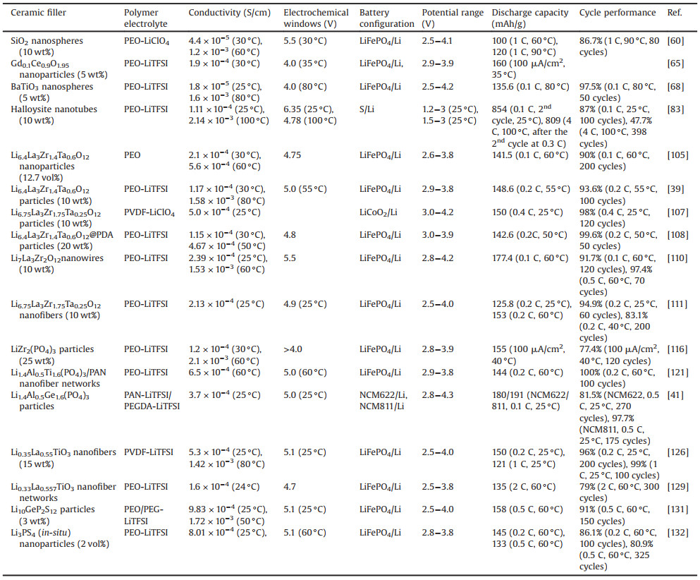
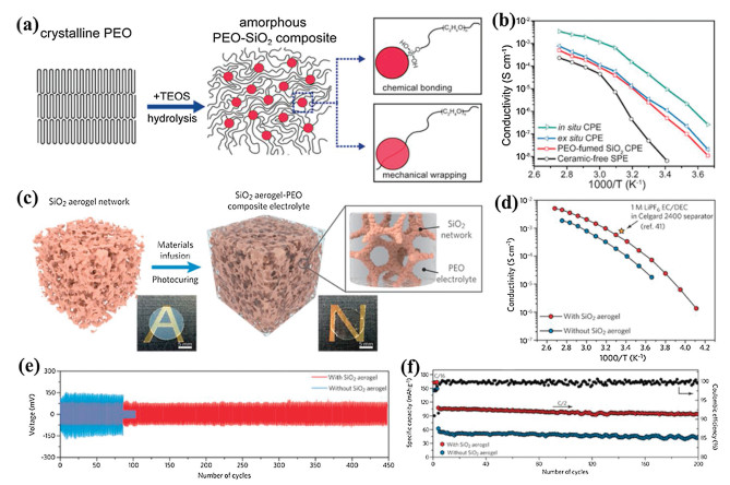
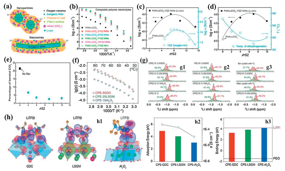
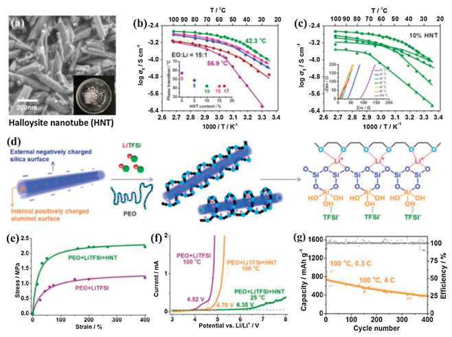
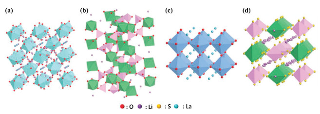
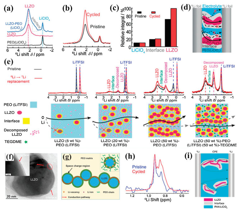
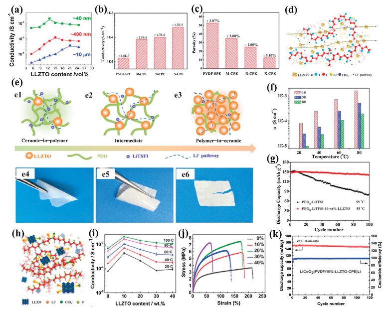
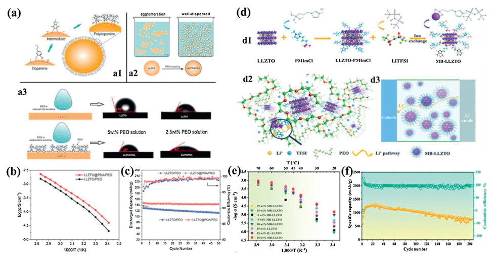
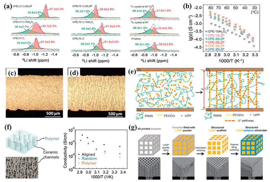
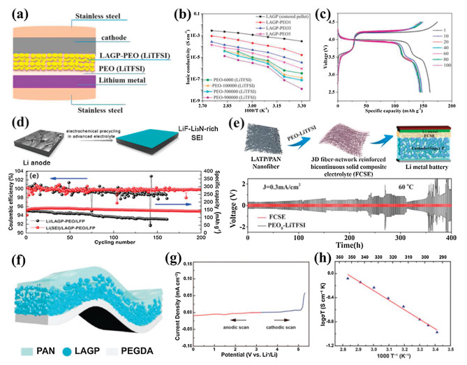
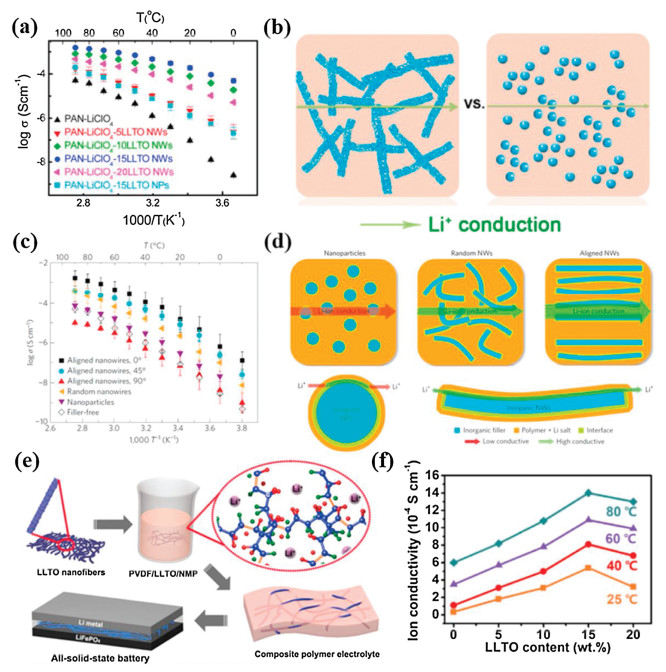
Although great endeavors have been devoted to developing CSPEs in ASSLBs, there are still some challenges regarding both fundamental understanding and practical applications to be overcome. Herein, according to the current existing issues of CSPEs in ASSLBs, the potential research directions are proposed for the future development of CSPEs.
First, in-depth comprehending of Li+ transfer mechanism is important for the development of high-performance CSPEs. The Li+ migration is very complex in the dual phase or multiphase system of CSPEs. It is necessary to understand the Li+ migration behavior and interactions between various components in CSPEs by the advanced in-situ characterization techniques and theoretical calculation, which can guide us to better construct high-performance CSPEs.
Second, achieving high ionic conductivity at ambient temperature comparable to that of liquid electrolytes is crucial for the practical applications of CSPEs in ASSLBs. Developing new components with high ionic conductivity, constructing continuous Li+ transfer channels by introducing active fillers with 3D framework, and enhancing the interactions between different components should be more effective strategies for high ionic conductive CSPEs. Additionally, high Li+ transference number is significant to reduce concentration polarization. For achieving a high Li+ transference number, the corresponding anions need to be physically and/or chemically immobilized by functional groups or skeletons from polymers or fillers, which can facilitate high-efficiency Li+ migration in CSPEs.
Third, optimizing the interfacial stability between CSPEs and electrodes is quite essential for high-performance ASSLBs. For high-voltage cathode/CSPEs interface, new voltage-resistance CSPEs or interfacial layers should be developed to improve the compatibility between the high-voltage cathodes and CSPEs. Moreover, in order to suppress the lithium dendrite formation and growth, the lithium metal anode/electrolyte interface with high ionic conductivity and high Li+ transference number should be built for the uniform lithium deposition. Additionally, constructing the intimate contact interfaces between CSPEs and electrodes is helpful to reduce the interfacial resistance and enhance the performance of ASSLBs.
Last, the mechanical strength of CSPEs has great influence on the performance of ASSLBs. The CSPEs with suitable mechanical strength can accommodate the volumetric expansion of active materials and maintain the close interfacial contact, as well as prevent being pierced by lithium dendrites. Thus, developing new polymer matrixes with proper mechanical strength and/or incorporating 3D hierarchical nanostructured fillers should raise more attentions.
Declaration of competing interestThe authors report no declarations of interest
AcknowledgmentThis work was supported by the Innovative and Entrepreneurial Talent Plan (Jiangsu Province, China).
| [1] |
M. Armand, J.M. Tarascon, Nature 451 (2008) 652-657. DOI:10.1038/451652a |
| [2] |
E. Quartarone, P. Mustarelli, Chem. Soc. Rev. 40 (2011) 2525-2540. DOI:10.1039/c0cs00081g |
| [3] |
M. Li, J. Lu, Z. Chen, K. Amine, Adv. Mater. 30 (2018) 1800561. DOI:10.1002/adma.201800561 |
| [4] |
J. Janek, W.G. Zeier, Nat. Energy 1 (2016) 16141. DOI:10.1038/nenergy.2016.141 |
| [5] |
F. Lv, Z. Wang, L. Shi, et al., J. Power Sources 441 (2019) 227175. DOI:10.1016/j.jpowsour.2019.227175 |
| [6] |
D. Lin, Y. Liu, Y. Cui, Nat. Nanotechnol. 12 (2017) 194-206. DOI:10.1038/nnano.2017.16 |
| [7] |
X.B. Cheng, R. Zhang, C.Z. Zhao, Q. Zhang, Chem. Rev. 117 (2017) 10403-10473. DOI:10.1021/acs.chemrev.7b00115 |
| [8] |
P. Zhai, L. Liu, X. Gu, T. Wang, Y. Gong, Adv. Energy Mater. (2020) 2001257. |
| [9] |
J.B. Goodenough, Y. Kim, Chem. Mater. 22 (2010) 587-603. DOI:10.1021/cm901452z |
| [10] |
L. Fan, S. Wei, S. Li, Q. Li, Y. Lu, Adv. Energy Mater. 8 (2018) 1702657. DOI:10.1002/aenm.201702657 |
| [11] |
Y. Zhang, T.T. Zuo, J. Popovic, et al., Mater. Today 33 (2020) 56-74. DOI:10.1016/j.mattod.2019.09.018 |
| [12] |
R. Xu, X.B. Cheng, C. Yan, et al., Matter 1 (2019) 317-344. DOI:10.1016/j.matt.2019.05.016 |
| [13] |
W. Liu, S.W. Lee, D. Lin, et al., Nat. Energy 2 (2017) 17035. DOI:10.1038/nenergy.2017.35 |
| [14] |
D. Li, L. Chen, T. Wang, L.Z. Fan, ACS Appl. Mater. Interfaces 10 (2018) 7069-7078. DOI:10.1021/acsami.7b18123 |
| [15] |
J.Y. Liang, X.X. Zeng, X.D. Zhang, et al., J. Am. Chem. Soc. 141 (2019) 9165-9169. DOI:10.1021/jacs.9b03517 |
| [16] |
R. Chen, Q. Li, X. Yu, L. Chen, H. Li, Chem. Rev. 120 (2020) 6820-6877. DOI:10.1021/acs.chemrev.9b00268 |
| [17] |
X.B. Cheng, C.Z. Zhao, Y.X. Yao, H. Liu, Q. Zhang, Chem 5 (2019) 74-96. DOI:10.1016/j.chempr.2018.12.002 |
| [18] |
H. Liu, X.B. Cheng, J.Q. Huang, et al., ACS Energy Lett. 5 (2020) 833-843. DOI:10.1021/acsenergylett.9b02660 |
| [19] |
L. Liu, J. Mo, J. Li, et al., J. Energy Chem. 48 (2020) 334-343. DOI:10.1016/j.jechem.2020.02.033 |
| [20] |
J. Janek, W.G. Zeier, Nat. Energy 1 (2016) 16141. DOI:10.1038/nenergy.2016.141 |
| [21] |
F. Wu, K. Zhang, Y. Liu, et al., Energy Storage Mater. 33 (2020) 26-54. DOI:10.1016/j.ensm.2020.08.002 |
| [22] |
A. Manthiram, X. Yu, S. Wang, Nat. Rev. Mater. 2 (2017) 16103. DOI:10.1038/natrevmats.2016.103 |
| [23] |
R. Murugan, V. Thangadurai, W. Weppner, Angew. Chem. Int. Ed. 46 (2007) 7778-7781. DOI:10.1002/anie.200701144 |
| [24] |
Y. Li, J.T. Han, C.A. Wang, H. Xie, J.B. Goodenough, J. Mater. Chem. 22 (2012) 15357-15361. DOI:10.1039/c2jm31413d |
| [25] |
B. Kumar, D. Thomas, J. Kumar, J. Electrochem. Soc 156 (2009) A506-A513. DOI:10.1149/1.3122903 |
| [26] |
K. Arbi, W. Bucheli, R. Jiménez, J. Sanz, J. Eur. Ceram. Soc. 35 (2015) 1477-1484. DOI:10.1016/j.jeurceramsoc.2014.11.023 |
| [27] |
Y. Inaguma, L. Chen, M. Itoh, et al., Solid State Ion. 86 (1993) 689-693. |
| [28] |
J.F. Wu, X. Guo, Phys. Chem. Phys. Chem. 19 (2017) 5880-5887. DOI:10.1039/C6CP07757A |
| [29] |
Y. Li, W. Zhou, X. Chen, et al., Proc. Natl. Acad. Sci. U. S. A. 113 (2016) 13313-13317. DOI:10.1073/pnas.1615912113 |
| [30] |
H. Huo, Y. Chen, R. Li, et al., Energy Environ. Sci. 13 (2020) 127-134. DOI:10.1039/C9EE01903K |
| [31] |
N. Kamaya, K. Homma, Y. Yamakawa, et al., Nat. Mater. 10 (2011) 682-686. DOI:10.1038/nmat3066 |
| [32] |
Y. Kato, S. Hori, T. Saito, et al., Nat. Energy 1 (2016) 16030. DOI:10.1038/nenergy.2016.30 |
| [33] |
X. Li, Z. Ren, M.N. Banis, et al., ACS Energy Lett. 4 (2019) 2480-2488. DOI:10.1021/acsenergylett.9b01676 |
| [34] |
Q. Lu, Y.B. He, Q. Yu, et al., Adv. Mater. 29 (2017) 1604460. DOI:10.1002/adma.201604460 |
| [35] |
Q. Wang, S.L. Song, L.Z. Fan, Y. Song, J. Membr. Sci. 492 (2015) 490-496. DOI:10.1016/j.memsci.2015.06.041 |
| [36] |
P.J. Alacro, Y. Abu-Lebdeh, A. Abouimrane, M. Armand, Nat. Mater. 3 (2004) 476-481. DOI:10.1038/nmat1158 |
| [37] |
D. Lin, P.Y. Yuen, Y. Liu, et al., Adv. Mater. 30 (2018) 1802661. DOI:10.1002/adma.201802661 |
| [38] |
X. Lin, J. Wang, J.D. Miller Liu, Nano Energy 31 (2017) 478-485. DOI:10.1016/j.nanoen.2016.11.045 |
| [39] |
L. Chen, Y. Li, S.P. Li, et al., Nano Energy 46 (2018) 176-184. DOI:10.1016/j.nanoen.2017.12.037 |
| [40] |
K. Fu, Y. Gong, J. Dai, et al., Proc. Natl. Acad. Sci. U. S. A. 113 (2016) 7094-7099. DOI:10.1073/pnas.1600422113 |
| [41] |
H. Duan, M. Fan, W.P. Chen, et al., Adv. Mater. 31 (2019) 1807789. DOI:10.1002/adma.201807789 |
| [42] |
L. Li, Y. Deng, G. Chen, J. Energy Chem. 50 (2020) 154-177. DOI:10.1016/j.jechem.2020.03.017 |
| [43] |
B. Zhao, X. Lu, Q. Wang, et al., Chin. Chem. Lett. 31 (2020) 831-835. DOI:10.1016/j.cclet.2019.06.009 |
| [44] |
W. Wieczorek, J.R. Stevens, Z. Florjanczyk, Solid State Ion. 85 (1996) 67-72. DOI:10.1016/0167-2738(96)00042-2 |
| [45] |
F. Croce, R. Curini, A. Martinelli, etal., J.Phys.Chem.B 103 (1999) 10632-10638. DOI:10.1021/jp992307u |
| [46] |
F. Croce, L. Persi, B. Scrosati, et al., Electrochim. Acta 46 (2001) 2457-2461. DOI:10.1016/S0013-4686(01)00458-3 |
| [47] |
D.E. Fenton, J.M. Parker, P.V. Wright, Polymer 14 (1973) 589-590. DOI:10.1016/0032-3861(73)90146-8 |
| [48] |
D. Devaux, R. Bouchet, D. Gle, R. Denoyel, Solid State Ion. 227 (2012) 119-127. DOI:10.1016/j.ssi.2012.09.020 |
| [49] |
Z. Xue, D. He, X. Xie, J. Mater, Chem. A 3 (2015) 19218-19253. DOI:10.1039/C5TA03471J |
| [50] |
P. Johansson, Polymer 42 (2001) 4367-4373. DOI:10.1016/S0032-3861(00)00731-X |
| [51] |
F.B. Dias, L. Plomp, J.B.J. Veldhuis, J. Power Source 88 (2000) 169-191. DOI:10.1016/S0378-7753(99)00529-7 |
| [52] |
R. Bouchet, S. Maria, R. Meziane, et al., Nat. Mater. 12 (2013) 452-457. DOI:10.1038/nmat3602 |
| [53] |
J.E. Weston, B.C.H. Steele, Solid State Ion. 7 (1982) 75-79. DOI:10.1016/0167-2738(82)90072-8 |
| [54] |
F. Croce, G.B. Appetecchi, L. Persi, B. Scrosati, Nature 384 (1998) 456-458. DOI:10.1038/28818 |
| [55] |
F. Croce, F. Bonino, S. Panero, B. Scrosati, Phil. Mag. B 59 (1989) 161-168. DOI:10.1080/13642818908208455 |
| [56] |
F. Capuano, F. Croce, B. Scrosati, J. Electrochem. Soc. 52 (1991) 1918-1922. DOI:10.1149/1.2085900 |
| [57] |
J. Przyluski, M. Siekierski, W. Wieczorek, Electrochim. Acta 40 (1995) 2101-2108. DOI:10.1016/0013-4686(95)00147-7 |
| [58] |
G. Jiang, S. Maeda, H. Yang, et al., J. Power Source 141 (2005) 143-148. DOI:10.1016/j.jpowsour.2004.09.004 |
| [59] |
S. Liu, N. Imanishi, T. Zhang, et al., J. Power Source 195 (2010) 6847-6853. DOI:10.1016/j.jpowsour.2010.04.027 |
| [60] |
D. Lin, W. Liu, Y. Liu, et al., Nano Lett. 16 (2016) 459-465. DOI:10.1021/acs.nanolett.5b04117 |
| [61] |
W. Liu, D. Lin, J. Sun, G. Zhou, Y. Cui, ACS Nano 10 (2016) 11407-11413. DOI:10.1021/acsnano.6b06797 |
| [62] |
B.C.H. Steele, A. Heinzel, Nature 414 (2001) 345-352. DOI:10.1038/35104620 |
| [63] |
V.V. Kharton, F.M.B. Marques, A. Atkinson, Solid State Ion. 174 (2004) 135-149. DOI:10.1016/j.ssi.2004.06.015 |
| [64] |
J.B. Goodenough, Annu. Rev. Mater. Res. 33 (2003) 91-128. DOI:10.1146/annurev.matsci.33.022802.091651 |
| [65] |
N. Wu, P.H. Chien, Y. Qian, et al., Angew. Chem. 132 (2020) 4160-4166. DOI:10.1002/ange.201914478 |
| [66] |
H.Y. Sun, H.J. Sohn, O. Yamamoto, Y. Takeda, N. Imanishi, J. Electrochem. Soc. 146 (1999) 1672-1676. DOI:10.1149/1.1391824 |
| [67] |
H.Y. Sun, Y. Takeda, N. Imanishi, et al., J. Electrochem. Soc. 147 (2000) 2462-2467. DOI:10.1149/1.1393554 |
| [68] |
T. Itoh, Y. Ichikawa, T. Uno, M. Kubo, O. Yamamoto, Solid State Ion. 156 (2003) 393-399. DOI:10.1016/S0167-2738(02)00682-3 |
| [69] |
Y. Zhang, X. Wang, W. Feng, et al., Ionics 25 (2019) 1471-1480. DOI:10.1007/s11581-018-2706-0 |
| [70] |
Y. Zhang, X. Wang, W. Feng, et al., J. Solid Sate Electrochem. 23 (2019) 749-758. DOI:10.1007/s10008-018-04175-4 |
| [71] |
Z. Zhang, Q. Wang, Z. Li, et al., Mater. Express 9 (2019) 993-1000. DOI:10.1166/mex.2019.1589 |
| [72] |
H.W. Chen, F.C. Chang, J. Polym.Sci. PartB: Polym.Phys. 39 (2001) 2407-2419. DOI:10.1002/polb.1212 |
| [73] |
J.J. Hwang, H.J. Liu, Macromolecules 35 (2002) 7314-7319. DOI:10.1021/ma020613r |
| [74] |
S. Kim, S.J. Park, Solid State Ion. 178 (2007) 973-979. DOI:10.1016/j.ssi.2007.03.008 |
| [75] |
M. Wang, S. Dong, J. Power Sources 170 (2007) 425-432. DOI:10.1016/j.jpowsour.2007.04.031 |
| [76] |
N. Shukla, A.K. Thakur, Solid State Ion. 181 (2010) 921-932. DOI:10.1016/j.ssi.2010.05.023 |
| [77] |
R. Prasanth, N. Shubha, H.H. Hng, M. Srinivasan, Europ. Polym. J. 49 (2013) 307-318. DOI:10.1016/j.eurpolymj.2012.10.033 |
| [78] |
Y. Zhang, Y. Zhao, D. Gosselink, P. Chen, Ionics 21 (2015) 381-385. DOI:10.1007/s11581-014-1176-2 |
| [79] |
Y. Ma, L.B. Li, G.X. Gao, X.Y. Yang, Y. You, Electrochim. Acta 187 (2016) 535-542. DOI:10.1016/j.electacta.2015.11.099 |
| [80] |
M. Du, B. Guo, D. Jia, Polym. Int. 59 (2010) 574-582. DOI:10.1002/pi.2754 |
| [81] |
V. Gupta, M.A. Hampton, A.V. Nguyen, J.D. Miller, J. Colloid Interface Sci. 352 (2010) 75-80. DOI:10.1016/j.jcis.2010.08.002 |
| [82] |
J. Tully, R. Yendluri, Y. Lvov, Biomacromolecules 17 (2016) 615-621. DOI:10.1021/acs.biomac.5b01542 |
| [83] |
Y. Lin, X. Wang, J. Liu, J.D. Miller, Nano Energy 31 (2017) 478-485. DOI:10.1016/j.nanoen.2016.11.045 |
| [84] |
Q. Zhu, X. Wang, J.D. Miller, ACS Appl. Mater. Interface 11 (2019) 8954-8960. DOI:10.1021/acsami.8b13735 |
| [85] |
Y. Liu, P. He, H. Zhou, Adv. Energy Mater. 8 (2017) 1701602. |
| [86] |
V. Thangadurai, S. Narayanan, D. Pinzaru, Chem. Soc. Rev. 43 (2014) 4714-4727. DOI:10.1039/c4cs00020j |
| [87] |
V. Thangadurai, H. Kaack, W.J.F. Weppner, J. Am. Ceram. Soc. 86 (2003) 437-440. DOI:10.1111/j.1151-2916.2003.tb03318.x |
| [88] |
J.L. Allen, J. Wolfenstine, E. Rangasamy, J. Sakamoto, J. Power Sources 206 (2012) 315-319. DOI:10.1016/j.jpowsour.2012.01.131 |
| [89] |
C. Deviannapoorani, L. Dhivya, S. Ramakumar, R. Murugan, J. Power Sources 240 (2013) 18-25. DOI:10.1016/j.jpowsour.2013.03.166 |
| [90] |
S. Ohta, T. Kobayashi, T. Asaoka, J. Power Sources 196 (2011) 3342-3345. DOI:10.1016/j.jpowsour.2010.11.089 |
| [91] |
Y. Wang, W. Lai, Electronchem. Solid-State Lett. 15 (2012) A68-A71. DOI:10.1149/2.024205esl |
| [92] |
J.B. Goodenough, H.Y.P. Hong, J.A. Kafalas, Mat. Res. Bull. 11 (1976) 203-220. DOI:10.1016/0025-5408(76)90077-5 |
| [93] |
H. Aono, Acc. Chem. Res. 27 (1994) 265-270. DOI:10.1021/ar00045a002 |
| [94] |
T. Takahashi, H. Iwahara, Energy Convers. 11 (1971) 105-111. DOI:10.1016/0013-7480(71)90121-5 |
| [95] |
S. Stramare, V. Thangadurai, W. Weppner, Chem. Mater. 15 (2003) 3974-3990. DOI:10.1021/cm0300516 |
| [96] |
R. Kanno, M. Murayama, J. Electrochem. Soc. 148 (2001) A742-A746. DOI:10.1149/1.1379028 |
| [97] |
A. Hayashi, S. Hama, H. Morimoto, M. Tatsumisago, T. Minami, J. Am. Ceram. Soc. 84 (2001) 477-479. DOI:10.1111/j.1151-2916.2001.tb01141.x |
| [98] |
F. Mizuno, A. Hayashi, K. Tadanaga, M. Tatsumisago, Solid State Ion. 177 (2006) 2721-2725. DOI:10.1016/j.ssi.2006.04.017 |
| [99] |
Y. Seino, T. Ota, K. Takada, A. Hayashi, M. Tatsumisago, Energy Environ. Sci. 7 (2014) 627-631. DOI:10.1039/C3EE41655K |
| [100] |
J. Haruyama, K. Sodeyama, L. Han, K. Takada, Y. Tateyama, Chem. Mater. 26 (2014) 4248-4255. DOI:10.1021/cm5016959 |
| [101] |
J. Zheng, M. Tang, Y.Y. Hu, Angew. Chem. Int. Ed. 55 (2016) 12538-12542. DOI:10.1002/anie.201607539 |
| [102] |
J. Zheng, Y.Y. Hu, ACS Appl. Mater. Interfaces 10 (2018) 4113-4120. DOI:10.1021/acsami.7b17301 |
| [103] |
Z. Li, H.M. Huang, J.K. Zhu, et al., ACS Appl. Mater. Interfaces 11 (2019) 784-791. DOI:10.1021/acsami.8b17279 |
| [104] |
T. Yang, J. Zheng, Q. Cheng, Y.Y. Hu, C.K. Chan, ACS Appl. Mater. Interfaces 9 (2017) 21773-21780. DOI:10.1021/acsami.7b03806 |
| [105] |
J. Zhang, N. Zhao, M. Zhang, et al., Nano Energy 28 (2016) 447-454. DOI:10.1016/j.nanoen.2016.09.002 |
| [106] |
Y. Sun, X. Zhan, J. Hu, et al., ACS Appl. Mater. Interfaces 11 (2019) 12467-12475. DOI:10.1021/acsami.8b21770 |
| [107] |
X. Zhang, T. Liu, S. Zhang, et al., J. Am. Chem. Soc. 139 (2017) 13779-13785. DOI:10.1021/jacs.7b06364 |
| [108] |
Z. Huang, W. Pang, P. Liang, et al., J. Mater. Chem. A 7 (2019) 16425-16436. DOI:10.1039/C9TA03395E |
| [109] |
W. Li, C. Sun, J. Jin, et al., J. Mater. Chem. A 7 (2019) 27304-27312. DOI:10.1039/C9TA10400C |
| [110] |
Z. Wan, D. Lei, W. Yang, et al., Adv. Funct. Mater. 29 (2018) 1805301. |
| [111] |
R. Fan, C. Liu, K. He, et al., ACS Appl. Mater. Interfaces 12 (2020) 7222-7231. DOI:10.1021/acsami.9b20104 |
| [112] |
Y. Zhao, J. Yan, W. Cai, et al., Energy Storage Mater. 23 (2019) 306-313. DOI:10.1016/j.ensm.2019.04.043 |
| [113] |
Y.J. Wang, Y. Pan, L. Chen, Mater. Phys. Chem. 92 (2005) 354-360. DOI:10.1016/j.matchemphys.2004.12.004 |
| [114] |
Y.J. Wang, Y. Pan, D. Kim, J. Power Sources 159 (2006) 690-701. DOI:10.1016/j.jpowsour.2005.10.104 |
| [115] |
W. Wang, E. Yi, A.J. Fici, R.M. Laine, J. Kieffer, J. Phys. Chem. C 121 (2017) 2563-2573. DOI:10.1021/acs.jpcc.6b11136 |
| [116] |
N. Wu, P.H. Chien, Y. Li, et al., J. Am. Chem. Soc. 142 (2020) 2497-2505. DOI:10.1021/jacs.9b12233 |
| [117] |
X. Liu, S. Peng, S. Gao, et al., ACS Appl. Mater. Interfaces 10 (2018) 15691-15696. DOI:10.1021/acsami.8b01631 |
| [118] |
H. Zhai, P. Xu, M. Ning, et al., Nano Lett. 17 (2017) 3182-3187. DOI:10.1021/acs.nanolett.7b00715 |
| [119] |
S. Zekoll, C. Marriner-Edwards, A.K.O. Hekselman, et al., Energy Environ. Sci. 11 (2018) 185-201. DOI:10.1039/C7EE02723K |
| [120] |
C. Wang, Y. Yang, X. Liu, et al., ACS Appl. Mater. Interfaces 9 (2017) 13694-13702. DOI:10.1021/acsami.7b00336 |
| [121] |
G. Hou, X. Ma, Q. Sun, et al., ACS Appl. Mater. Interfaces 10 (2018) 18610-18618. DOI:10.1021/acsami.8b01003 |
| [122] |
D. Li, L. Chen, T. Wang, L.Z. Fan, ACS Appl. Mater. Interfaces 10 (2018) 7069-7078. DOI:10.1021/acsami.7b18123 |
| [123] |
W. Liu, N. Liu, J. Sun, et al., Nano Lett. 15 (2015) 2740-2745. DOI:10.1021/acs.nanolett.5b00600 |
| [124] |
W. Liu, S.W. Lee, D. Lin, et al., Nat. Energy 2 (2017) 17035. DOI:10.1038/nenergy.2017.35 |
| [125] |
P. Zhu, C. Yan, M. Dirican, et al., J. Mater. Chem. A 6 (2018) 4279-4285. DOI:10.1039/C7TA10517G |
| [126] |
B. Li, Q. Su, L. Yu, et al., ACS Appl. Mater. Interfaces 11 (2019) 42206-42213. DOI:10.1021/acsami.9b14824 |
| [127] |
J. Bae, Y. Li, J. Zhang, et al., Angew. Chem. Int. Ed. 57 (2018) 2096-2100. DOI:10.1002/anie.201710841 |
| [128] |
X. Wang, Y. Zhang, X. Zhang, et al., ACS Appl. Mater. Interfaces 10 (2018) 24791-24798. DOI:10.1021/acsami.8b06658 |
| [129] |
D. Liu, R. Zhang, J. Sun, M. Wu, T. Zhao, ACS Appl. Mater. Interfaces 11 (2019) 46930-46937. DOI:10.1021/acsami.9b16936 |
| [130] |
Y. Zhao, C. Wu, G. Peng, et al., J. Power Sources 301 (2016) 47-53. DOI:10.1016/j.jpowsour.2015.09.111 |
| [131] |
K. Pan, L. Zhang, W. Qian, et al., Adv. Mater. 32 (2020) 2000399. DOI:10.1002/adma.202000399 |
| [132] |
S. Chen, J. Wang, Z. Zhang, et al., J. Power Sources 387 (2018) 72-80. DOI:10.1016/j.jpowsour.2018.03.016 |