 2021, Vol. 32


b Key Laboratory of High-Performance Fibers & Products, Ministry of Education, Donghua University, Shanghai 201620, China;
c Zhejiang Provincial Key Laboratory of Yarn Material Forming and Composite Processing Technology, Jiaxing University, Jiaxing 314001, China
With the development of portable electronic products, it is particularly important to design and manufacture lightweight and flexible energy storage devices in order to cater to and meet market demand. As an energy storage device, flexible supercapacitor has attracted much attention in recent years due to its long cycle life, moderate energy/power density and stable operation performance. On the basis of the energy storage mechanism, supercapacitors were split into two different types: electrical double-layer capacitors (EDLCs) and pseudo-capacitors, which accumulated energy through fast physical adsorption/desorption ions on the electrode/electrolyte interface and rapid and reversible redox reactions, respectively. Up to date, the electrode material is still a vital factor to determine the performance of supercapacitors.
Graphene, carbon nanotubes (CNTs), carbon sphere, and other carbon materials with a variety of nanostructures and high accessible surface area have been widely used in EDLCs electrode materials. However, the materials mentioned above do not have high specific capacity and excellent rate capability, which made them unable to be directly used as flexible electrode materials. Additionally, the high cost of carbon nanotubes and graphene also limited their large-scale industrial application. The electrode with high specific capacity and good rate performance become the key factor of ideal flexible supercapacitor. In contrast, the freestanding carbon nanofibers (CNFs) with low cost, high conductivity, and flexibility were easier to be synthesized and used as flexible electrodes directly. Liu et al. [1] prepared a flexible composite carbon nanofiber membrane based on polypyrrole/polyimide with a specific capacitance of 172.44 F/g at 200 mA/g. Subsequently, a flexible micro-/mesoporous carbon nanofiber was synthesized as electrodes with a specific capacitance of ~241.4 F/g at 1 A/g [2]. These research results also exposed the defect that carbon nanofiber electrodes have lower specific capacitance. Generally, the combination of carbon nanofibers and conductive polymers or transition metal oxides was used to increase the specific capacitances in order to effectively solve this problem [3-6]. Among them, polyaniline (PANI), which has the advantages of low cost, high conductivity, large energy storage capacity as well as controllable conductivity, has been selected as a promising candidate material [7-9]. For example, Yan et al. [10] reported a CNFs/PANI nanoparticles composite with high specific capacitances of 1050 F/g at 1 A/g.
However, when the current density is up to 5 A/g, the specific capacitance quickly decreases to 350 F/g. Song et al. [11] synthesized needle-like polyaniline nanowire on the coal-based carbon nanofibers with a low specific capacitance of 458 F/g at 0.5 A/g, the retention of specific capacitance is only 87% at 2 A/g after 1000 cycles. Tian et al. [7] prepared a hybrid carbon nanofiber composite/polyaniline by electrospinning and in-situ polymerization methods, which exhibits a specific capacitance of 318.0 F/g at 0.5 A/g. The symmetric supercapacitor of Ni-G-CNFs/PANI only maintains the capacitance retentions of 76.3% after 1000 cycles 1 A/g. For instance, Ke et al. [12] reported aminated triazine functionalized carbon fiber/PANI composites (PANI/ATFCF) as an electrode for supercapacitors, which show a specific capacitance of 456.73 F/g at 1 A/g and 84.19% capacitance retentions after 1500 cycles at 100 mV/s. The flexible PVA/CNT/PANI membrane was prepared as supercapacitor electrodes with 89.3% capacitance retention after 2000 cycles [13]. Apparently, both the specific capacity and cycling stability of CNFs/PANI composites is not good enough for wearable electronics. Hence, to get flexible supercapacitors with high specific capacity and ultra-long cycle performance, it is extremely essential to establish a hollow connectivity channel for PANI that could promote the fast kinetics diffusion of the electrolyte ions in contact electrodes.
In this work, a flexible hollow carbon nanofiber was designed via an electrospinning method. The hollow structure in the interconnected carbon nanofibers can only improve the mass loading of PANI but also increase the effective contact area between the electrodes and the electrolytes and confine the volume expansion of PANI during the electrochemical process [14, 15]. The ordered needle-shaped PANI were grown on the inside and outside of HCNFs uniformly by in-situ polymerization to prepare flexible the HCNFs/PANI composites. The HCNFs/PANI composites revealed a high capacity 1196.7 F/g at 1 A/g and good cycling stability with 90.1% retention at a higher current density of 5 A/g after 3000 cycles. More importantly, the symmetric supercapacitor (SC) assembled using HCNFs/PANI composites as electrodes displayed a high energy density of 60.28 Wh/kg at 1000 W/kg and superior cycling stability with 90% retention after 3000 cycles at 5 A/g.
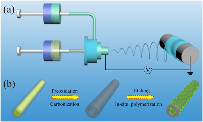
Scheme 1 typically shows the preparation of HCNFs/PANI composites. First of all, a piece of fibrous film was synthesized by a coaxial electrospinning method (Scheme 1a). After that, the electrospun film was subjected to peroxidation in air and carbonization in N2 to obtain HCNFs. The resultant HCNFs was further etched in 1 mol/L H2SO4 aqueous solution by an electrochemical etching method to active HCNFs. Finally, the freestanding HCNFs/PANI composite was synthesized through the in-situ polymerization method (Scheme 1b), which exhibited excellent flexibility in Fig. S1 (Supporting information).

|
Download:
|
| Scheme 1. (a) Schematic of the electrospinning process of P(AN-co-MHI)/SAN composited fibers. (b) Schematic illustration of preparing HCNFs/PANI composites. | |
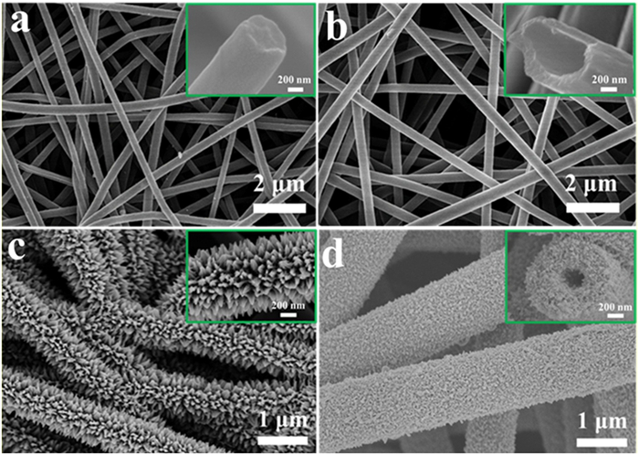
As illustrated in Fig. 1, the morphology and structure of CNFs, HCNFs, CNFs/PANI and HCNFs/PANI composites were characterized by SEM. It could be observed from Figs. 1a and b that CNFs and HCNFs present typically interconnection networks with diameters of 600 nm and 700 nm, respectively, which provided a good conductive path for electrons. Furthermore, the acid-treated HCNFs showed a clear hollow structure compared with CNFs (observed in the inset in Fig. 1b). As depicted in Figs. 1c and d, the needle-like PANI was vertically anchored on the outer surface of CNFs and HCNFs respectively after in-situ polymerization of aniline. Obviously, both the inside and outside of HCNFs are covered by PANI, which could effectively improve the mass loading of PANI. The hollow structures have displayed great structural superiority for supercapacitors because the hollow structure of HCNFs can provide a high surface area and short transportation distance for both mass and charge. Based on TG data in Fig. S2 (Supporting information), the mass loading of PANI in CNFs/PANI, and HCNFs/PANI composites were 39.37 wt% and 46.52 wt%, respectively. The specific surface area of HCNFs was 2.03 times of CNFs (Fig. S3 in Supporting information). The microstructure of CNFs/PANI and HCNFs/PANI composites were characterized by TEM and shown in Fig. S4 (Supporting information). The needle-like PANI was homogeneously decorated on the surface of CNFs and HCNFs. The hollow structure of HCNFs/PANI with diameter ca. 450 nm can be clearly seen in the Fig. S4b and this unique hollow structure can alleviate the volume expansion during charging/discharging process effectively. Besides, before polymerization of aniline, the CNFs and HCNFs were electrochemical etched, the water contact angle decreases from 141° to 65° as shown in Fig. S5 (Supporting information), indicating that electrochemical etching could increase the hydrophilicity of HCNFs. More importantly, the electrochemical etching could provide abundant nucleation points for aniline polymerization.

|
Download:
|
| Fig. 1. SEM images of (a and inset) CNFs, (b and inset) HCNFs, (c and inset) CNFs/PANI, and (d and inset) HCNFs/PANI composites. | |
The XRD patterns of CNFs, HCNFs, PANI, CNFs/PANI and HCNFs/PANI were presented in Fig. 2a. Both CNFs and HCNFs reveal two broad diffraction peaks at 25.3° and 42.4°, which were in keeping with amorphous carbon [11, 16]. The crystalline peaks of pure PANI emerging at 2θ = 19.0° and 25.7° are ascribed to (020) and (200) diffraction planes of PANI, respectively [17, 18]. Compared with pure PANI, the HCNFs/PANI and CNFs/PANI composites present similar characteristic peaks, indicating PANI were coated on carbon nanofibers successfully. The Raman spectra of samples are shown in Fig. 2b, there are two obvious characteristic peaks at 1323 and 1581 cm−1 for CNFs and HCNFs, corresponding to the disordered carbonaceous matrix (D peak) and ordered graphitized structure (G peak) [14, 19]. For PANI, the characteristic peaks appearing at 1169 cm−1, 1349 cm−1, 1505 cm−1 and 1590 cm−1 belong to C–H stretching of the benzene ring, protonated CN stretching, C=N stretching vibration, and C-C stretching of benzene/quinoid ring, respectively [20, 21]. Furthermore, similar characteristic peaks were also shown in HCNFs/PANI and CNFs/PANI composites, confirming PANI was composited with CNFs and HCNFs successfully. The FTIR spectra of resultant samples are presented in Fig. 2c, the absorption peaks around 3429 cm−1 of all samples belong to the −OH. There are two stretching vibration peaks at 1641 cm−1 (C=C) and 1384 cm−1 (C–C) for CNFs and HCNFs [11]. The absorption peaks at 1585, 1507, 1300 and 1045 cm−1 are attributed to the stretching vibrations of C=C in the benzene/quinoid ring, aromatic C-N, and C–H stretching vibrations in the FTIR spectrum of PANI [22, 23]. The characteristic peaks of PANI can be clearly observed in HCNFs/PANI and CNFs/PANI. The XPS spectrum of HCNFs/PANI composites is shown in Fig. 2d. Obviously, there are three peaks of C, N and O elements in the XPS full spectrum. In the C 1s spectrum (Fig. 2e), there are three main peaks at 284.7, 285.6 and 286.6 eV, which belong to the C–C/C=C, C–N/C=N and C–O bands, respectively [7, 24]. For N 1s spectrum (Fig. 2f), the peak with binding energy at 399.9 eV is attributed to quinoid imine (=N-), and the typical characteristic peak at 401.4 eV belongs to benzenoid amine (-NH-) [7, 25, 26]. The XPS results further confirm the successful preparation of HCNFs/PANI composites.

|
Download:
|
| Fig. 2. (a) XRD curves, (b) Raman spectra and (c) FTIR spectra of all the samples. XPS spectra of the HCNFs/PANI composites: (d) the full survey spectrum, (e) C 1s, (f) N 1s. | |
The electrochemical performance of the HCNFs/PANI and CNFs/PANI composites were measured in a three-electrode configuration. Figs. 3a-c show the typical cyclic voltammetry (CV) profile and galvanostatic charge/discharge (GCD) curves of the HCNFs/PANI and CNFs/PANI composite electrodes. The CV curves of HCNFs/PANI and CNFs/PANI composites at various sweep rates from 20 mV/s to 100 mV/s were performed (Fig. 3a and Fig. S6 in Supporting information) and the current response increases with the increase of sweep rates. Besides, the CV profiles for both HCNFs/PANI and CNFs/PANI are almost rectangular shapes, indicating excellent capacitive characteristics and rapid response on the reverse voltage at each end potential [27, 28]. The representative CV curves of the CNFs/PANI and HCNFs/PANI composites at the scan rate of 100 mV/s are shown in Fig. S7 (Supporting information). Obviously, the areas under the CV curve of HCNFs/PANI composites are much larger than the CNFs/PANI composites, indicating larger specific capacitance and enhanced energy storage ability of HCNFs/PANI, which is ascribed to the enlarged accessible surface areas of PANI with electrolyte.

|
Download:
|
| Fig. 3. (a) CV curves of HCNFs/PANI composites at different scan rates. (b) GCD curves of HCNFs/PANI composites at different current densities. (c) GCD curves of CNFs/PANI and HCNFs/PANI composites at 1 A/g. (d) Specific capacitances of CNFs/PANI and HCNFs/PANI composites at different current densities. (e) Cycling stability of CNFs/PANI and HCNFs/PANI composites at 5 A/g. (f) CV curves of the SC at different potential ranges at 60 mV/s. (g) CV curves of the SC at various scan rates from 20 mV/s to 100 mV/s. (h) GCD curves of the SC at various current densities. (i) Ragone plots of the SC and other previously reported PANI-based symmetric supercapacitor. | |
The GCD curves of the HCNFs/PANI and CNFs/PANI composites at various current densities from 1 A/g to 5 A/g are presented in Fig. 3b and Fig. S8 (Supporting information). The GCD curves of two electrodes exhibit a symmetrical triangle shape without an obvious IR drop, implying that excellent reversibility and small internal resistance [29]. The HCNFs/PANI composites achieve much longer discharge time and higher specific capacitance (1196.7 F/g) compared with CNFs/PANI composites (607.5 F/g) at 1 A/g (Fig. 3c), corresponding to the results given in Fig. S7, which also is the largest capacitance among the reported PANI-based electrode (Table S1 in Supporting information). Even at a large current density of 5 A/g, the HCNFs/PANI electrodes also present a high specific capacitance (578.7 F/g) as shown in Fig. 3d, which is attributed to the hollow structure of HCNFs and the large contact area between electrodes and electrolyte. Moreover, the HCNFs/PANI composites exhibit long-term cycling stability with capacitance retention of 90.1% (3000th versus 1st) at 5 A/g after 3000 cycles (Fig. 3e), which is larger than that (85.3%) of the CNFs/PANI because the hollow structure of HCNFs can confine the volume expansion of PANI during the charging/discharging process. The Nyquist plots of CNFs/PANI and HCNFs/PANI composites were split into a high-frequency semicircle and low-frequency straight line [2, 30] as shown in Fig. S9 (Supporting information), which were in accordance with interfacial charge transfer resistance (Rct) and Warburg resistance (Rw), respectively. Obviously, the Rct of CNFs/PANI composites is larger than that of HCNFs/PANI composites, revealing the ideal capacitive behavior. This may be ascribed to the needle-like PANI uniformly distributed on the inner and outside of HCNFs, which offers more exposed active sites of HCNFs/PANI to the electrolyte and establish a hollow connectivity channel for the fast kinetics diffusion of the electrolyte ions in contact electrodes. From the low-frequency region, HCNFs/PANI shows a nearly vertical line in the Warburg region without kinetic limitation of fast ion transport at the electrode-electrolyte interface, which is a key factor of fast energy storage capabilities.
To verify its application as electrodes for supercapacitor, a symmetrical supercapacitor (SC) was fabricated using two pieces of HCNFs/PANI composites (2 × 1 cm2) as anodic and cathodic electrodes in 1 mol/L H2SO4 aqueous electrolyte. The CV profiles of SC at 60 mV/s at various potential ranges are presented in Fig. 3f, all the curves almost exhibit rectangular shape in the voltage of 0.6~1.2 V, indicating that the SC shows ideal capacitive behavior with a fast I–V response and low equivalent series resistance of electrodes. The HCNFs/PANI were tested at different scaring rates (20−100 mV/s) in Fig. 3g, the CV profiles of SC can hold rectangular shape without obvious change even up to 100 mV/s, which further demonstrates an ideal capacitive behavior and efficient charge transfer kinetics of the SC. The GCD curves of SC at different current densities are demonstrated in Fig. 3h. The curves of SC are nearly triangular shapes, which demonstrates the excellent electrochemical reversibility of SC. The energy density and power density were calculated based on Fig. 3i, the SC can deliver a high energy density of 60.28 Wh/kg at 1000 W/kg, which are much larger than that of other reported works [7, 31-37]. The hollow structure of HCNFs can increase the deposition of PANI and offer fast kinetic diffusion of the electrolyte ion in compact electrodes. The cycling durability of the SC was conducted at 5 A/g up to 3000 cycles (Fig. S10 in Supporting information), which shows good long-life cycling stability with a retention of 90% (3000th versus 1st).
In summary, the flexible HCNFs/PANI composites were synthesized via simple electrospinning and in-situ polymerization methods and exhibited good electrochemical performance with the capacitance of 1196.7 F/g at 1 A/g and 90.1% capacity retention after 3000 cycles at a large current density of 5 A/g. The needle-like PANI, which was uniformly distributed on the inner and outside of HCNFs, provided more exposed active sites to the electrolyte and established a hollow connectivity channel that could promote the fast kinetics diffusion of the electrolyte ions in contact electrodes. Additionally, the symmetrical supercapacitor using HCNFs/PANI as electrodes delivered a high energy density of 60.28 Wh/kg at 1000 W/kg and superior cycling durability with a retention of 90% (3000th versus 1st) after 3000 cycles at 5 A/g. Therefore, the HCNFs/PANI composites could be served as prospective electrode material in energy storage.
Declaration of competing interestThe authors declared that they have no conflicts of interest to this work.
AcknowledgmentsThis work was supported by Fundamental Research Funds for the Central Universities (No. 2232019A3-11), National Natural Science Foundation of China (No. 51503086), Zhejiang Provincial Natural Science Foundation (No. LQ19E030014), and Open Project Program of Key Laboratory of Yarn Materials Forming and Composite Processing Technology of Zhejiang Province (No. MTC2019-13).
Appendix A. Supplementary dataSupplementarymaterial related to this article canbefound, in the online version, at doi:https://doi.org/10.1016/j.cclet.2021.01.043.
| [1] |
S.W. Liu, Y. Zeng, H. Fang, et al., RSC Adv. 8 (2018) 25568-25574. DOI:10.1039/C8RA04479A |
| [2] |
J. Cai, H.T. Niu, H.X. Wang, et al., J. Power Sources 324 (2016) 302-308. DOI:10.1016/j.jpowsour.2016.05.070 |
| [3] |
L. Kebabsa, J. Kim, D. Lee, B. Lee, Appl. Surf. Sci. 511 (2020) 145313. DOI:10.1016/j.apsusc.2020.145313 |
| [4] |
F.J. Miao, C.L. Shao, X.H. Li, et al., ACS Sustain. Chem. Eng. 4 (2016) 1689-1696. DOI:10.1021/acssuschemeng.5b01631 |
| [5] |
S. Yang, J. Ai, Z. Han, et al., J. Power Sources 469 (2020) 228416. DOI:10.1016/j.jpowsour.2020.228416 |
| [6] |
Z. Yang, J. Ma, B. Bai, et al., Electrochim. Acta 322 (2019) 134769. DOI:10.1016/j.electacta.2019.134769 |
| [7] |
D. Tian, X. Lu, G. Nie, et al., Appl. Surf. Sci. 458 (2018) 389-396. DOI:10.1016/j.apsusc.2018.07.103 |
| [8] |
J. Li, Y. Ren, Z. Ren, et al., J. Mater. Chem. A 3 (2015) 23307-23315. DOI:10.1039/C5TA05381A |
| [9] |
A. Khosrozadeh, M.A. Darabi, M. Xing, Q. Wang, ACS Appl. Mater. Inter. 8 (2016) 11379-11389. DOI:10.1021/acsami.5b11256 |
| [10] |
X. Yan, Z. Tai, J. Chen, Q. Xue, Nanoscale 3 (2011) 212-216. DOI:10.1039/C0NR00470G |
| [11] |
X. Song, J. Guo, M. Guo, et al., Electrochim. Acta 206 (2016) 337-345. DOI:10.1016/j.electacta.2016.04.155 |
| [12] |
F. Ke, J. Tang, S. Guang, H. Xu, RSC Adv. 6 (2016) 14712-14719. DOI:10.1039/C5RA22208G |
| [13] |
J. Ben, Z. Song, X. Liu, W. Lu, X. Li, Nanoscale Res. Lett. 15 (2020) 1-8. DOI:10.1186/s11671-019-3237-y |
| [14] |
X. Ni, Z. Cui, N. Jiang, et al., J. Mater. Sci. Technol. 77 (2021) 169-177. DOI:10.1016/j.jmst.2020.11.015 |
| [15] |
X. Ni, Z. Cui, H. Luo, et al., Chem. Eng. J. 404 (2021) 126249. DOI:10.1016/j.cej.2020.126249 |
| [16] |
F. Raza, X. Ni, J. Wang, et al., J. Energy Storage 30 (2020) 101467. DOI:10.1016/j.est.2020.101467 |
| [17] |
X. Tian, C. Yang, L. Si, G. Si, J. Mater. Sci-Mater. El. 28 (2017) 1-7. |
| [18] |
Y. Li, X. Zhao, Q. Xu, Q. Zhang, D. Chen, Langmuir 27 (2011) 6458-6463. DOI:10.1021/la2003063 |
| [19] |
X. Ni, H. Chen, C. Liu, et al., J. Alloys. Compd. 818 (2020) 152835. DOI:10.1016/j.jallcom.2019.152835 |
| [20] |
Z. Li, H. Zhang, Q. Liu, et al., Carbon 71 (2014) 257-267. DOI:10.1016/j.carbon.2014.01.037 |
| [21] |
N. Iqbal, X. Wang, A.A. Babar, et al., Adv. Mater. Inter. 4 (2017) 1700855. DOI:10.1002/admi.201700855 |
| [22] |
K. Zhang, H. Hu, W. Yao, C. Ye, J. Mater. Chem. A 3 (2015) 617-623. DOI:10.1039/C4TA05605A |
| [23] |
Z. Tong, Y. Yang, J. Wang, et al., J. Mater. Chem. 2 (2014) 4642-4651. DOI:10.1039/C3TA14671E |
| [24] |
J. Shen, Y. Hu, M. Shi, et al., Chem. Mater. 21 (2009) 3514-3520. DOI:10.1021/cm901247t |
| [25] |
C. Pan, H. Gu, L. Dong, J. Power Sources 303 (2016) 175-181. DOI:10.1016/j.jpowsour.2015.11.002 |
| [26] |
G. Nie, X. Lu, Y. Zhu, et al., ChemElectroChem 4 (2017) 1095-1100. DOI:10.1002/celc.201600830 |
| [27] |
C.M. Yang, B.H. Kim, J. Alloy. Compd. 749 (2018) 441-447. DOI:10.1016/j.jallcom.2018.03.305 |
| [28] |
N.A. Jalil, M.A.A.M. Abdah, N.H.N. Azman, Y. Sulaiman, J. Electroanal. Chem. 867 (2020) 114188. DOI:10.1016/j.jelechem.2020.114188 |
| [29] |
N. Mao, W. Chen, J. Meng, et al., J. Power Sources 399 (2018) 406-413. DOI:10.1016/j.jpowsour.2018.07.022 |
| [30] |
H. Wang, H. Niu, H. Wang, et al., J. Power Sources 482 (2021) 228986. DOI:10.1016/j.jpowsour.2020.228986 |
| [31] |
F. Miao, C. Shao, X. Li, et al., Energy 95 (2016) 233-241. DOI:10.1016/j.energy.2015.12.013 |
| [32] |
Y. Cheng, L. Huang, X. Xiao, et al., Nano Energy 15 (2015) 66-74. DOI:10.1016/j.nanoen.2015.04.007 |
| [33] |
H. He, L. Ma, S. Fu, et al., Appl. Surf. Sci. 484 (2019) 1288-1296. DOI:10.1016/j.apsusc.2019.04.133 |
| [34] |
Q. Zhou, Y. Li, L. Huang, C. Li, G. Shi, J. Mater. Chem. A 2 (2014) 17489-17494. DOI:10.1039/C4TA03639E |
| [35] |
Y. Li, P. Kamdem, X.J. Jin, J. Alloy. Compd. 850 (2021) 156608. DOI:10.1016/j.jallcom.2020.156608 |
| [36] |
C. Dong, X. Zhang, Y. Yu, et al., Chem. Commun. 56 (2020) 11993-11996. DOI:10.1039/D0CC04691D |
| [37] |
Q.F. Lü, S. Wang, J. Zhou, et al., ChemistrySelect 4 (2019) 7270-7277. DOI:10.1002/slct.201901553 |