 2021, Vol. 32


With the development of society, non-renewable fossil fuels have been excessively consumed, causing not only energy crisis but also serious environmental pollution. In this regard, renewable energy sources, such as wind energy, solar energy, are widely developed. However, their practical applications are limited by the uneven geographical distribution and temporal intermittent [1, 2]. Therefore, renewable energy storage devices that can be momentarily used are under great demand. Among them, lithium-ion batteries (LIBs) are widely used in portable equipment and electric vehicles (EVs) because of their good cycling performance and high energy density [3]. Most importantly, it also expected to be used as large-scale electric energy storages (EESs) [4]. Unfortunately, the amount of lithium resources is not enough to be applied in both electric vehicles and large-scale EESs. Meanwhile, due to the uneven distribution of lithium resources and fast developments of EVs and EESs, the price is sharply increasing. Therefore, novel energy storage devices with abundant and low-cost resources must be developed to supersede (or partially) lithium-ion batteries (LIBs), especially in EESs, which request relative low energy-density [5].
Potassium or sodium, located at first main group as lithium in the periodic table, but possess 1000 times reserves more than that of lithium in the earth's crust, which can absolutely meet the requirement for both EVs and EESs [6, 7, 8]. In addition, potassium-ion batteries (KIBs) and sodium-ion batteries (NIBs) exhibit the same working principle with LIBs, which are based on the K+ or Na+ transmission between the cathode and anode, liking a "rocking chair" [9-11]. The standard electrode potentials of Na+/Na (-2.71 V vs. SHE) is higher than that of K+/K (-2.94 V vs. SHE), which means that KIBs have a higher operation potential, corresponding to a higher energy density [12-14]. Moreover, compared with sodium-ion, potassium-ion has a weaker Lewis acidity, suggesting its fast transfer properity [15]. What is more, the commercial graphite of LIBs could be used as the anode in KIBs, not NIBs. For all above discussion, we could imply that KIBs is a promising (partial) alternative for LIBs [16-18].
Prussian whites (PWs) with large three-dimensional interconnected network, which could tolerate the potassium-ions' rapid extraction or intercalation without large volume expansion, are widely studied as the cathode for KIBs. As it is known, the chemical formula of the PWs is AxB[M(CN)6]y·□1-y·nH2O, where A represents an alkaline ion (Li, Na, K, Rb); B represents a transition metal connecting with N; M represents another transition metal connecting with C, □ represents the vacancy of [M(CN)6] and n represents the water content [19-21]. Wu explored the influence of different transition metal B by a mild coprecipitation method. The K1.68Fe1.09Fe(CN)6·2.1 H2O presents the best electrochemical performance, exhibiting a capacity of 110.5 mAh/g at 20 mA/g [22]. Xi investigated the performance of PW in different electrolytes. The K1.6Mn[Fe(CN)6]0.96·0.27 H2O shows the best electrochemical performance with a capacity of 115 mAh/g at a current density of 50 mA/g and a capacity retention rate of 68% after 30 cycles, when the electrolyte employs 90% propylene carbonate (PC) and 10% fluoroethylene carbonate (FEC) with 1 mol/L potassium bis(fluorosulfonyl) imide (KFSI) [23]. Guang achieved to control the crystallize size and morphology of the PWs using different amount of chelating agent. The K1.69FeFe(CN)6·0.4H2O has the smallest particle size (estimation 20 nm), exhibiting excellent reversible capacity of about 120 mAh/g at 100 mA/g [24]. Huang et al. synthesized K1.63Ni0.05Fe0.95[Fe(CN)6]0.92·0.42 H2O, which proves that Ni doping could effectively improve not only cycling performance (from 53% to 94%) but also the rate ability [25]. Xue reported a high-quality PWs, K1.87Fe[Fe(CN)6]0.97·□0.03·0.84H2O, via an in-situ polypyrrole (PPY) coating method to improve electronic conductivity. It exhibited 88.9 mAh/g discharge capacity at 50 mA/g and has 86.8% capacity retention after 500 cycles [26]. The PWs materials exhibit the promising electrochemical performance for KIBs.
However, the PWs have obvious flaws, like zeolitic/coordinated water and [M(CN)6] vacancies, which will seriously affect its electrochemical performance [27]. It was already confirmed in NIBs. As it is known, there are two kinds of water in the PWs, namely zeolitic water and coordinated water. The former one locates at the octahedral center of the subunits and the later one coordinates with M ions [28]. The water content greatly influences the electrochemical performance of the non-aqueous batteries. In the non-aqueous batteries, the released zeolite water occupying the position of K ions and coordinated water bonded to M ion would react with the electrolyte. And the loss of coordinated water will cause the instability of the structure of PWs, leading to the poor cycle and rate performance.
In this work, we investigated the influence of coordinated water to the potassium storage properties. The K2Mn[Fe(CN)6] samples with different coordination water were synthesized by tuning the temperature, named as KMF-RT, KMF-40, KMF-60, KMF-80, respectively. We researched the relationship between coordinated water and reaction temperature, and successfully prepared the KMF with very low coordinated water, which can improve the good cycling and high rate performance.
All KMFs were prepared by a gentle coprecipitation method. 0.05 mol C6H5K3O7·H2O (99.5%, Sinopharm Chemical Reagent Co., Ltd.) and 0.01 mol MnCl2·4H2O (99%, Sinopharm Chemical Reagent Co., Ltd.) were dissolved in 100 mL deionized water and stirred for 30 min to form the solution A. Similarly, the solution B contains 0.25 mol KCl (99.8%, Sinopharm Chemical Reagent Co., Ltd.) and 0.01 mol K4Fe(CN)6·3H2O (99%, Sinopharm Chemical Reagent Co., Ltd.) dissolved in 100 mL deionized water. Then, the solution A was dropwise added (1 mL/min) to B under strongly stirring at the different temperature (room-temperature, 40 ℃, 60 ℃, 80 ℃). Meanwhile, a white precipitate was formed upon the mixing of the two solutions. And the mixture was further stirred continuously for 2 h and aged for 2 h at the different temperature to acquire uniform grains. After that, the mixture was centrifuged and washed with deionized water for several times. Finally, the white precipitate was vacuum-dried at 60 ℃ for 12 h.
X-ray diffraction (XRD) patterns were collected on a PANalytical diffractometer using Cu-Kα radiation at a scan rate of 10°/min at a 2θ range of 10° ~ 80°. The morphology of KMFs is observed by scanning electron microscope (SEM) on Zeiss Ultra Plus scanning microscopy. Transmission electron microscope (TEM) was carried out on JEOL 2100F to observe morphology and research structure. Inductively Coupled Plasma-Optical Emission Spectr (ICP-OES) and Atomic Absorption Spectroscopy (AAS) was conducted using a Prodigy 7 and CONTRAA-700 to obtain samples' element ratio. Thermogravimetric analyzer (TGA) analysis was performed on STA449F3 instrument heating from 40 ℃ to 800 ℃ at 5 ℃/min under N2 flow.
All the electrochemical properties of the KMFs were performed at 28 ℃ using a half-cell configuration. The electrode was prepared by mixing KMF, Super P, and CMC-Na at a weight ratio of 7:2:1, then stirring 6 h to form a uniform slurry. The mixture was coated on an aluminum foil. The electrode was dried at 80 ℃ under vacuum for a night, then cropped into wafers (12 mm) with a mass loading of ≈ 1.0 mg/cm2. The electrolyte was 0.8 mol/L potassium hexafluorophosphate (KPF6) dissolved in propylene carbonate (PC) with 10% fluoroethylene carbonate (FEC) as an additive. Potassium half cells were configured with KMF cathode, a KPF6/PC electrolyte, a glass fiber separator (Whatman, Grade GF/B) and potassium metal anode using CR2032, which were assembled in an N2-filled glovebox with oxygen and moisture kept below 0.1 ppm. Galvanostatic charge/discharge was performed on Land (Wuhan, China) battery testing system in a voltage range of 2.5–4.5 V at room temperature. Cyclic voltammetry (CV) was investigated on an Autolab at a scan rate of 0.1 mV/s between 2.5 V and 4.5 V. Electrochemical impedance spectroscopy (EIS) was performed on an Autolab between 100 mHz and 100 kHz at an AC voltage amplitude of 5 mV.
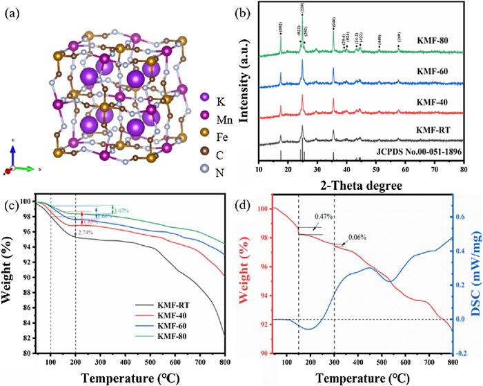
We synthesized a series of KMFs by a simple coprecipitation method. The KMFs have the open structure which schematic structure is shown in Fig. 1a. We can see that the three-dimensional network structure has large gap and the K locates at the interstitial position of the unit cell composed of Mn-NC-Fe. Their structures are carried out by X-ray diffraction (XRD), which results are shown in Fig. 1b. We successfully obtained the monoclinic KMFs [29], where the XRD patterns can be indexed to the (JCPDS No. 51-1896) except the peak at 32°. The KMF-RT exhibits the weakest diffraction intensity and the broadest diffraction peaks, indicating its smallest particle size. With the temperature increasing, the peaks become sharp and the intensities become strong. When the reaction temperature is raised to 80 ℃, the diffraction has the highest intensity and the peak located ~25° splits to three peaks. It means that the particle size increase and crystallinity of KMFs enhance with the increase of the reaction temperature.

|
Download:
|
| Fig. 1. (a) Structural illustration and (b) XRD patterns of KMFs. TGA curves of (c) all KMFs and segmentation curves of (d) KMF-40. | |
In order to understand the water content of the KMFs, thermal gravimetric analysis (TGA) was employed. As shown in Fig. 1c, with the reaction temperature increasing, the water content of the samples gradually decreases. There is only one step weight-loss below 200℃, which consists with the loss of the absorbed water and zeolitic water. Above 200℃, there is no obvious weight loss but an approximate platform, representing the elimination of the coordinated water lose step [27]. The reason for this phenomenon is due to the low coordinated water in the samples. Therefore, we performed TGA tests again, holding at 150 ℃ and 300 ℃ for 3 h to separately determine the content of two kinds of water (Fig. S1 in Supporting information). The XRD patterns of KMF-40 processing at 300 ℃ for 3 h is shown in Fig. S2 (Supporting information). It still matches well with KFM, indicating that the phase structure was not changed after heating at 300℃. We find that its coordinated water content is not monotonous increase with the temperature change, but has the lowest content at 40 ℃. The weight loss of KMF-40 at 150 ℃ and 300 ℃ is shown in the Fig. 1d, which represents the amount of zeolitic water and coordinated water, respectively. Then, the content of K, Mn and Fe were tested by AAS and ICP (Table S1 in Supporting information). Therefore, the real chemical formulas of the KMF-RT, KMF-40, KMF-60 and KMF-80 are K1.84Mn[Fe(CN)6]0.93·0.31 H2O, K1.99Mn[Fe(CN)6]0.98·0.13H2O, K1.97Mn[Fe(CN)6]0.97·0.38 H2O, K1.92Mn[Fe(CN)6]0.94·0.65 H2O, respectively. The KMF-40 has the least the vacancy of [Fe(CN)6] and water.
Although the KMFs are all of the same crystal structure, they have different morphologies, as showing in Fig. 2. The KMF-RT presents an irregular shape with minimal grain size and serious agglomeration with an average size of 25 nm. The KMF-40, KMF-60 and KMF-80 display the similar cubic morphologies but with different size. The average size of KMF-40, KMF-60 and KMF-80 is 50, 70 and 150 nm, respectively. KMF-40 exhibits the small size and without obvious agglomeration, which could short the ion transfer pathway, benefiting for the rate performance. The TEM images of KMF-40 are shown in Figs. 2e and f. The particles disperse well and the lattice fringes can be observed clearly, where the interplanar spacing is 0.505 nm, assigned to (002) crystal plane of KMF. The SAED patterns of KMF-40 simulated by Fig. 2f can be indexed to the (002) and (004) crystal planes.

|
Download:
|
| Fig. 2. SEM images of (a) KMF-RT, (b) KMF-40, (c) KMF-60 and (d) KMF-80. (e) TEM and (f) HRTEM (inset simulated SAED patterns) image of KMF-40. | |
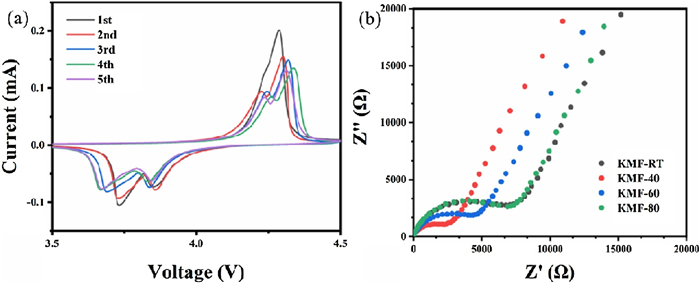
To understand the K+ ions storage properties in KMFs, cyclic voltammetry (CV), electrochemical impedance spectroscopy (EIS) and battery tests are employed. Fig. 3a shows the CV curves of KMF-40 electrode at a scan rate of 0.1 mV/s. The feature of initial CV curve presents a single oxidation peak and two reduction peaks. Only a single oxidation peak appears because the potentials of the two oxidation reactions are very close, merging to a large peak. However, two oxidation peaks can be observed in the subsequent cycles. Therefore, there are two pairs of redox peaks. The first pair of redox peaks located at about 4.26/3.87 V could be ascribed to the high-spin Mn3+/Mn2+ coordinated with nitrogen, and another pair of redox peaks located at about 4.2/3.73 V could be assigned to low-spin Fe3+/Fe2+ coordinated with carbon [30]. Except initial cycle, the subsequent curves are similar, indicating its good reversibility of the KMF-40. The CV curves of the other three samples are shown in Fig. S3 (Supporting information). The curves of KMF-RT and KMF-60 are similar as the KMF-40's. But only one oxidation peak can be observed in the first five circles of the CV curve of KMF-80. This may be due to the large particles and slow kinetic response, so the two-step redox reaction is not clearly distinguished. Then, we performed the EIS tests on the pristine half-cells after aging. The EIS results are shown in Fig. 3b, where the semicircle in the region of high frequency represents the charge transfer resistance (Rct) and the straight line in the region of low frequency is related to the bulk diffusion of K+ ions. It can be clearly seen that the Rct of KMF-40 is significantly smaller than other samples (the corresponding Rct values are listed at Table S2 in Supporting information), which is attributed to low coordinated water content (leading the few defects) and the continuous Fe-CN-Mn three-dimensional skeleton [4].

|
Download:
|
| Fig. 3. (a) Cyclic voltammetry (CV) curves of KMF-40 at 0.1 mV/s. (b) Electrochemical impedance spectra (EIS) of KMFs. | |
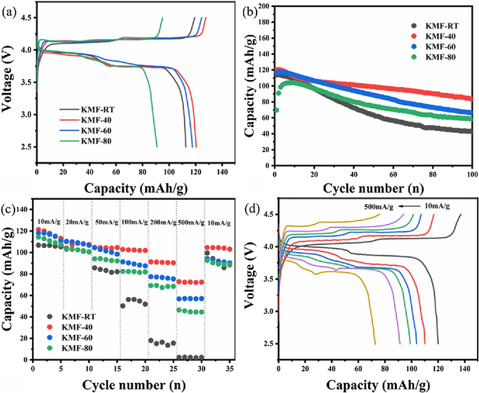
The electrochemical performances of these KMFs are tested in the half-cells configuration against metallic potassium, with an operation voltage window of 2.5–4.5 V (vs. K+/K). The galvanostatic charge/discharge profiles of the KMF cathodes were tested at a current density of 100 mA/g, shown in Fig. 4a. There are two nearby plateaus at around 4.2 V in the charging process, and two plateaus during the discharge process at around 3.9 V and 3.7 V, respectively, which are good consistent with the CV results. The KMF-40 electrode delivers a high reversible discharge capacity of 120.5 mAh/g, which should be attributed to its high K+-ion content and low Fe(CN)6 vacancies. The discharge capacities of KMF-RT, KMF-60 and KMF-80 are 112.5, 117.6 and 90.9 mAh/g, respectively. As shown in Fig. 4b, the cycling performance of KMFs performed at a current density of 100 mA/g. KMF-40 and KMF-60 exhibit better cycling stability and higher capacity than the other samples, where KMF-40 can deliver a capacity of 83.6 mAh/g after 100 cycles. The reaction between the coordinated water and the electrolyte will cause the collapse of the PW 3 D structure. Therefore, the excellent cycling performance of KMF-40 and KMF-60 is due to their low coordinated water. The KMF-80 has an obvious activation process because of its big particle size. The rate performance of the different KMF cathodes is shown in Figs. 4c and d at the current densities ranging from 10 mA/g (0.1 C) to 500 mA/g (5 C). Among them, the KMF-40 cathode shows the best rate performance, presenting the specific capacities of 120.5 mAh/g at 10 mA/g, and 73.2 mAh/g at 500 mA/g, retaining the 61% of its original capacity. When the current density goes back to 10 mA/g, the capacity can nearly recover, indicating the structure of PW can tolerant the fast insertion/desertion of K+ ions. The KMF-40 with high rate performance is considered to its low water content and its relative good crystal structure. Furthermore, it has smaller particle size without agglomeration among the samples, leading the shortest diffusion length during the K+ ions extraction/insertion processes.

|
Download:
|
| Fig. 4. (a) Charge-discharge curves of KMFs between 2.0 V and 4.5 V at a current density of 100 mA/g. (b) Cycling performance and (c) rate capability of KMFs. (d) Charge-discharge curves of KMF-40 from 10 mA/g to 500 mA/g. | |
In summary, a series of KMFs with different water contents were successfully synthesized by co-precipitation. The water contents can be tuned by reaction temperatures, and obtained sample at 40 ℃ presented low coordinated water content. Low coordinated water means KMFs has intact three-dimensional interconnected network structure and fewer defects. Moreover, low coordinated water suggests less side reaction with electrolyte during the cycle. As a result, KMF-40 delivers a good cycle life and good rate performance with 73.2 mAh/g at 500 mA/g. This work provides a modified co-precipitation method to synthesize PWs cathodes with low coordinated water content in nonaqueous KIBs, which exhibits the promising electrochemical performance.
Declaration of competing interestThe authors declare that they have no known competing financial interests or personal relationships that could have appeared to influence the work reported in this paper.
AcknowledgmentsThis research was funded by the National Natural Science Foundation of China (No. 51972258) and the Fundamental Research Funds for the Central Universities (WUT: No. 2019IVA007).
Appendix A. Supplementary dataSupplementary material related to this article can be found, in the online version, at doi:https://doi.org/10.1016/j.cclet.2021.01.025.
| [1] |
Y.S. Xu, S.Y. Duan, Y.G. Sun, et al., J. Mater. Chem. A 7 (2019) 4334-4352. DOI:10.1039/C8TA10953B |
| [2] |
N. Nitta, F. Wu, J.T. Lee, G. Yushin, Mater. Today 8 (2015) 252-264. |
| [3] |
Z. Yang, J. Zhang, M.C. Kintner-Meyer, et al., Chem. Rev. 111 (2011) 3577-3613. |
| [4] |
J. Qian, C. Wu, Y. Cao, et al., Adv. Energy. Mater. 8 (2018) 1702619. DOI:10.1002/aenm.201702619 |
| [5] |
H. Vikström, S. Davidsson, M. Höök, Appl. Energy 110 (2013) 252-266. DOI:10.1016/j.apenergy.2013.04.005 |
| [6] |
X. Wu, W. Deng, J. Qian, et al., J. Mater. Chem. A 1 (2013) 10130. DOI:10.1039/c3ta12036h |
| [7] |
C. Vaalma, D. Buchholz, S. Passerini, Curr. Opin. Electrochem. 9 (2018) 41-48. DOI:10.1016/j.coelec.2018.03.031 |
| [8] |
X. Zhang, D. Yang, X. Rui, Y. Yu, Curr. Opin. Electrochem. 18 (2019) 24-30. DOI:10.1016/j.coelec.2019.09.002 |
| [9] |
X. Wu, D.P. Leonard, J. Chem. Mater. 29 (2017) 5031-5042. DOI:10.1021/acs.chemmater.7b01764 |
| [10] |
D. Yang, C. Liu, X. Rui, Q. Yan, Nanoscale 11 (2019) 15402-15417. DOI:10.1039/C9NR05588F |
| [11] |
Y. Li, Q. Zhang, Y. Yuan, et al., Adv. Energy Mater. 10 (2020) 2070103. DOI:10.1002/aenm.202070103 |
| [12] |
Y. Cheng, Z. Yao, Q. Zhang, et al., Adv. Funct. Mater. 30 (2020) 2005417. DOI:10.1002/adfm.202005417 |
| [13] |
Y. Luo, B. Shen, B. Guo, et al., J. Phys. Chem. Solids 122 (2018) 31-35. DOI:10.1016/j.jpcs.2018.06.014 |
| [14] |
J.C. Pramudita, D. Sehrawat, D. Goonetilleke, N. Sharma, Adv. Energy Mater. 7 (2017) 1602911. DOI:10.1002/aenm.201602911 |
| [15] |
X. Bie, K. Kubota, T. Hosaka, K. Chihara, S. Komaba, J. Mater. Chem. A 5 (2017) 4325-4330. DOI:10.1039/C7TA00220C |
| [16] |
A.J. Naylor, M. Carboni, M. Valvo, R. Younesi, ACS Appl. Mater. Interfaces 11 (2019) 45636-45645. DOI:10.1021/acsami.9b15453 |
| [17] |
J. Chen, Y. Cheng, Q. Zhang, et al., Adv. Funct. Mater. (2020) 2007158. |
| [18] |
Z. Jian, W. Luo, X. Ji, J. Am. Chem. Soc. 137 (2015) 11566-11569. DOI:10.1021/jacs.5b06809 |
| [19] |
W. Ren, Z. Zhu, M. Qin, et al., Adv. Funct. Mater. 29 (2019) 1806405. DOI:10.1002/adfm.201806405 |
| [20] |
D. Su, A. McDonagh, S.Z. Qiao, G. Wang, Adv. Mater. 29 (2017) 1604007. DOI:10.1002/adma.201604007 |
| [21] |
D. Yang, J. Xu, X.Z. Liao, et al., Chem. Commun. 50 (2014) 13377-13380. DOI:10.1039/C4CC05830E |
| [22] |
X. Wu, Z. Jian, Z. Li, X. Ji, Electrochem. Commun. 77 (2017) 54-57. DOI:10.1016/j.elecom.2017.02.012 |
| [23] |
X. Jiang, T. Zhang, L. Yang, G. Li, J.Y. Lee, ChemElectroChem 4 (2017) 2237-2242. DOI:10.1002/celc.201700410 |
| [24] |
G. He, L.F. Nazar, ACS Energy Lett. 2 (2017) 1122-1127. DOI:10.1021/acsenergylett.7b00179 |
| [25] |
B. Huang, Y. Liu, Z. Lu, et al., ACS Sustain. Chem. Eng. 7 (2019) 16659-16667. DOI:10.1021/acssuschemeng.9b04012 |
| [26] |
Q. Xue, L. Li, Y. Huang, et al., ACS Appl. Mater. Interfaces 11 (2019) 22339-22345. DOI:10.1021/acsami.9b04579 |
| [27] |
W.J. Li, C. Han, G. Cheng, et al., Small 15 (2019) e1900470. DOI:10.1002/smll.201900470 |
| [28] |
C. Zhang, Y. Xu, M. Zhou, et al., Adv. Funct. Mater. 27 (2017) 1604307. |
| [29] |
M. Hu, J.S. Jiang, Mater. Res. Bull. 46 (2011) 702-707. DOI:10.1016/j.materresbull.2011.01.017 |
| [30] |
L. Xue, Y. Li, H. Gao, et al., J. Am. Chem. Soc. 139 (2017) 2164-2167. |