 2021, Vol. 32


b State Key Laboratory of Separation Membranes and Membrane Processes, School of Chemistry and Chemical Engineering, Tiangong University, Tianjin 300387, China
With the increasingly serious energy crisis and environmental pollution problems, photoelectrochemical (PEC) water splitting using sunlight to generate hydrogen has been regarded as a feasible way to achieve sustainable development [1]. Early-stage, numerous semiconductor materials, such as ZnO [2], BiVO4 [3], WO3 [4] and CdS [5] have been widely studied as photoanodes for PEC water splitting. Hematite (α-Fe2O3), a stable n-type semiconductor, stands out because of its nontoxicity, earth-abundance, and suitable band gap (2.1 eV) [6]. It absorbs about 40% of solar radiation, and the maximum theoretical photocurrent density can reach 12.6 mA/cm2 under AM 1.5 G illumination [7].
However, pure hematite photoanode suffers from poor conductivity, short hole diffusion distance (≈ 2 nm) [8], sluggish oxygen evolution kinetics [9], low carrier concentration, and severe recombination problems [10], which result in the PEC water splitting performance that can be achieved at present is still far below the theoretical limit. Various strategies have been proposed to solve these obstacles, including loading oxygen evolution cocatalysts (OECs) [11, 12], forming heterojunctions [13, 14], nanostructure engineering [15, 16] and surface passivation [17].
Element doping, an effective strategy to modify the charge transport properties of photoanodes bulk phase, could distort the crystal lattice, leading to polaron jumping or increasing the carrier concentration and conductivity of the α-Fe2O3 photoanodes [18]. Early-stage, metal doping has been widely used in hematite photoanodes, such as Ti4+ [19], Sn4+ [20], Zr4+ [21] and Cd2+ [22]. However, it is inevitable to introduce new energy levels between the valence band and the conduction band of hematite during doping, resulting in more severe charge recombination [23]. The introduction of nonmetallic elements into hematite can address the recombination issue of metal ion doping because the energy state caused by nonmetal dopants is generally above the conduction band of hematite [24]. As an electron donor, nonmetallic phosphorus (P) is a promising candidate for hematite doping, which has more valence electrons than many metal doping elements [25]. Moreover, compared with other dopant-O bonds, the P-O bond in hematite possesses a more covalent nature, which can effectively avoid the formation of deep electron capture sites in hematite [26].
The issue of charge separation in the bulk of hematite is solved by non-metallic doping. However, the sluggish surface reaction kinetics is still an important reason that limits the performance of α-Fe2O3 photoanode in PEC water oxidation. Compared with the generation speed of carriers in hematite, surface reactions commonly take place in a longer time range [27]. Up to now, it has been extensively studied by loading cocatalysts on its surface, which can reduce the overpotential and accelerate the reaction kinetics of the hematite surface, including Co-Pi [28], IrOx [29], NiOOH [30], Co3O4 [31], layered double hydroxides (LDHs) [32], etc. LDHs stand out because of their low cost, feasible moderation of interlayer object, and excellent stability, which have been regarded to be a promising OECs for PEC water oxidation [33-36].
Herein, we propose a co-activation strategy to solve the charge recombination and sluggish surface reaction of α-Fe2O3 through P doping and the loading of CoAl-LDHs OECs. The resulting CoAl-LDHs/P-Fe2O3 photoanodes shows an outstanding water oxidation photocurrent density of 1.56 mA/cm2 at 1.23 V (vs. RHE) under AM 1.5 G (100 mW/cm2) illumination, which is 2.6 times of pure α-Fe2O3. Besides, the onset potential is negatively shifted to 0.7 V (vs. RHE) and the surface charge separation efficiency is increased to 68.8% at 1.23 V (vs. RHE). Our research provides a feasible strategy to enhance the PEC performance of α-Fe2O3 photoanodes.
The α-Fe2O3 photoanodes were fabricated by a previously reported hydrothermal approach followed by annealing [37]. As shown in Fig. 1a, the α-Fe2O3 photoanodes show a nanorods structure on the fluorine-doped SnO2 (FTO) substrates, which is consistent with the transmission electron microscope (TEM) image (Fig. 2a). The high-resolution transmission electron microscope (HRTEM) image of α-Fe2O3 photoanodes (Fig. 2b) shows that the interval of the adjacent lattice plane is 0.25 nm, which is matched with the (110) plane of hematite. The crystallization of different photoanodes were investigated by X-ray diffraction (XRD) patterns (Fig. S2a in Supporting information). The diffraction peaks of α-Fe2O3 photoanodes at 36.1° and 64.4° are indexed as the (110) and (300) crystal plane of hematite (JCPDS card number 33-0664), respectively. Besides, the diffraction peak intensity of (110) crystal plane is higher than that of (300) crystal plane, indicating that the (110) crystal plane is mainly exposed in theα-Fe2O3 photoanodes, which is more conducive to the transfer of photogenerated charges [38]. As indicated by X-ray photoelectron spectroscopy (XPS), the binding energies of Fe 2p1/2 and Fe 2p3/2 for α-Fe2O3 are 723.5 eV and 709.6 eV respectively (Fig. S3a in Supporting information), consistent with literature reports [39]. In Fig. S3b (Supporting information), the O 1s spectrum of α-Fe2O3 can be decomposed into three peaks. The peak at 529.4 eV is characteristic of the O2− species (designated as Fe-O) in the Fe2O3, while the other two peaks are attributed to surface labile oxygen, such as chemisorbed active O, including O22− and O− (531.2 eV, designated as O*) and adsorbed molecular water (532.7 eV, designated as Ow) [40, 41]. Scanning electron microscopy (SEM), TEM, HRTEM, XRD and XPS results indicate the successful preparation of the α-Fe2O3 photoanodes.

|
Download:
|
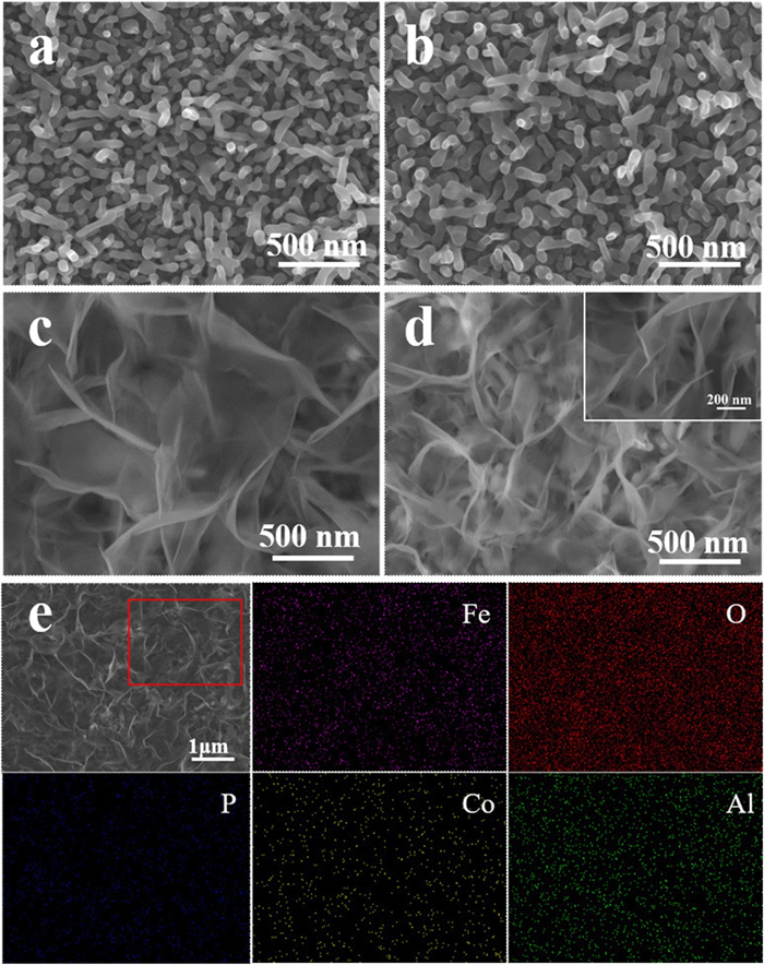
| Fig. 1. SEM images of (a) α-Fe2O3 NRs photoanodes, (b) P-Fe2O3 NRs photoanodes, (c) CoAl-LDHs/Fe2O3 photoanodes and (d) CoAl-LDHs/P-Fe2O3 photoanodes. (e) SEM-EDX elemental mapping images of Fe, O, P, Co, Al in CoAl-LDHs/P-Fe2O3 photoanodes. | |

|
Download:
|
| Fig. 2. TEM images of (a) α-Fe2O3 NRs photoanodes and (c) CoAl-LDHs/P-Fe2O3 photoanodes. HRTEM images of (b) α-Fe2O3 NRs photoanodes and (d) CoAl-LDHs/P-Fe2O3 photoanodes. | |
The morphology of P-Fe2O3 (Fig. 1b) obtained by the annealing process is unchanged compared to the α-Fe2O3 photoanodes. As shown in Fig. S2a, the XRD pattern of the P-Fe2O3 photoanodes is the same as the α-Fe2O3 photoanodes, which implies that P doping does not affect the crystal structure of α-Fe2O3. In Fig. S3a, it is observed that the Fe 2p spectra of P-Fe2O3 and CoAl-LDHs/P-Fe2O3 are almost the same for the α-Fe2O3 photoanodes, indicating that the P doping and the loading of CoAl-LDHs OECs do not affect the chemical states of Fe atoms. As shown in Fig. S3c (Supporting information), it can be obviously seen that the peak at approximately 132.4 eV can be indexed to P5+ specie [42]. The Fe 2p and P 2p signals of CoAl-LDHs/P-Fe2O3 samples are close to that of FePO4, which indicates a strong interaction between the Fe and P in photoanodes [25]. SEM, XRD and XPS results show that the P-Fe2O3 photoanodes were successfully prepared.
As shown in Fig. 1d, when CoAl-LDHs were loaded onto the P-Fe2O3 photoanodes, their surface morphology demonstrates a significant change with nanosheets clearly shown on the surface, which is the same as CoAl-LDHs/Fe2O3 photoanodes (Fig. 1c). Energy-dispersive X-ray spectrum (EDX) mappings (Fig. 1e) of Fe, O, P, Co and Al illustrate that each element distributes homogeneously in the nano-arrays. The TEM image (Fig. 2c) reveals CoAl-LDHs OECs compactly coated on the surface of α-Fe2O3, which would facilitate the separation and transfer of photogenerated carriers in bulk α-Fe2O3. The CoAl-LDHs/P-Fe2O3 photoanodes displays a lattice spacing of 0.25 nm (Fig. 2d), indicating that the crystal structure of hematite remains unchanged after introducing phosphorus dopant into the hematite lattice. In Fig. S2a, the XRD pattern of the CoAl-LDHs/P-Fe2O3 photoanodes is the same as the α-Fe2O3 photoanodes, which implies that P doping and loading of CoAl-LDHs OECs do not affect the crystal structure of α-Fe2O3. These analysis results are consistent with HRTEM. The ultraviolet-visible (UV–vis) diffuse reflectance spectra of different photoanodes (Fig. S2b in Supporting information) reveal that P doping and the loading of CoAl-LDHs could only slightly enhance the light absorption ability of α-Fe2O3 photoanodes, indicating that the main factors affecting the PEC performance of hematite are charge separation and surface reaction kinetics [43]. As indicated by Fig. S3b, the O* peak becomes strong, which can be ascribed to the OH− groups in CoAl-LDHs, indicating that the CoAl-LDHs OECs cover the surface of P-Fe2O3 photoanodes. The above results show the successful preparation of the CoAl-LDHs/P-Fe2O3 photoanodes. The Co 2p core-level spectra are utilized to investigate the valences of Co species in the CoAl-LDHs/P-Fe2O3 photoanodes (Fig. S3d in Supporting information). The Co 2p core lines are divided into two peaks of Co 2p1/2 (797.2 eV) and Co 2p3/2 (781.3 eV) accompanied by two satellite bands at 803.4 eV and 786.1 eV respectively, indicating that the Co cation exists as high-spin Co2+ in CoAl-LDHs/P-Fe2O3 photoanodes [44].
The PEC water oxidation activities of different photoanodes were evaluated by measuring the photocurrent–voltage (J–V) curves in 1 mol/L NaOH (pH 13.6) under AM 1.5 G simulated sunlight (100 mW/cm2). From the J–V curves in Fig. 3a, we can observe that the pure α-Fe2O3 shows a low photocurrent density of 0.6 mA/cm2 at 1.23 V (vs. RHE). When the α-Fe2O3 photoanodes are modified with phosphorus doping, the P-Fe2O3 photoanodes display a much higher photocurrent density than that of the α-Fe2O3 photoanodes due to the carrier density (Nd) of P-Fe2O3 photoanodes (1.37×1020 cm−3) increased by 2.89 times compared with pure hematite (Fig. 3b). Moreover, CoAl-LDHs/Fe2O3 photoanodes demonstrate an enhanced photocurrent density compared to the α-Fe2O3 photoanodes, while a pure CoAl-LDHs photoanode in 1 mol/L NaOH electrolyte shows a photocurrent and dark current densities of almost zero at 1.23 V (vs. RHE), which indicates that the CoAl-LDHs OECs accelerate the water oxidation kinetics rather than photosensitivity (Fig. S10 in Supporting information). When P doping and loading the CoAl-LDHs cocatalysts for hematite at the same time, the photoanodes exhibit a photocurrent density of 1.56 mA/cm2 at 1.23 V (vs. RHE), which is 1.6 times higher than that of pure α-Fe2O3. Besides, the onset potential shows a cathodic shift of 100 mV, indicating a lower overpotential for water oxidation. The maximum applied bias photon-to-current efficiency (ABPE) of the CoAl-LDHs/P-Fe2O3 photoanodes achieves 0.20% at 1.0 V (vs. RHE), which is 3.84 times that of the bare α-Fe2O3 photoanodes (Fig. 3c).

|
Download:
|
| Fig. 3. (a) J–V curves of different photoanodes measured with 1 mol/L NaOH (pH 13.6) under AM 1.5 G simulated sunlight (100 mW/cm2). (b) Mott-Schottky plots of different samples measured in 1 mol/L NaOH solution in dark (1 kHz). (c) ABPE of different photoanodes. (d) EIS Nyquist plots of different photoanodes. The inset reveals equivalent circuit for different photoanodes in the light. | |
Electrochemical impedance spectroscopy (EIS) measurement was performed to investigate the charge transport properties of the photoanodes under AM 1.5 G illumination (Fig. 3d) [45]. According to the EIS results, the semidiameter of the semicircle of P-Fe2O3 and CoAl-LDHs/Fe2O3 photoanodes are dramatically reduced compared to pure α-Fe2O3, indicating that P doping could reduce the surface charge trapping of hematite, and CoAl-LDHs cocatalysts can effectively facilitate the transport of holes into the electrolyte for water oxidation. Moreover, compared to other photoanodes, the semidiameter of the semicircle of CoAl-LDHs/P-Fe2O3 is the smallest, further confirming that the photoanodes have the best charge transport performance, which is consistent with the PEC results.
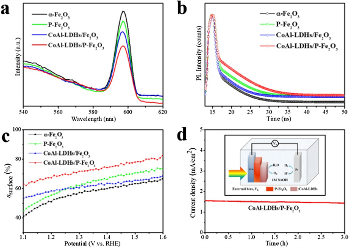
Photoluminescence (PL) spectra and time-resolved photoluminescence (TRPL) emission decay spectra can be used to evaluate the recombination degree of photo-generated carriers in semiconductors in photocatalysis [3]. A long carrier lifetime and low fluorescence intensity mean efficient charge separation for photoanodes. In Fig. 4a, all samples have the same emission peak at 597 nm, and the fluorescence intensity of α-Fe2O3 is the strongest, indicating that pure hematite suffers from severe carrier recombination. In contrast, the fluorescence intensity of P-Fe2O3 and CoAl-LDHs/Fe2O3 are reduced, and the average fluorescence lifetimes both increase (Fig. 4b), indicating that P doping and the loading of CoAl-LDHs OECs can inhibit the recombination of hematite photo-generated carriers. Among them, the average fluorescence lifetimes of the CoAl-LDHs/P-Fe2O3 photoanode is 3.136 ns, 1.25 times higher than that of α-Fe2O3, exhibiting the most excellent carrier separation efficiency, which is consistent with the PEC results. This result is further confirmed by the surface charge separation efficiencies of different photoanodes (Fig. 4c). A high surface charge separation efficiency (68.8%) is obtained for CoAl-LDHs/P-Fe2O3 photoanodes compared with that of the pure α-Fe2O3 (53.7%) at 1.23 V (vs. RHE). The stability of the CoAl-LDHs/P-Fe2O3 photoanode was tested by chronoamperometry (Fig. 4d). After continuous exposure to AM 1.5 G illumination for 3 h, there is no obvious difference in the recorded photocurrent, indicating its excellent photoelectric stability.

|
Download:
|
| Fig. 4. (a) PL spectra of different samples. (b) TRPL emission decay spectra of different photoanodes. (c) The surface charge separation efficiencies of different photoanodes. (d) I–t curves for CoAl-LDHs/P-Fe2O3 photoanodes measured at 1.23 V (vs. RHE) in 1 M NaOH solution under AM 1.5 G illumination (100 mW/cm2). The inset shows the schematic of PEC cell for water splitting. | |
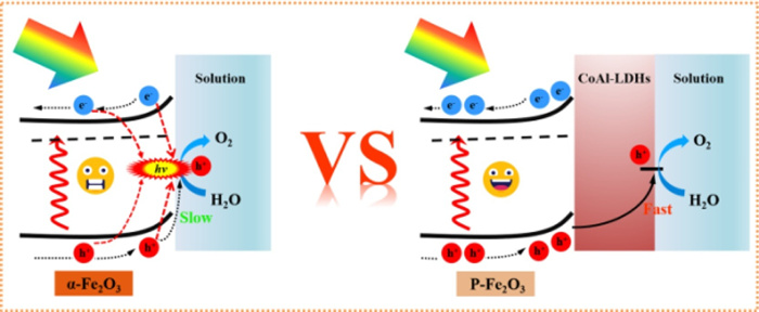
Based on the above analysis, Scheme 1 is a schematic diagram of the photogenerated electron-hole pairs separation and transport process of the CoAl-LDHs/P-Fe2O3 composite photoanodes. Hematite suffers from severe surface charge recombination and sluggish water oxidation kinetics, which results in inferior PEC performance. Phosphorus anion as a donor dopant significantly increases the carrier density of hematite and reduces the resistance to charge transfer. Besides, the electronic structure change caused by P doping could remove part of the hematite surface trapping sites and reduce the surface charge capture. The CoAl-LDHs OECs can effectively improve the kinetics of water oxidation on the surface of the hematite photoanode, and promote the transport of holes into the electrolyte for water oxidation. Moreover, P anion doping and the loading of CoAl-LDHs cocatalysts can both inhibit surface charge recombination and facilitate surface charge separation. Through the conversion of Co cations to high valence states during the water oxidation process, the injection efficiency of photogenerated holes could be obviously enhanced. Owing to the successive modification of P doping and CoAl-LDHs OECs, the CoAl-LDHs/P-Fe2O3 photoanodes exhibit outstanding PEC water oxidation performance.

|
Download:
|
| Scheme 1. Schematic diagram of the photogenerated electron-hole pairs separation and transport process of the photoanodes. | |
In summary, we designed a co-activation strategy to solve the charge recombination and sluggish surface reaction of α-Fe2O3 through P doping and the loading of CoAl-LDHs OECs. Among them, P anion doping significantly increases the carrier density of hematite and reduces the resistance of charge transfer. The CoAl-LDHs OECs not only accelerates the water oxidation kinetics of hematite but also effectively improves the injection efficiency of photogenerated holes through the conversion of cobalt ions. Besides, the P anion doping and the loading of the CoAl-LDHs OECs are both facilitated to the separation of the surface charge of the hematite, which is more effective for PEC water oxidation. As a result, the CoAl-LDHs/P-Fe2O3 photoanodes exhibits an outstanding photocurrent density of 1.56 mA/cm2 at 1.23 V (vs. RHE), which is 2.6 times of pure α-Fe2O3. Besides, the onset potential is negatively shifted from 0.8 V to 0.7 V (vs. RHE) and the Nd of CoAl-LDHs/P-Fe2O3 photoanodes obtained from Mott-Schottky results is 1.84×1020 cm−3. The ABPE achieves 0.20% at 1.0 V (vs. RHE), which is 3.84 times that of the bare α-Fe2O3 photoanodes, and the surface charge separation efficiency is increased to 68.8% at 1.23 V (vs. RHE). Our research demonstrates that co-activation of anion doping and cocatalysts is a favorable strategy to improve the PEC performance of hematite.
Declaration of competing interestThe authors report no declarations of interest.
AcknowledgmentsThis work was supported by the National Natural Science Foundation of China (No. 21575115); the Program for Chang Jiang Scholars and Innovative Research Team, Ministry of Education, China (No. IRT-16R61).
Appendix A. Supplementary dataSupplementary material related to this article can be found, in the online version, at doi:https://doi.org/10.1016/j.cclet.2021.01.003.
| [1] |
D.K. Lee, K.S. Choi, Nat. Energy 3 (2018) 53-60. DOI:10.1038/s41560-017-0057-0 |
| [2] |
H.P. Ma, J.H. Yang, J.J. Tao, et al., Nano Energy 66 (2019) 104089. DOI:10.1016/j.nanoen.2019.104089 |
| [3] |
X. Ning, B. Lu, Z. Zhang, et al., Angew. Chem. Int. Ed. 58 (2019) 16800-16805. DOI:10.1002/anie.201908833 |
| [4] |
S. Corby, L. Francas, S. Selim, et al., J. Am. Chem. Soc. 140 (2018) 16168-16177. DOI:10.1021/jacs.8b08852 |
| [5] |
G. Ai, H. Li, S. Liu, R. Mo, J. Zhong, Adv. Funct. Mater. 25 (2015) 5706-5713. DOI:10.1002/adfm.201502461 |
| [6] |
C.C. Li, Z.B. Luo, T. Wang, J.L. Gong, Adv. Mater. 30 (2018) 1707502. DOI:10.1002/adma.201707502 |
| [7] |
Y.J. Lin, S. Zhou, S.W. Sheehan, D.W. Wang, J. Am. Chem. Soc. 133 (2011) 2398-2401. DOI:10.1021/ja110741z |
| [8] |
S.R. Pendlebury, X. Wang, F. Le Formal, et al., J. Am. Chem. Soc. 136 (2014) 9854-9857. DOI:10.1021/ja504473e |
| [9] |
S. Kment, F. Riboni, S. Pausova, et al., Chem. Soc. Rev. 46 (2017) 3716-3769. DOI:10.1039/c6cs00015k |
| [10] |
F. Le Formal, S.R. Pendlebury, M. Cornuz, et al., J. Am. Chem. Soc. 136 (2014) 2564-2574. DOI:10.1021/ja412058x |
| [11] |
B.B. Zhang, L. Wang, Y.J. Zhang, Y. Ding, Y.P. Bi, Angew. Chem. Int. Ed. 57 (2018) 2248-2252. DOI:10.1002/anie.201712499 |
| [12] |
M. Wang, M. Wang, Y. Fu, S. Shen, Chin. Chem. Lett. 28 (2017) 2207-2211. DOI:10.1016/j.cclet.2017.11.037 |
| [13] |
S.S. Yi, B.R. Wulan, J.M. Yan, Q. Jiang, Adv. Funct. Mater. 29 (2019) 1801902. DOI:10.1002/adfm.201801902 |
| [14] |
Y. Chao, P. Zhou, N. Li, et al., Adv. Mater. 31 (2019) 1807226. DOI:10.1002/adma.201807226 |
| [15] |
P. Peerakiatkhajohn, J.H. Yun, H.J. Chen, et al., Adv. Mater. 28 (2016) 6405-6410. DOI:10.1002/adma.201601525 |
| [16] |
L. Cai, Y.C. Du, X.J. Guan, S.H. Shen, Chin. Chem. Lett. 30 (2019) 2363-2367. DOI:10.1016/j.cclet.2019.07.020 |
| [17] |
J.W. Jang, C. Du, Y.F. Ye, et al., Nat. Commun. 6 (2015) 7447. DOI:10.1038/ncomms8447 |
| [18] |
C.X. Kronawitter, I. Zegkinoglou, S.H. Shen, et al., Energy Environ. Sci. 7 (2014) 3100-3121. DOI:10.1039/C4EE01066C |
| [19] |
R. Franking, L.S. Li, M.A. Lukowski, et al., Energy Environ. Sci. 6 (2013) 500-512. DOI:10.1039/C2EE23837C |
| [20] |
M.Y. Li, Y. Yang, Y.C. Ling, et al., Nano Lett. 17 (2017) 2490-2495. DOI:10.1021/acs.nanolett.7b00184 |
| [21] |
T.T. Jiao, C. Lu, D. Zhang, et al., Appl. Catal. B: Environ. 269 (2020) 118768. DOI:10.1016/j.apcatb.2020.118768 |
| [22] |
A. Bak, W. Choi, H. Park, Appl. Catal. B-Environ. 110 (2011) 207-215. DOI:10.1016/j.apcatb.2011.09.002 |
| [23] |
P.L. Liao, M.C. Toroker, E.A. Carter, Nano Lett. 11 (2011) 1775-1781. DOI:10.1021/nl200356n |
| [24] |
H.J. Ahn, K.Y. Yoon, M.J. Kwak, J. Park, J.H. Jang, ACS Catal. 8 (2018) 11932-11939. DOI:10.1021/acscatal.8b03184 |
| [25] |
Z.B. Luo, C.C. Li, S.S. Liu, T. Wang, J.L. Gong, Chem. Sci. 8 (2017) 91-100. DOI:10.1039/C6SC03707K |
| [26] |
Y. Zhang, S. Jiang, W. Song, et al., Energy Environ. Sci. 8 (2015) 1231-1236. DOI:10.1039/C4EE03803G |
| [27] |
A. Kubacka, M. Fernandez Garcia, G. Colon, Chem. Rev. 112 (2012) 1555-1614. DOI:10.1021/cr100454n |
| [28] |
D. Chen, Z.F. Liu, Z.G. Guo, M.N. Ruan, W.G. Yan, ChemSusChem 12 (2019) 3286-3295. DOI:10.1002/cssc.201901331 |
| [29] |
W. Li, D. He, S.W. Sheehan, et al., Energy Environ. Sci. 9 (2016) 1794-1802. DOI:10.1039/C5EE03871E |
| [30] |
F. Li, J. Li, L.L. Gao, et al., J. Mater. Chem. A 6 (2018) 23478-23485. DOI:10.1039/c8ta07832g |
| [31] |
C.M. Li, Z.H. Chen, W.Y. Yuan, Q.H. Xu, C.M. Li, Nanoscale 11 (2019) 1111-1122. DOI:10.1039/c8nr07041e |
| [32] |
G. Wang, B.Y. Wang, C.H. Su, et al., J. Catal. 359 (2018) 287-295. DOI:10.1016/j.jcat.2018.01.011 |
| [33] |
R.F. Chong, B.Y. Wang, C.H. Su, et al., J. Mater. Chem. A 5 (2017) 8583-8590. DOI:10.1039/C7TA01586K |
| [34] |
S.L. Bai, H.M. Chu, X. Xiang, et al., Chem. Eng. J. 350 (2018) 148-156. DOI:10.1016/j.cej.2018.05.109 |
| [35] |
C.L. Wang, X.F. Long, S. Wei, et al., ACS Appl. Mater. Interfaces 11 (2019) 29799-29806. DOI:10.1021/acsami.9b07417 |
| [36] |
G. Chen, R. Gao, Y. Zhao, et al., Adv. Mater. 30 (2018) 1704663. DOI:10.1002/adma.201704663 |
| [37] |
C. Li, A. Li, Z. Luo, et al., Angew. Chem. Int. Ed. 56 (2017) 4150-4155. DOI:10.1002/anie.201611330 |
| [38] |
A. Kay, I. Cesar, M. Gratzel, J. Am. Chem. Soc. 128 (2006) 15714-15721. DOI:10.1021/ja064380l |
| [39] |
J.F. Zhang, R. Garcia-Rodriguez, P. Cameron, S. Eslava, Energy Environ. Sci. 11 (2018) 2972-2984. DOI:10.1039/c8ee01346b |
| [40] |
T. Boningari, P.R. Ettireddy, A. Somogyvari, et al., J. Catal. 325 (2015) 145-155. DOI:10.1016/j.jcat.2015.03.002 |
| [41] |
Y. Du, Q. Wang, X. Liang, et al., J. Catal. 331 (2015) 154-161. DOI:10.1016/j.jcat.2015.08.013 |
| [42] |
Q. Rui, L. Wang, Y.J. Zhang, et al., J. Mater. Chem. A 6 (2018) 7021-7026. DOI:10.1039/C8TA00556G |
| [43] |
X. Ning, P. Du, Z. Han, J. Chen, X. Lu, Angew. Chem. Int. Ed. 59 (2020) 13014. |
| [44] |
R.Z. Ma, J.B. Liang, K. Takada, T. Sasaki, J. Am. Chem. Soc. 133 (2011) 613-620. DOI:10.1021/ja1087216 |
| [45] |
Y.C. Zhang, S.Q. Jiang, W.J. Song, et al., Energy Environ. Sci. 8 (2015) 1231-1236. DOI:10.1039/C4EE03803G |