 2021, Vol. 32


b Shaanxi Key Laboratory of Optoelectronic Functional Materials and Devices, School of Materials Science and Chemical Engineering, Xi'an Technological University, Xi'an 710021, China;
c Institute of Environmental and Energy Catalysis, School of Materials Science and Chemical Engineering, Xi'an Technological University, Xi'an 710021, China;
d College of Resources and Environmental Engineering, Tianshui Normal University, Tianshui 741001, China
Ammonia borane (NH3BH3, AB) has recently been considered as a promising candidate for chemical hydrogen storage application due to its low molecular weight and high hydrogen content of 19.6 wt% [1, 2]. Compared with other hydrides, it is a better way to release H atom in AB to generate H2 [3-8]. In previous studies, we have obtained a variety of H2 preparation processes and high-performance catalytic methods [9-12]. Of these, nano-particles (NPs) of noble metals (such as Pt, Ru, Pd) or their alloys are the most active catalysts toward AB hydrolysis [13-16]. However, the high cost and limited availability of these metals have hindered the widespread application of noble metal NPs. Thus, the development of alternative efficient and economical catalysts for rapid H2 release is of great importance but remains a great challenge [17-19].
Thus, some low-cost catalysts have been revealed, such as solid acid [20] and transition metals core-shell catalysts [21, 22]. Among them, transition metals such as Fe, Co, Ni, W [23-28] have been paid more and more attention. Yan et al. [23] reported that in situ prepared Fe NPs possessed better catalytic property for the hydrolysis of ammonia borane, comparing with situ synthesized Fe sample. However, the catalytic activity of Fe NPs for the dehydrogenation of AB is still pretty low. Studies by Qiu et al. [29] show that the catalytic activity of the FeCo binary nanocluster structure is much higher than that of pure Fe NPs. This provides a new idea for the study of binary transition metal nanocluster structure catalysts. In contrast to the monometallic and alloy catalyst, the in situ generated bimetallic core-shell NPs have exhibited synergistic and superior catalytic activity for hydrolytic dehydrogenation of AB. So, considering both the catalytic performance and the catalyst cost, Fe@Co core-shell nanoparticles should be promising. Cui et al. [30] synthesized and reported NiFeNPs as the catalyst of AB hydrolysis reaction. With the addition of Fe, through the synergistic effect of FeNi, the charge transfer is promoted. Samely, the TOF of the AB hydrolysis reaction change from 4.41 min−1 to 23.25 min−1 at 298 K, and the activation barrier reached 38.24 kJ/mol. Chen et al. [31] first built and studied Pt-WO3 dual-active-sites to boost hydrogen generation from AB. With the addition of W, the activation barrier of the AB hydrolysis reaction reached 27.8 kJ/mol. The research of Zhou et al. [32] shows that Ru-Fe nanoalloys supported on N-doped carbon can efficiently catalyze the hydrolysis of AB to H2. By adjusting the atomic ratio of Ru and Fe, the reaction activation barrier reaches 33.7 kJ/mol, and the reaction rate is 424 mol H2 mol Ru−1 min−1, which is faster in Ru-based catalytic materials. Yang et al. [33] studied Co-based non-noble metal (Fe, Ni, Cu and Zn) nano-alloy structure to catalyze the hydrolysis of AB to produce H2 through experiments. The study found that CoCu and CoFe nano-alloy structure catalysts have better properties. Due to the good catalytic activity and cheaper cost, CoFe nanostructures have become an ideal catalyst material for AB hydrolysis. Those all shows that transition metals Fe and Co are ideal catalyst materials for AB hydrolysis. However, experimental research often focuses on the reaction rate and H2produce ratio of the catalytic reaction, and the research on the catalytic reaction path and reaction mechanism is still lacked, and it is difficult to design a catalyst material structure model from a theoretical perspective.
In this paper, we have constructed the Fe22@Co58 core-shell structure as a catalyst for the hydrolysis reaction of AB. The role of H2O molecules in the hydrolysis process was discussed, and the reaction processes and energy diagram of several different reaction paths were obtained and compared. Our calculations have important reference value for the study of the role of H2O molecules in the Fe22@Co58 core-shell structure catalyzed hydrolysis reaction of ammonia borane.
The surface charge distribution of the core-shell structure and the catalytic reaction path are calculated using the First-principles calculation method based on density functional theory (DFT) [34]. And the calculations were performed by using Vienna ab initio simulation package (VASP) [35, 36]. The projector augmented wave potentials are used for electronion interactions, and the exchange-correlation effect was treated with the generalized gradient approximation (GGA) proposed by Perdew-Burke-Ernzerhof (PBE) [37, 38]. The Van der Waals interaction is considered in the calculation process by using DFT+D3 [39, 40]. A plane wave basis set with cut-off energy 400 eV is used and spin-polarization is taken into account. An ionic and electronic relaxation converged within the error of 1×10⁻³ eV/atom and the convergence precision is set to force less than 0.01 eV/Å. Only the gamma k-points grid was used to describe the Brillouin zone for geometric optimization and self-consistent calculations [41]. The energy barriers have been calculated by the climbing image nudged elastic band (CI-NEB) method [42-45]. For CI-NEB calculation, cut-off energy set to 300 eV and the break condition for the ionic relaxation loop is -0.1 eV/Å. A canonical ensemble is simulated using the algorithm of Nose. We carried out simulations at constant temperatures (NVT conditions) at 300 K for stability test.
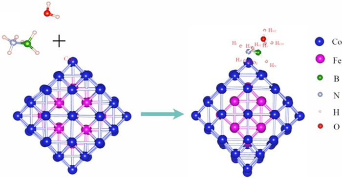
Experimental studies have shown that the interaction between Fe-Co atoms can promote structural stability. Fe@Co core-shell structure, molar ration of Fe to Co is 1:2 as determined by using XPS analysis, is a stable structure [46], and could catalyze sodium borohydride to produce H2 at room temperature (303 K). Therefore, we build the structural model as shown in Fig. 1. The charge distribution of AB and H2O molecule co-adsorption structure is shown in Table S1 (Supporting information).The outer Co atom layer wraps the core of Fe cluster, denoted as Fe22@Co58.

|
Download:
|
| Fig. 1. Fe22@Co58 core-shell structure (Hi, Hii and Hiii represent the H atom bond to the N atom. Hiv, Hv and Hvi represent the H atom bond to the B atom. Hvii and Hviii represents the H atom in H2O). | |
The core-shell binding energy (Ecs) is calculated to evaluate the stability of the core-shell structure. The calculation formula is as follows:

|
(1) |
Where, E(Fe22@Co58), E(Fe22), E(Co58) represent the total energy of core-shell structure, core structure, and shell structure, respectively.
The calculation results show that Ecs = 0.94 eV, which is a larger value compared with the stable structures such as Pt55, Ni13@Pt42, Co13@Pt42 and Fe13@Pt42 [47-50]. Furthermore, we performed the first-principles molecular dynamics calculations. The calculation results show that the structure can better maintain the original appearance at 300 K (Fig. S1 in Supporting information).
The strength of AB adsorption will affect the process of catalytic reaction. Therefore, the AB adsorption energy is calculated by the following formula:

|
(2) |
Where E(Fe22@Co58+AB), E(Fe22@Co58) and E(AB) represent the total energy of adsorbed structure, core structure, and AB molecule, respectively.
The calculation shows that Ea(AB) = -1.52 eV, indicating that AB has a strong adsorption interaction with the surface of core-shell structure. Similarly, the adsorption energy of the co-adsorption structure of AB and H2O is calculated using the following formula:
|
(3) |
Where, E(Fe22@Co58+AB+H2O), E(Fe22@Co58) and E(AB+H2O) represent the total energy of co-adsorbed structure, core structure, and AB+H2O molecule, respectively. The calculation results show that Ea(AB+H2O) = -1.88 eV, which indicates that H2O will strengthen the adsorption of AB, which is beneficial to the further activation of AB molecules.
Firstly, we study the AB dehydrogenation reaction with and without the effect of H2O molecules (route Ⅰ). During the reaction, all hydridic hydrogen of −BH3 group and protic hydrogen of -NH3 group are dropped and generate 3H2 molecules and H2O molecules does not dissociate during the dehydrogenation process (the reaction process is shown in Fig. S2 in Supporting information).
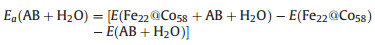
The energy change of the AB dehydrogenation process (with and without the effect of H2O molecules) is ploted in Fig. 2a. From Figs. S3, S4 (Supporting information) and Fig. 2a, it can be seen that if the H2O molecule does not dissociate, it hardly affect the energy change of the reaction process (1 mol AB generates 3 mol H2, and all H atoms come from AB molecules) and only the B-H and N-H bonds are broken during the whole reaction process. When the first H2 molecule generated, the overall reaction process is exothermic and spontaneous. However, when the second H2 molecule generated, the reaction becomes an endothermic process, and the heat absorption is about 1.0 eV. The reaction RDS appears between structure 8 and 10 and the barrier value is 1.2 eV. In this way, when the second H2 molecule is formed, the system absorbs heat reach to 2.2 eV, which is not conducive to the reaction at room temperature. Meanwhile, from the formation of the second H2 molecule to the third H2 molecule, the system continues to absorb heat about 1.0 eV.

|
Download:
|
| Fig. 2. Route Ⅰ: (a) Energy change (ΔE) on the path 1 (with the effect of H2O molecule) and path 3 (without the effect of H2O molecule). (b) The effect of *OH on reaction step 6–8. | |
Observed Fig. 2b, it can be found that through the adsorption of *OH, H atoms (Hii and Hiv) move from the hollow position of Co-Co-Co to the top position of Fe. Since Fe atoms are located in the core of the structure, the adsorption effect of Fe atoms on H atoms will be much weaker. The chemical bond changes from 1.72 Å (1.71 Å) of H-Co to 1.83 Å (1.90 Å) of H-Fe. In this way, it is beneficial to migrate H atoms and form the H2 molecules. It can be found from Fig. 2 that the reaction heat absorption of isolated hydrogen atoms to form H2 are relatively large, and the presence of *OH in the solution will greatly reduce heat absorption and promote the formation of H2 molecules. This effect is accomplished by changing the strength of the H-Co bond and promoting the migration of isolated H atoms. Combined with the purple part of the graph in Fig. 2a, it can be found that the addition of *OH is beneficial to the process of isolated H atom combining to generate H2for each part of path, which can significantly reduce the heat absorbed of the reaction.
For the AB dehydrogenation reaction, involving H2O molecules (route Ⅱ), after breaking the B-H bond or N-H bond, one H2O molecules dissociate and product *OH and isolated H atoms. In this way, two isolated H atoms combine to form H2 (Fig. 3). In Fig. 3a, the reaction barrier for breaking the B-H bond (step 1–3) is 0.57 eV, and the reaction endothermic is 0.30 eV, while in Fig. 3b, the breaking N-H bond (step 1–3) barrier is 0.59 eV and the reaction exothermic is 0.70 eV. This process has the same energy barrier (0.55 eV and 0.57 eV) as the process of breaking the B-H bond and breaking the N-H bond in Fig. 2 (step 2–4 and step 4–6). Subsequently, the process of dissociation of H2O molecules is an exothermic reaction and the process of forming H2 from H atoms is an endothermic reaction. Therefore, the overall reaction of B-H bond cleavage is an endothermic reaction and the overall reaction of N-H bond cleavage is an exothermic reaction.

|
Download:
|
| Fig. 3. Route Ⅱ: (a) The path 5 (broken B-H bond). (b) Path 6 (broken N-H bond) reaction process and energy changes. | |
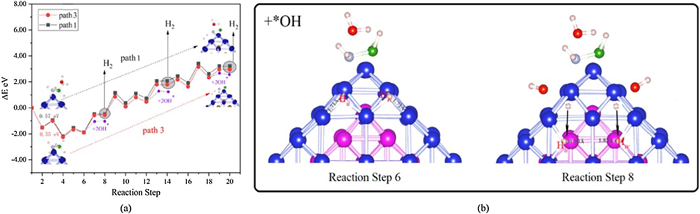
Now, we consider the case where the B-N bond is broken (route Ⅲ). As shown in Fig. 4a, after the B-N bond is broken, H2O molecules inserted between B and N. At this time, one H atom of the H2O molecule is captured by N. It can be found that both the B-H bond and the N-H bond become longer at this time. Among them, the N-H bond length changes from 1.05 Å to 1.11 Å, and the B-H bond changes from 1.34 Å to 1.58 Å. It shows that both the B-H bond and the N-H bond are weakened. As shown in Figs. 4b and c, after the B-N bond is broken, Hvii atoms are captured by N atoms, and the Hvii-O bond can be greatly weakened at this time.

|
Download:
|
| Fig. 4. (a) The bond length, (b) charge density diagram, (c) -COHP and (d) atoms charge change of the process of B-N bond breaking (the atom labels in the figure are from Fig. 1). | |
Seen from Fig. 4d, it can be found that electrons are transferred from N atom to H atom, which weakens the N-H bond, so the N-H bond is broken first. The charge transfer between the B-H bonds is weak, so it is not weakened too much. At this time, the O-H bond of the H2O molecule has been extended to about 1.2 Å, indicating that the H2O structure has been destroyed at this time, and the activation of the N-H and B-H bonds has been realized. The complete H2 generation process is shown in Fig. 5. In the case of B-N bond break, the AB hydrolysis reaction proceeds along multiple reaction paths, as shown in Figs. S5–S8 (Supporting information) and Fig. 5.

|
Download:
|
| Fig. 5. (a) The reaction process and (b) energy change of route Ⅲ. | |
Firstly, for the case where the B-N bond is broken, the hydrolysis reaction process of AB shown in Fig. S5a and S6 (Supporting information). Depending on the source of the H atom, path 7 and path 8 are included and the reaction equation of the catalytic reaction is:

|
(4) |
The path 7 and path 8 have the same reaction process during the formation of the first H2 molecule. However, there are some differences in the subsequent formation of H2. The energy change of the reaction is shown in Fig. S5b. Overall, the path 7 reaction absorbs less heat and is the better reaction path. As for path 7, it can be found from Fig. S5b that the formation of the first H2 molecule is an exothermic reaction, while the production of the second and third H2 molecule greatly increases the heat absorbed by the entire reaction, which indicates that the subsequent reaction process needs to be optimized.
When the B-N bond breaks, it can be found that the N-H bond is weakened (Fig. 4), and the barrier for dissociation of H2O molecules is also small. Therefore, the formation of the first H2 molecule, which H atoms from the break of the N-H bond and the dissociation of H2O molecules, is convenient. Subsequently, it is difficult to break two B-H bonds to produce two isolated H atoms that used to form the second H2 molecule. The reaction barriers are 0.9 and 1.6 eV, respectively, and the entire B-H break process is an endothermic process. Therefore, the formation of the second H2 molecule should still comes from H atoms by breaking the B-H bond and dissociating the H2O molecule (Figs. S7 and S8 in Supporting information). As shown in Figs. S7a and S8a, the reaction equation of the catalytic reaction is:

|
(5) |
Comparing the energy changes of path 9 and path 10 (Figs. S7b and S8b), we can find that the entire reaction of path 9 is an exothermic reaction, while path 10 is an endothermic reaction. At the same time, the potential barrier is higher in the intermediate process of path 10, so path 9 is an ideal reaction path. During the formation of the first and second H2 molecules, the entire reaction is exothermic, and the RDS of the reaction appears between structure 15–17, and the potential barrier is about 0.7 eV. This shows that 2 mol H2 can be released easily by following the steps of path 9. Between structure 23–26, during the process of breaking the N-H bond, the heat absorbed is large, making the overall reaction an endothermic reaction, which makes the formation of the third H2 molecule difficult.
It can be seen from Fig. S9a (Supporting information) that along the reaction path 9, when two H2 molecules generated, the interaction between O-H and B-H is strengthen. At this time, the formation of the third H2 molecule could not rely on the spontaneous break of B-H bond and O-H bond. As shown in Fig. 5a structure 21–26, we use *OH to replace the H atom and promote the break age of B-H and O-H bond.
Therefore, combining the above reaction process, the optimal reaction path should be as shown in Fig. 5a. The energy change of the reaction shown in Fig. 5b and the reaction process equation is as follows:

|
(6) |
Following path 11, we continue to optimize the path generated by the third H2 molecule. The reaction process is shown in Fig. 5, and the energy change is shown in Fig. 5b. For the calculation process of path 11, the first and second H2 generation processes are the same as path 9, but are different from the third H2 generation process. When the two H atoms fall, when the B-H bond breaks, OH preferentially forms a bond with the B atom, releasing a certain amount of energy, which reduces the heat absorbed by the reaction. This makes the release process of the third H2 molecule possible at room temperature, making the entire reaction process an exothermic process.
The -COHP and PDOS between B atom and *OH, structure 21 in Fig. 5a, are shown in Fig. S9b (Supporting information). Through observation, it can be found that there is an obvious interaction between the p-orbital of the B atom and the O atom, ranging from −9 eV to -10 eV. This indicates that the combination of *OH and B atoms will be an exothermic reaction, which is beneficial to the stability of the system and further reduces the energy absorption in the entire reaction process. Through the reaction path of route Ⅲ, with the help of the dissociation process of AB and H2O, the complete process of hydrolysis of AB to generate H2 realized. It shows that in the hydrolysis process, the H atoms not completely derived from AB or H2O, but partly from AB and partly from H2O.
In summary, we use Fe22@Co58 core-shell structure to catalyze the AB hydrolysis reaction and produce H2. Considering whether H2O molecules are dissociated during the hydrolysis process and the number of H2O molecules participating in the hydrolysis reaction, an efficient simulation reaction path can be obtained among of different reaction paths. Through the three different reaction paths of routes Ⅰ, Ⅱ and Ⅲ, 1 mol AB hydrolysis and generate 3 mol of H2. By comparison, it is found that route Ⅲ has the smallest reaction barrier and the largest heat release, which is the optimal reaction path.
Declaration of competing interestThe authors report no declarations of interest.
AcknowledgmentsThis study was funded by the Natural Science Foundation of China (Nos. 21603109, U1404216) and the Scientific Research Program Funded by Shaanxi Provincial Education Department (No. 20JK0676).
Appendix A. Supplementary dataSupplementary material related to this article can be found, in the online version, at doi:https://doi.org/10.1016/j.cclet.2020.12.059.
| [1] |
A. Rossin, M.J.C.R. Peruzzini, Chem. Rev. 116 (2016) 8848-8872. DOI:10.1021/acs.chemrev.6b00043 |
| [2] |
A. Staubitz, A.P. Robertson, I.J.C.R. Manners, Chem. Rev. 110 (2010) 4079-4124. DOI:10.1021/cr100088b |
| [3] |
W.C. Wu, Z.M. Ao, T. Wang, et al., Phys. Chem. Chem. Phys. 16 (2014) 16588-16594. DOI:10.1039/C4CP01416B |
| [4] |
G.L. Liu, J.H. Zhou, W.N. Zhao, et al., Chin. Chem. Lett. 31 (2020) 1966-1969. DOI:10.1016/j.cclet.2019.12.023 |
| [5] |
Q.G. Jiang, Z.M. Ao, S. Li, et al., RSC Adv. 4 (2014) 20290-20296. DOI:10.1039/C4RA01908C |
| [6] |
Y. Lei, Y. Wang, Y. Liu, et al., Angew. Chem. Int. Ed. 59 (2020) 20794-20812. DOI:10.1002/anie.201914647 |
| [7] |
C. Lei, W. Zhou, Q. Feng, et al., Nano-Micro Lett. 11 (2019) 45. DOI:10.1007/s40820-019-0279-8 |
| [8] |
Y. Liu, Q. Feng, W. Liu, et al., Nano Energy 81 (2020) 105641. |
| [9] |
C. He, R. Wang, H. Yang, et al., Appl. Surf. Sci. 507 (2020) 145076. DOI:10.1016/j.apsusc.2019.145076 |
| [10] |
C. He, R. Wang, D. Xiang, et al., Appl. Surf. Sci. 509 (2020) 145392. DOI:10.1016/j.apsusc.2020.145392 |
| [11] |
H. Hu, H. Yang, X. Yang, et al., Chin. Chem. Lett. 31 (2020) 3213-3215. DOI:10.1016/j.cclet.2020.08.025 |
| [12] |
L. Chen, C. He, R. Wang, et al., Chin. Chem. Lett. 32 (2021) 53-56. DOI:10.1016/j.cclet.2020.11.013 |
| [13] |
J. Zhang, F. Lin, L. Yang, et al., Chin. Chem. Lett. 31 (2020) 2019-2022. DOI:10.1016/j.cclet.2019.11.042 |
| [14] |
N.M. Alyami, A.P. LaGrow, D.H. Anjum, et al., Cryst. Growth Des. 18 (2018) 1509-1516. DOI:10.1021/acs.cgd.7b01489 |
| [15] |
Y. Men, J. Su, C. Huang, et al., Chin. Chem. Lett. 29 (2018) 1671-1674. DOI:10.1016/j.cclet.2018.04.009 |
| [16] |
K. Yao, C. Zhao, N. Wang, et al., Nanoscale 12 (2020) 638-647. DOI:10.1039/c9nr07144j |
| [17] |
Y. Song, X. Li, C. He, Chin. Chem. Lett. 32 (2021) 1106-1110. DOI:10.1016/j.cclet.2020.08.024 |
| [18] |
J. Zhang, F. Lin, L. Yang, et al., Chin. Chem. Lett. 31 (2020) 2019-2022. DOI:10.1016/j.cclet.2019.11.042 |
| [19] |
A. Gellé, T. Jin, L. de la Garza, et al., Chem. Rev. 120 (2019) 986-1041. |
| [20] |
M. Chandra, Q. Xu, J. Power Sources 159 (2006) 855-860. DOI:10.1016/j.jpowsour.2005.12.033 |
| [21] |
S. Chavez, U. Aslam, S. Linic, ACS Energy Lett. 3 (2018) 1590-1596. DOI:10.1021/acsenergylett.8b00841 |
| [22] |
U. Aslam, S. Chavez, S. Linic, Nat. Nanotechnol. 12 (2017) 1000. DOI:10.1038/nnano.2017.131 |
| [23] |
J.M. Yan, X.B. Zhang, S. Han, et al., Angew. Chem. 120 (2008) 2319-2321. DOI:10.1002/ange.200704943 |
| [24] |
J.M. Yan, X.B. Zhang, S. Han, et al., J. Power Sources 194 (2009) 478-481. DOI:10.1016/j.jpowsour.2009.04.023 |
| [25] |
J.M. Yan, X.B. Zhang, H. Shioyama, et al., J. Power Sources 195 (2010) 1091-1094. DOI:10.1016/j.jpowsour.2009.08.067 |
| [26] |
Y. Yamada, K. Yano, Q. Xu, et al., J. Phys. Chem. C 114 (2010) 16456-16462. DOI:10.1021/jp104291s |
| [27] |
T. Umegaki, J.M. Yan, X.B. Zhang, et al., J. Power Sources 191 (2009) 209-216. DOI:10.1016/j.jpowsour.2009.02.054 |
| [28] |
T. Umegaki, J.M. Yan, X.B. Zhang, et al., Int. J. Hydrogen Energy 34 (2009) 3816-3822. DOI:10.1016/j.ijhydene.2009.03.003 |
| [29] |
F. Qiu, Y. Wang, Y. Wang, et al., Catal. Today 170 (2011) 64-68. DOI:10.1016/j.cattod.2011.02.026 |
| [30] |
C. Cui, Y. Liu, S. Mehdi, et al., Appl. Catal. B 265 (2020) 118612. DOI:10.1016/j.apcatb.2020.118612 |
| [31] |
W. Chen, W. Fu, G. Qian, et al., Iscience 23 (2020) 100922. DOI:10.1016/j.isci.2020.100922 |
| [32] |
D. Zhou, X. Huang, H. Wen, et al., Sustain. Energy Fuels 4 (2020) 3677-3686. DOI:10.1039/d0se00660b |
| [33] |
C. Wang, L. Li, X. Yu, et al., ACS Sustain. Chem. Eng. 8 (2020) 8256-8266. DOI:10.1021/acssuschemeng.0c01475 |
| [34] |
P.E. Blöchl, O. Jepsen, O.K. Andersen, Phys. Rev. B 49 (1994) 16223. DOI:10.1103/PhysRevB.49.16223 |
| [35] |
G. Kresse, J. Hafner, Phys. Rev. B 47 (1993) 558. DOI:10.1103/PhysRevB.47.558 |
| [36] |
G. Kresse, J. Hafner, Phys. Rev. B 49 (1994) 14251. DOI:10.1103/PhysRevB.49.14251 |
| [37] |
J.P. Perdew, K. Burke, M. Ernzerhof, Phys. Rev. Lett. 77 (1996) 3865. DOI:10.1103/PhysRevLett.77.3865 |
| [38] |
G. Kresse, D. Joubert, Phys. Rev. B: Condens. Matter Mater. Phys. 59 (1999) 1758-1775. DOI:10.1103/PhysRevB.59.1758 |
| [39] |
S. Grimme, J. Antony, S. Ehrlich, et al., J. Chem. Phys. 132 (2010) 154104. DOI:10.1063/1.3382344 |
| [40] |
S. Grimme, S. Ehrlich, L. Goerigk, J. Comput. Chem. 32 (2011) 1456-1465. DOI:10.1002/jcc.21759 |
| [41] |
J. Harl, L. Schimka, G. Kresse, Phys. Rev. B 81 (2010) 115126. DOI:10.1103/PhysRevB.81.115126 |
| [42] |
D. Zhou, C. Li, F. Yin, et al., Chin. Chem. Lett. 31 (2020) 2325-2329. DOI:10.1016/j.cclet.2020.04.045 |
| [43] |
Chunying Pu, Jiahui Yu, Ling Fu, et al., Chin. Chem. Lett. 32 (2021) 1081-1085. DOI:10.1016/j.cclet.2020.08.042 |
| [44] |
G. Henkelman, B.P. Uberuaga, H. Jónsson, J. Chem. Phys. 113 (2000) 9901-9904. DOI:10.1063/1.1329672 |
| [45] |
X. Fu, H. Yang, L. Fu, et al., Chin. Chem. Lett. 32 (2021) 1089-1094. DOI:10.1016/j.cclet.2020.08.031 |
| [46] |
C. Tsai, H. Chen, R. Liu, et al., Int. J. Hydrogen Energy 37 (2012) 3338-3343. DOI:10.1016/j.ijhydene.2011.11.038 |
| [47] |
B. Xiao, Y. Zhu, X. Lang, et al., Sci. Rep. 4 (2014) 5205. DOI:10.1038/srep05205 |
| [48] |
Y. Chen, F. Yang, Y. Dai, et al., J. Phys. Chem. C 112 (2008) 1645-1649. DOI:10.1021/jp709886y |
| [49] |
X.B. Zhang, J.M. Yan, S. Han, et al., J. Am. Chem. Soc. 131 (2009) 2778-2779. DOI:10.1021/ja808830a |
| [50] |
S. Alayoglu, B. Eichhorn, J. Am. Chem. Soc. 130 (2008) 17479-17486. DOI:10.1021/ja8061425 |