 2021, Vol. 32


Today, water splitting by electricity is considered as one of the most promising technologies to obtain hydrogen for clean energy. It consists of two half reactions: the oxygen evolution reaction (OER) at the anode and the hydrogen evolution reaction (HER) at the cathode [1]. Making efficient electrocatalysts for OER and HER is critical for electrochemical energy applications of the water splitting. Commonly, noble metals including Pt-, Ru- and Ir-based composites are the electrocatalysts in the two reactions; however, a large use of them cannot afford the high cost. The development of low-cost electrocatalysts with high activity and durability is very important. Over the past years, great effects have been devoted to transition-metal electrocatalysts, including their oxides [2], phosphides [3], sulfides [4, 5], carbides [6, 7], selenides [8, 9] and many other multi-metal compounds [10-12], which have given promising catalytic capacity for overall water splitting.
Metal organic frameworks (MOFs) have risen as a new kind of crystalline material formed by metal ions and organic ligands. Structurally, MOFs can greatly expose their surfaces and, more importantly, the active sites on the surfaces. To date, many kinds of MOFs and their derivates have been prepared as effective electrocatalysts in OER or HER [ 13-18]. In most cases, the MOFs are not directly used as the electrocatalysts due to their poor electron conductivity and structural instability. The electron conductivity of the MOFs can be improved by using Ni foam [19], carbon fiber mat [20] and other nanocarbons as the substrates [20]. Then, for better mass transport of the electrocatalysts, a large specific surface area or structural control of the MOFs is required to expose more active sites.
Moreover, recent studies have shown that the catalytic activities of single metal-based electrocatalysts can be significantly improved by incorporating exotic metals with similar electronic configurations [13, 21, 22]. Therefore, there have been increasing reports on synthesis of bimetallic or poly-metallic MOFs with homogeneous composition as electrocatalysts [23, 24]. It is generally believed that the improvement of electrocatalytic performance for overall water splitting benefits from the synergistic effect of multi-element metals [25, 26]. Although a lot of achievements have been made, controlled synthesis of bimetallic/poly-metallic MOFs with desired structure and better composition remains in great demand [27, 28].
Herein, VFe-MOFs with well-defined arrays supported on nickel foam (termed as VxFey-MOF@NF, where x and y are the molar ratios of V and Fe in the initial reactant) have been prepared through an ultrasound and solvothermal synthesis method. The VFe-MOF@NF displayed uniform arrays in shape, which can provide effective charge transport and mass transport. The partial electrons are transferred from V2+ to Fe2+ through the O of the ligands after combination of V2+ and Fe2+, which can weaken the excessive adsorption capacity of Fe2+ on OH−, and enhance the adsorption capacity of V2+ on OH−, accelerating the charge transfer and mass transfer, and synergistically increasing the activity of OER. Among the as-fabricated samples, VFe-MOF@NF electrode exhibits excellent electrocatalytic activity and durability for OER and HER in alkaline electrolyte. Moreover, when two identical VFe-MOF@NF electrodes were used as both the anode and cathode in a two-electrode electrolyzer, it requires only a cell voltage of 1.61 V to reach a current density of 10 mA/cm2, which is better than the analogues of V-MOF@NF and Fe-MOF@NF electrocatalysts.
N, N-Dimethyl formamide (DMF, A.R.), ethyl alcohol (A.R.) and triethylamine (TEA, A.R.) were purchased from Beijing Chemical Works. FeCl2·4H2O (A.R.), VCl2 (A.R.) and benzenedicarboxylic acid (BDC, A.R.) were obtained commercially from Sigma-Aldrich Corporation. All materials have not been further purified before use.
DMF (64 mL) was mixed with ethanol (4 mL) and deionized water (4 mL) in a polytetrafluoroethylene tube (Specification: 100 mL), followed with the dispersion of BDC (1.5 mmol). After that, 0.75 mmol of FeCl2·4H2O and 0.75 mmol of VCl2 (or 0.375 mmol FeCl2·4H2O and 1.125 mmol VCl2; 1.125 mmol FeCl2·4H2O and 0.375 mmol VCl2)were dissolved into the mixture solution above. After stirring of 5 min, TEA (1.6 mL) was added into the solution and further being stirred for another 10 min. Then, a piece of Ni foam (NF, 2×3 cm) was introduced into the solution above, which was then ultrasonically shocked (40 kHz) for 6 h. Next, the solution with NF was transferred to an autoclave and kept at 140 ℃ for 12 h for solvothermal reaction. After cooling down to room temperature, the MOFs@NF were taken out from the autoclave, washed alternately with ethanol and deionized water 3 times to remove the soluble chlorides and organic solvents, and then freeze-dried for 24 h. The obtained samples loaded on NF were marked as VFe-MOF@NF, V3Fe-MOF@NF and VFe3-MOF@NF according to the molar ratio of V and Fe in the initial reactant. Meanwhile, V-MOF@NF and Fe-MOF@NF was made based on the same way with only one metal salt (1.5 mmol VCl2, or 1.5 mmol FeCl2·4H2O, respectively). In addition, to calculate the loading density (LD) of the as-prepared materials on the Ni foam, pure Ni foam was obtained in the same way without any metal salt.
Electrochemical measurements in this communication were carried out in 1 mol/L KOH on a Princeton PMC 1000 & 500 electrochemical workstation. It used a three-electrode configuration that was comprised of working electrode (WE, MOFs@NF, 1 cm×1.5 cm), reference electrode (RE, Ag/AgCl) and counter electrode (CE, graphite rod). The as prepared nickel foam loaded MOFs is cut into a film with a size of 1 cm×1.5 cm and used as a working electrode directly. Besides, RuO2@NF was prepared for comparison. The preparation method of RuO2@NF electrode is consistent with our previous work [28]. The loading density (LD) refers as VxFey-MOFs loading of mass per unit area of nickel foam. The LD is defined as the following equation, LD = (Me-M0)/S×100%. Here, the Me and M0 represent the weight of the MOFs@NF and pure Ni foam, respectively, S is the area of the Nickel foam. After calculation, the loading density of the VFe-MOFs on the nickel foam is about 0.742 mg/cm2. The applied potentials in this study were calibrated against and converted with respect to the reversible hydrogen electrode (RHE, ERHE = EAg/AgCl + 0.059 pH+0.197 V). The linear sweep voltammetry (LSV) was performed at 5 mV/s with 90% iR-compensation for the polarization curves. The electrochemical active surface areas (ECSA) of the catalysts were tested by cyclic voltammetry (CV) from 0.05 V to 0.15 V vs. Ag/AgCl with different scan rates. In addition, the electrochemical impedance spectroscopy (EIS) technique (The test voltage is approximately the potential at a current density of 10 mA/cm2. In this work, the actual test voltage for EIS is 0.47 V vs. RHE) was carried out at corresponding potentials from 0.1 Hz to 100 kHz to assess the charge-transfer resistance of the obtained samples. The full water-splitting test was performed in a two-electrode system, and two symmetrical catalyst electrodes were used as the anode and the cathode, respectively.
The morphology of as-prepared MOFs@NF was identified by Scanning electron microscope (SEM, JSM 6700F, JEOL). It was further characterized by transmission electron microscopy (TEM, JEM 2100F, JEOL) equipped with energy dispersive spectrometry (EDS) mapping (Preparation process of test samples: The MOFs@NF was ultrasound for 3 min in ethanol solution, then the clear liquid was taken out and dropped on the copper net, finally, the copper net loaded MOFs dried in air at 80 ℃ for 3 h). The wide-angle X-ray diffraction (XRD) measurement was performed on a M21X instrument (MAC Science Co., Ltd., Japan), using a Cu Kα target with a ray wavelength of λ =1.541 Å at a scanning speed of 10°/min. The small-angle XRD measurement was examined by a Bruke D8 Advance diffractometer, using a Cu Kα target with a ray wavelength of λ =1.541 Å at a scanning speed of 0.5°/min. To provide the information about the surface composition and chemical state of the samples, the X-ray photoelectron spectroscopy (XPS) was recorded on a Thermo Scientific ESCALAB 250Xi X-ray diffractometer, where the basic vacuum was 1.0×10⁻¹⁰ mbar and the X-ray diffraction spot was 650 μm. The bulk composition information of the sample was determined by inductively coupled plasma (ICP, Agilent ICPOES730) system. Except for the sample preparation process of TEM test, the rest of the tests are directly tested using MOFs@NF without further processing.
The procedures for the synthesis of VxFey-MOFs arrays anchored on Ni foam are illustrated in Fig. 1a. It was prepared by a simple ultrasonic and solvothermal reaction. Even though some MOF arrays can be prepared from the template strategies [29], the method here can simplify the preparation process. The molar ratio of V/Fe atoms of VxFey-MOFs was easily adjusted by changing the proportion of VCl2 and FeCl2·4H2O as the reactants. Fig. 1b shows that the resultant VFe-MOF covered uniformly on the Ni foam. The capillary force of the gaps between different arrays of VFe-MOF@NF helps to adsorb the electrolyte, which can enhance the interface contact between the VFe-MOF and electrolytes, and improve the reaction kinetics of the OER and HER. The more active sites are exposed at the electrocatalyst/electrolyte interface due to the array structure, which improves the overall electrochemical performance. The MOFs displayed array morphology in the enlarged SEM, with the size of several microns (Fig. 1c). The microstructure of the VxFey-MOFs can be slightly affected by the molar ratio of V/Fe of the reactants. As the molar ratio of V/Fe was increased, the obtained V3Fe-MOF still retained the similar microstructure but with a larger array size and larger void density (Fig. S1a in Supporting information). While to increase the Fe reactants, the uniformity and coverage of the VFe3-MOF arrays was decreased, and VFe3-MOF arrays grown on Ni foam showed bad homogeneity with much smaller sizes (Fig. S1b in Supporting information). When the V/Fe ratio is 1:1, the sample has uniform growth. In microstructure, the arrays are densely grown on the Ni foam with good uniformity and high coverage. The tight interactions can improve the electron transport of the catalyst. Also, the arrays in the same direction can facile the mass transport, thereby facilitating the production of O2/H2 bubbles.

|
Download:
|
| Fig. 1. (a) Schematic for the formation of VFe-MOFs@NF. (b, c) SEM images of VFe-MOF@NF. (d) TEM and (e) HRTEM images of VFe-MOF@NF. (f) Elemental mapping images of V, Fe and O for VFe-MOF@NF. | |
In our previous work, the arrays cannot be formed if the Ni foam was not used [13], indicating that the growth surface is important for growth of high-quality arrays. Of course, the types of metals also affect the structure of the MOFs formed on the foam, for instance the nanosheets arrays of NiFe-MOF when using Ni-and Fe-based reactants [30]. As comparative experiments, the V-MOF@NF and Fe-MOF@NF were also synthesized using the same synthetic route. Fig. S2 (Supporting information) shows the SEM images of the V-MOF@NF and Fe-MOF@NF, respectively. It would be seen that there are clearly some differences in microscopic characteristics, that is, V-MOF@NF can form the array structure, while the Fe-MOF@NF form poor array structure. Therefore, V elements may make an effect on the microstructure of VxFey-MOFs. More details on the growth mechanism are still underway. To determine the composition information of the sample in the bulk, ICP test was measured about the MOFs. The ICP shows a V: Fe molar ratio of 3.63:1, 4.02:1, and 10.77:1 in the as-prepared MOFs, which are much bigger than the feeding ratio of 1:3, 1:1 and 3:1, respectively, suggesting a higher V affinity for BDC than Fe.
TEM images further show the successful synthesis of the VFe-MOF arrays, where the nanowires are supported by each other (Fig. 1d), which is conducive to electronic transport and structural stability. In this way, the obtained materials can exposure more surfaces and provide better mass transport. High-magnification TEM (HRTEM) of the VFe-MOFs shows the lattice fringes (Fig. 1e), with distances of 0.31, 0.28 and 0.25 nm corresponding to the (001), (201) and (201) planes of VFe-MOFs, respectively. EDS elemental mapping images of the VFe-MOFs (Fig. 1f) confirm the uniform distribution of V, Fe and O elements in the MOF, which can illustrate that MOF prepared was indeed composed of bimetals, ensuring the uniformity of electrocatalytic performance.
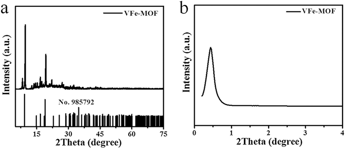
Fig. 2a presents the powder XRD pattern for the optimal VFe-MOF. The diffraction peaks at 9.0°, 14.2°, 15.9° and 18.0° can be indexed to the (200), (001), (201) and (201) planes of the MOFs phase, similar to the previously reported NiCo-based MOFs [31]. This result is consistent with the microstructure observed by HRTEM. Note that new peaks can be observed as the Fe content is more, possibly caused by Fe metal oxides or other impurities (Fig. S3 in Supporting information). Besides, the small-angle XRD pattern (Fig. 2b) of the MOF showed an obvious peak at 0.5°, which indicated that the material had mesoporous structure, being good for the access to the electrolyte.

|
Download:
|
| Fig. 2. (a) Powder XRD and (b) small-angle XRD patterns of the VFe-MOF. | |
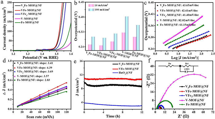
The electrocatalytic activity of VFe-MOF@NF (~0.742 mg/cm2 of loading) in OER was examined using a typical three electrode electrochemical workstation in the 1 mol/L KOH. Other contrast samples were also compared under the same conditions. Fig. 3a shows the LSV polarization curves. In order to avoid too large deviation of current curve, the scanning rate of 5 mV/s was used. It is worth noting that VFe-MOF@NF exhibits high OER activity and only needs a low overpotential of 246 mV for 10 mA/cm2, which is a good activity in OER electrocatalysts (more comparison see Table S3 in Supporting information) [26, 32-34]. In order to make the results more convincing, we also compared the overpotential of 100 mA/cm2, which supported that VFe-MOF@NF had the lowest overpotential no matter for 10 mA/cm2 or 100 mA/cm2 (Fig. 3b). The Tafel slope is also a key parameter to evaluate the catalytic activity of an OER catalyst. The water oxidation kinetics were assessed by Tafel plots obtained from LSV data (η = blog |j| + a, where b is the Tafel slope, j is the current density). As shown in Fig. 3c, the results displayed that the VFe-MOF@NF had a Tafel slope of 42.61 mV/dec, smaller than that of V3Fe-MOF@NF (43.65 mV/dec), VFe3-MOF@NF (41.40 mV/dec), V-MOF@NF (82.02 mV/dec) and Fe-MOF@NF (61.15 mV/dec). It indicates that VFe-MOF@NF has better OER catalytic activity, which may be due to the synergistic effect of V and Fe bimetal.

|
Download:
|
| Fig. 3. OER performance: (a) Polarization curves in 1 mol/L KOH with a scan rate of 5 mV/s; (b) The overpotential at 10 mA/cm2 and 100 mA/cm2; (c) Tafel plots; (d) The capacitive current at 0.10 V vs. Ag/AgCl as a function of scan rate; (e) Chronoamperometric curves of V3Fe-MOF@NF, VFe-MOF@NF and RuO2@NF at the overpotential; (f) Nyquist plots (The insert shows the equivalent circuit). | |
The catalytic performance of catalysts is interrelated to the exposed electrochemical active surface area (ECSA). Generally, ECSA was simulated via the double layer capacitance (Cdl) [35], since it is difficult to directly measure ECSA and there is a liner relationship between them. The Cdl was measured via CV in a potential range from 0.05 V to 0.15 V (vs. Ag/AgCl) with increasing scan rates. As shown in Fig. 3d, the Cdl (calculated from corresponding CV, Fig. S4 in Supporting information) of VFe-MOF@NF is 4.39 mF/cm2, which is much higher than that of V3Fe-MOF@NF (3.41 mF/cm2), VFe3-MOF@NF (3.69 mF/cm2), V-MOF@NF (3.57 mF/cm2), and Fe-MOF@NF (2.83 mF/cm2). This may be due to the exposure of more active sites in the VFe-MOF array grown vertically on the nickel foam substrate and the synergistic effect of V and Ni.
The ideal catalysts should not only have lower overpotential, lower Tafel slope and higher exchange current density, but also have higher stability. The development of electrocatalysts with high activity and high stability is very important for electrodes [36], because any commercial electrochemical systems must be stable in cycling. Therefore, the time dependent current density (I-t) curves of the VFe-MOF were measured. As shown in Fig. 3e, the I-t curves suggest that, compared with V3Fe-MOF@NF and RuO2@NF, the current density of VFe-MOF@NF has almost no obvious decrease, showing good stability during 12 h test. SEM and TEM tests were carried out to observe the change of catalyst microtopography before and after cycling (Fig. S5 in Supporting information). It can be observed that the array structure of the VFe-MOF@NF catalyst was generally maintained after 12 h OER testing because of the structure of the arrays supporting each other. However, the microstructure has been changed much, which was also observed in reported literature [37]. Fig. S6 (Supporting information) shows that the overall XPS spectra of the VFe-MOF before and after the initial cycles exhibit no obvious differences, except for the relative intensity of peak. The XPS data (Table S1 in Supporting information) of the VFe-MOF after the initial cycles shows that C, O, V and Fe content was 41.74 at%, 51.99 at%, 0.31 at% and 5.96 at%, respectively, distinct with the XPS data before the test. In addition, divided peak fitting analysis of Fe 2p shows that the intensity of Fe3+ is increased and a little shifted to a lower binding energy due to the oxidation activation after the beginning of OER [38]. Combined with the increase in O content, a possible explanation is that a fraction of V element separates out from the VFe-MOF during the OER process [39], and Fe is oxidized to FeOOH after the long-time OER, which have changed the microstructure of the MOFs [40, 41]. Again, despite of the changes, the stability of VFe-MOF@NF electrocatalyst is satisfactory in cycling. This suggests the OER stability test does not identify with the structural integrity; that is, even though the microstructures of MOFs used for elecrocatalysts may be changed, the active sites of the MOFs for OER can be retained and maintain activity [13, 42].
In order to study electrode dynamics and surface properties, EIS measurements of the synthesized catalysts were carried out at the potential of 0.47 V vs. RHE. The Nyquist plots (Fig. 3f) display that the VFe-MOF@NF has the minimal radius which means that it has the smallest polarization resistance. Furtherly, based on the fitting data of EIS (Table S2 in Supporting information), all electrocatalysts show similar mass transfer resistance (Rs, 2.436, 2.681, 3.01, 2.088 and 1.917 Ω for VFe-MOF@NF, VFe3-MOF@NF, V3Fe-MOF@NF, V-MOF@NF and Fe-MOF@NF, respectively), which can be attributed to the same electrolyte and Ni foam substrate. However, the charge transfer resistance (Rct, 4.019, 8.372, 4.814, 106.8 and 20.75 Ω for VFe-MOF@NF, VFe3-MOF@NF, V3Fe-MOF@NF, V-MOF@NF and Fe-MOF@NF, respectively) is very different, which indirectly indicates the different catalytic performance of the electrocatalysts. VFe-MOF@NF exhibits a much smaller diameter of semicircle than that of the other four MOFs, suggesting a better conductivity and faster electrode dynamics. It can be concluded that the combination of the arrays' microstructure, synergistic effect of V and Fe bimetal and a highly conductive Ni substrate contribute to the outstanding electrocatalytic kinetics of the VFe-MOF@NF electrode.
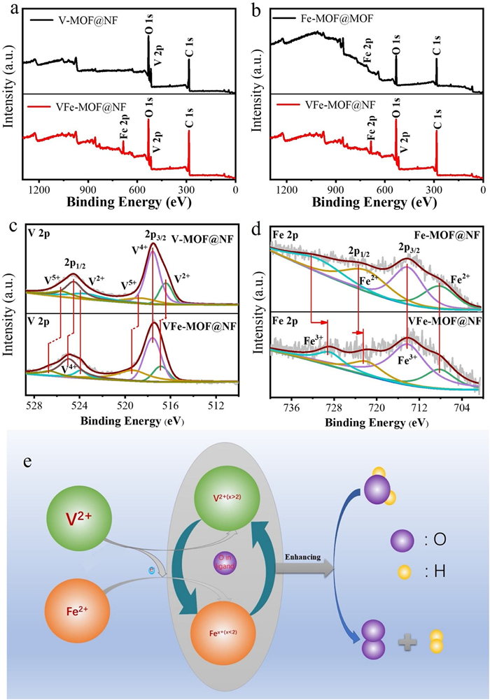
To further illustrate the synergistic effect of V and Fe bimetals, XPS measurement was performed on the MOFs. The survey spectrum of VFe-MOF@NF was compared with V-MOF@NF and Fe-MOF@NF respectively (Figs. 4a and b). From the full XPS spectrum of VFe-MOF@NF, it indicates the existence of V, Fe and O elements, which is consistent with the analysis results of EDS elemental mapping images. According to XPS data (Table S1), the V: Fe molar ratio of initial VFe-MOF@NF in the surface is 1.68:1, which is different from ICP data, indicating that Fe element maybe has surface segregation phenomenon. As can be seen in Fig. 4c, the V2+ (516.88, 519.44, 525.05, 526.73 eV for VFe-MOF@NF, respectively) peaks shift to higher compared with the binding energies of V2+ (516.42, 518.84, 524.52, 525.67 eV for V-MOF@NF, respectively). On the contrary, the Fe2+ (722.52, 729.20 eV for VFe-MOF@NF, respectively) peaks shift to lower binding energies compared with the binding energies of Fe2+ (723.46, 732.30 eV for Fe-MOF@NF, respectively) (Fig. 4d). This is suggesting that the partial electrons are transferred from V2+ to Fe2+ through the oxygen of the ligands, and the internal electronic structure of the VFe-MOF@NF has been adjusted [43-45]. In addition, the valence-shell electrons of Fe2+ is 3d6, containing unpaired electrons, which can interact with O2− through the π-bond. However, the d-orbitals of V2+ is a 5-fold degenerate orbital, repelling each other with O2−, which is easier to lose electrons to weaken the repulsion. After combination of V2+ and Fe2+ (Fig. 4e), the repulsion between O2− and V2+ will increase the π-bond of Fe-O, which will induce a partial charge transfer from V2+ to Fe2+, consistent with the results of XPS (Figs. 4c and d). Therefore, appropriately reducing and increasing the valence state of Fe and V atoms can weaken the excessive adsorption capacity of Fe2+ on OH−, and enhance the adsorption capacity of V2+ on OH−, accelerating the charge transfer and mass transfer, and synergistically increasing the activity of OER.

|
Download:
|
| Fig. 4. XPS spectra for VFe-MOF@NF and (a) V-MOF@NF, and (b) Fe-MOF@NF. Corresponding (c) V 2p and (d) Fe 2p regions. (e) Schematic representation of the synergistic effect between V and Fe in VFe-MOF@NF. | |
Furtherly, electrochemical experiments have verified the importance of the V and Fe bimetal MOFs to the enhancement of OER activity. Compared with the V-MOF@NF and Fe-MOF@NF, VFe-MOF@NF exhibited higher electrocatalytic activity.
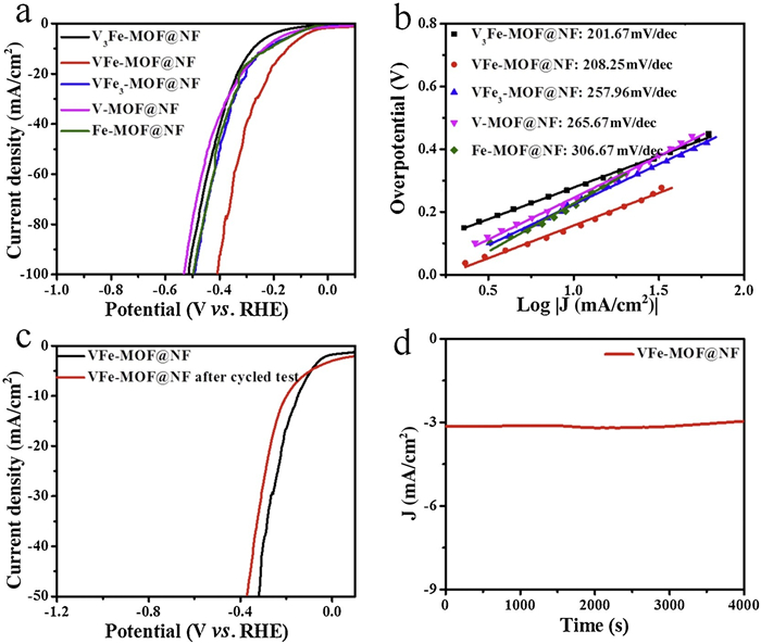
In order to further explore the applicability of the VFe-MOF@NF catalyst in the overall water splitting process, HER properties of the electrocatalyst were studied. The test was also carried out in 1 mol/L KOH, same to that of OER. The use of the same electrolyte in HER and OER facilitates subsequent combination of the two electrodes to achieve overall water splitting. Fig. 5a shows the polarization curves of V3Fe-MOF@NF, VFe-MOF@NF, VFe3-MOF@NF, V-MOF@NF and Fe-MOF@NF in HER. As expected, the VFe-MOF@NF catalyst showed the best electrochemical performance compared to other samples. The VFe-MOF@NF can reach a current density of 10 mA/cm2 at a low overpotential of 147 mV. Fig. 5b presents the Tafel plots of all the as-synthesized catalysts. The Tafel slope of VFe-MOF@NF catalyst is 208.25 mV/dec, which is smaller than that of VFe3-MOF@NF (257.96 mV/dec), V-MOF@NF (265.67 mV/dec), and Fe-MOF@NF (306.67 mV/dec), suggesting that the VFe-MOF@NF electrode has an outstanding HER dynamics. The VFe-MOF@NF electrode shows comparable properties to many other non-precious HER catalysts reported in alkaline electrolyte (Table S4 in Supporting information) [46-49]. Just like OER, the long-term durability of the VFe-MOF@NF catalyst for HER was also considered as a crucial factor for practical applications. Fig. 5c shows that the current density displayed a very limit change after stability test, indicating a favorable cycling performance of the VFe-MOF@NF. Moreover, the time-dependent current density curve (Fig. 5d) suggested that the activity of the VFe-MOF@NF catalyst shows excellent stability after a continuous 4000 s HER test, without significant decline. The experimental results above illustrate that the VFe-MOF@NF catalyst has satisfactory catalytic activity and long-term stability for HER in alkaline electrolyte, which is due to the synergistic effect of V and Fe bimetals.

|
Download:
|
| Fig. 5. HER performance: (a) Polarization curves in 1 mol/L KOH with a scan rate of 5 mV/s; (b) Tafel plots; (c) Polarization curves of the VFe-MOF@NF before and after stability test; (d) Chronoamperometric curves of VFe-MOF@NF at the overpotential. | |
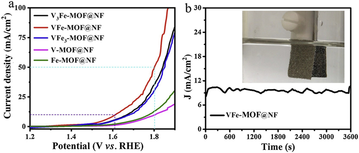
From the above discussion, the VFe-MOF@NF electrode displayed excellent OER and satisfactory HER performance in the same alkaline solution. The excellent catalytic properties could be attributed to its unique array structure and synergistic effect of V and Fe bimetals, providing many active sites and promoting the mass transport. Accordingly, such electrode can be used as the anode and cathode electrocatalysts for overall water splitting. Therefore, an electrolytic cell of a two-electrode system was assembled, using the VFe-MOF@NF electrode as both anode and cathode (The loading density of VFe-MOF@NF for anode and cathode is 0.742 mg/cm2, respectively). In the process of electrolyzing water, electrons are transferred from the anode to the cathode, generating oxygen at the anode and hydrogen at the cathode. As shown in Fig. 6a, the VFe-MOF@NF||VFe-MOF@NF couple only needs a cell voltage of 1.61 or 1.80 V to reach a catalytic current density of 10 or 50 mA/cm2, which represents a good performance in the bi-functional catalysts recently reported for overall water splitting (more comparison see Table S5 in Supporting information) [50-55]. Furthermore, in order to prove its wide applicability in multifunctional electronic devices, its stability must be tested in 1 mol/L KOH. As shown in Fig. 6b, the current density has no obvious degradation after 3600 s of continuous water splitting reaction, indicating the remarkable high electrochemical stability of the VFe-MOF@NF||VFe-MOF@NF couple for overall water splitting (the inset photograph shows the two-electrode configuration used for the overall water splitting reaction). The above results show that the VFe-MOF@NF electrode has potential applications in energy-efficient and low-cost overall water splitting electrolysis.

|
Download:
|
| Fig. 6. Water splitting performance: (a) Linear sweeping voltammetry curves of VFe-MOF@NF as anode and cathode catalyst in 1 mol/L KOH for overall water splitting; (b) The current-time (I-t) curves of VFe-MOF@NF at the constant potential for 3600 s (inset: the optical photograph for overall water splitting reaction in a two-electrode configuration). | |
In summary, vanadium-iron bimetal organic frameworks with well-defined array structure have been successfully prepared on nickel foam. The as-fabricated VFe-MOF@NF electrode exhibits excellent electrocatalytic activity and durability for OER and HER in alkaline medium. The overpotentials of 10 mA/cm2 are 246 mV for OER and 147 mV for HER, respectively. The electrolyzer made from VFe-MOF@NF electrode as both the cathode and anode in 1 mol/L KOH needs only a voltage of 1.61 V to reach a current density of 10 mA/cm2. The superior performance of VFe-MOF@NF can be attributed to the morphological control and electronic regulation, that is, 1) the exposure of the active sites at electrocatalyst/electrolyte interfaces due to the array structure; 2) the synergistic effect of vanadium and iron metals in the homogeneous structure. This simple method of designing efficient electrocatalysts can be applied to various fields such as fuel cells and lithium-ion batteries.
Declaration of competing interestThe authors declare that they have no known competing financial interests or personal relationships that could have appeared to influence the work reported in this paper.
AcknowledgementsThis work was supported by the National Natural Science Foundation of China (No. 51502347), the Science Foundation of the University of Science and Technology Beijing (No. 06500045) and the research funds of the University of Science and Technology Beijing (No. FRF-GF-19-006B).
Appendix A. Supplementary dataSupplementary material related to this article can be found, in the online version, at doi:https://doi.org/10.1016/j.cclet.2020.12.015.
| [1] |
W. Ye, Y. Yang, X. Fang, et al., ACS Sustain. Chem. Eng. 7 (2019) 18085-18092. DOI:10.1021/acssuschemeng.9b05126 |
| [2] |
M. Wang, M. Wang, Y. Fu, et al., Chin. Chem. Lett. 28 (2017) 2207-2211. DOI:10.1016/j.cclet.2017.11.037 |
| [3] |
T. Zhang, J. Du, P. Xi, et al., ACS Appl. Mater. Interfaces 9 (2017) 362-370. DOI:10.1021/acsami.6b12189 |
| [4] |
P. Chen, T. Zhou, M. Zhang, et al., Adv. Mater. 29 (2017) 1701584. DOI:10.1002/adma.201701584 |
| [5] |
W. Qiao, W. Xu, X. Xu, et al., ACS Appl. Energy Mater. 3 (2020) 2315-2322. DOI:10.1021/acsaem.0c00163 |
| [6] |
L. Ai, J. Su, M. Wang, et al., ACS Sustain. Chem. Eng. 6 (2018) 9912-9920. DOI:10.1021/acssuschemeng.8b01120 |
| [7] |
X. Chen, X. Zhen, H. Gong, et al., Chin. Chem. Lett. 30 (2019) 681-685. DOI:10.1016/j.cclet.2018.09.017 |
| [8] |
U.K. Sultana, A.P. O'Mullane, ChemElectroChem 6 (2019) 2630-2637. DOI:10.1002/celc.201801731 |
| [9] |
G. Wei, K. Du, X. Zhao, et al., Chin. Chem. Lett. 31 (2020) 2641-2644. DOI:10.1016/j.cclet.2020.02.029 |
| [10] |
J. Xu, M. Wang, F. Yang, et al., Inorg. Chem. 58 (2019) 13037-13048. DOI:10.1021/acs.inorgchem.9b01953 |
| [11] |
C. Du, Y. Men, X. Hei, et al., ChemElectroChem 5 (2018) 2564-2570. DOI:10.1002/celc.201800630 |
| [12] |
L. Zeng, L. Yang, J. Lu, et al., Chin. Chem. Lett. 29 (2018) 1875-1878. DOI:10.1016/j.cclet.2018.10.026 |
| [13] |
J. Xu, X. Zhu, X. Jia, ACS Sustain. Chem. Eng. 7 (2019) 16629-16639. DOI:10.1021/acssuschemeng.9b03952 |
| [14] |
B. You, N. Jiang, M. Sheng, et al., Chem. Mater. 27 (2015) 7636-7642. DOI:10.1021/acs.chemmater.5b02877 |
| [15] |
X. Zhao, P. Pachfule, S. Li, et al., Angew. Chem. Int. Ed. 57 (2018) 8921-8926. DOI:10.1002/anie.201803136 |
| [16] |
D. Ding, K. Shen, X. Chen, et al., ACS Catal. 8 (2018) 7879-7888. DOI:10.1021/acscatal.8b02504 |
| [17] |
H.B. Wu, X.W. Lou, Sci. Adv. 3 (2017) eaap9252. DOI:10.1126/sciadv.aap9252 |
| [18] |
V. Maruthapandian, S. Kumaraguru, S. Mohan, et al., ChemElectroChem 5 (2018) 2795-2807. DOI:10.1002/celc.201800802 |
| [19] |
Y. Wang, B. Zhang, W. Pan, et al., ChemSusChem 10 (2017) 4170-4177. DOI:10.1002/cssc.201701456 |
| [20] |
C. Sun, Q. Dong, J. Yang, et al., Nano Res. 9 (2016) 2234-2243. DOI:10.1007/s12274-016-1110-1 |
| [21] |
D. Senthil Raja, X.F. Chuah, S.Y. Lu, Adv. Energy Mater. 8 (2018) 1801065. DOI:10.1002/aenm.201801065 |
| [22] |
H. Zhang, J. Su, K. Zhao, et al., ChemElectroChem 7 (2020) 1805-1824. DOI:10.1002/celc.202000136 |
| [23] |
Y. Fu, L. Xu, H. Shen, et al., Chem. Eng. J. 299 (2016) 135-141. DOI:10.1016/j.cej.2016.04.102 |
| [24] |
W. Wang, X. Xu, W. Zhou, et al., Adv. Sci. 4 (2017) 1600371. DOI:10.1002/advs.201600371 |
| [25] |
H.-W. Lin, D. Senthil Raja, X.F. Chuah, et al., Appl. Catal. B 258 (2019) 118023. DOI:10.1016/j.apcatb.2019.118023 |
| [26] |
K. Rui, G. Zhao, Y. Chen, et al., Adv. Funct. Mater. 28 (2018) 1801554. DOI:10.1002/adfm.201801554 |
| [27] |
L. Jiao, Y. Wang, H.L. Jiang, et al., Adv. Mater. 30 (2018) 1703663. DOI:10.1002/adma.201703663 |
| [28] |
L. Han, J. Xu, X. Zhu, et al., Mater. Today Energy 16 (2020) 100419. DOI:10.1016/j.mtener.2020.100419 |
| [29] |
G. Cai, W. Zhang, L. Jiao, et al., Chemistry 2 (2017) 791-802. DOI:10.1016/j.chempr.2017.04.016 |
| [30] |
J. Duan, S. Chen, C. Zhao, Nat. Commun. 8 (2017) 15341. DOI:10.1038/ncomms15341 |
| [31] |
S. Zhao, Y. Wang, J. Dong, et al., Nat. Energy 1 (2016) 16184. DOI:10.1038/nenergy.2016.184 |
| [32] |
M. Jahan, Z. Liu, K.P. Loh, Adv. Funct. Mater. 23 (2013) 5363-5372. DOI:10.1002/adfm.201300510 |
| [33] |
X. Zhao, B. Pattengale, D. Fan, et al., ACS Energy Lett. 3 (2018) 2520-2526. DOI:10.1021/acsenergylett.8b01540 |
| [34] |
M. Cai, X. Lu, Z. Zou, et al., ACS Sustain. Chem. Eng. 7 (2019) 6161-6169. DOI:10.1021/acssuschemeng.8b06360 |
| [35] |
J. Zhou, Y. Dou, A. Zhou, et al., ACS Energy Lett. 3 (2018) 1655-1661. DOI:10.1021/acsenergylett.8b00809 |
| [36] |
J. Zheng, W. Zhou, T. Liu, et al., Nanoscale 9 (2017) 4409-4418. DOI:10.1039/C6NR07953A |
| [37] |
Y. Shi, Y. Yu, Y. Liang, et al., Angew. Chem. Int. Ed. 58 (2019) 3769-3773. DOI:10.1002/anie.201811241 |
| [38] |
W. Li, S. Watzele, H.A. El-Sayed, et al., J. Am. Chem. Soc. 141 (2019) 5926-5933. DOI:10.1021/jacs.9b00549 |
| [39] |
C. Kuai, Z. Xu, C. Xi, et al., Nat. Catal. 3 (2020) 743-753. DOI:10.1038/s41929-020-0496-z |
| [40] |
W. Zhu, X. Yue, W. Zhang, et al., Chem. Commun. 52 (2016) 1486-1489. DOI:10.1039/C5CC08064A |
| [41] |
W. Zhou, X.J. Wu, X. Cao, et al., Energy Environ. Sci. 6 (2013) 2921-2924. DOI:10.1039/c3ee41572d |
| [42] |
Y. Li, X. Du, J. Huang, et al., Small 15 (2019) 1901980. DOI:10.1002/smll.201901980 |
| [43] |
J. Liu, Y. Ji, J. Nai, et al., Energy Environ. Sci. 11 (2018) 1736-1741. DOI:10.1039/C8EE00611C |
| [44] |
H.Y. Wang, Y.Y. Hsu, R. Chen, et al., Adv. Energy Mater. 5 (2015) 1500091. DOI:10.1002/aenm.201500091 |
| [45] |
Z. Zou, T. Wang, X. Zhao, et al., ACS Catal. 9 (2019) 7356-7364. DOI:10.1021/acscatal.9b00072 |
| [46] |
X. Wang, W. Zhou, Y.P. Wu, et al., J. Alloys Compd. 753 (2018) 228-233. DOI:10.3390/pr6110228 |
| [47] |
J.W. Tian, M.X. Fu, D.D. Huang, et al., Inorg. Chem. Commun. 95 (2018) 73-77. DOI:10.1016/j.inoche.2018.07.009 |
| [48] |
Y. Wang, S. Li, Y. Chen, et al., Appl. Surf. Sci. 505 (2020) 144503. DOI:10.1016/j.apsusc.2019.144503 |
| [49] |
M. Li, H. Wang, Y. Zhu, et al., Appl. Surf. Sci. 496 (2019) 143672. DOI:10.1016/j.apsusc.2019.143672 |
| [50] |
Y. Xie, M. Chen, M. Cai, et al., Inorg. Chem. 58 (2019) 14652-14659. DOI:10.1021/acs.inorgchem.9b02333 |
| [51] |
F. Wang, J. Chen, X. Qi, et al., Appl. Surf. Sci. 481 (2019) 1403-1411. DOI:10.1016/j.apsusc.2019.03.200 |
| [52] |
C. Tang, N. Cheng, Z. Pu, et al., Angew. Chem. Int. Ed. 54 (2015) 9351-9355. DOI:10.1002/anie.201503407 |
| [53] |
L. Ma, K. Zhang, S. Wang, et al., Appl. Surf. Sci. 489 (2019) 815-823. DOI:10.1016/j.apsusc.2019.06.044 |
| [54] |
J. Hu, Y. Ou, Y. Li, et al., ACS Sustain. Chem. Eng. 6 (2018) 11724-11733. DOI:10.1021/acssuschemeng.8b01978 |
| [55] |
Z. Tao, T. Wang, X. Wang, et al., ACS Appl. Mater. Interfaces 8 (2016) 35390-35397. DOI:10.1021/acsami.6b13411 |