 2021, Vol. 32


b Academy of Fundamental and Interdisciplinary Sciences, Harbin Institute of Technology, Harbin 150001, China
Overview various energy storage technologies, rechargeable batteries are considered to be one of the most reliable and practicable equipment [1-5]. Lithium metal batteries (LMB) have high theoretical energy density, which is originated from the high theoretical specific capacity of Li metal (3860 mAh/g), low redox potential (-3.04 V vs. SHE) and low mass density (0.534 g/cm2) [6-8]. Thus, lithium metal anodes have drawn the attention of substantial research institutions. Despite its amazing advantages, lithium metal anodes still have some serious problems limited their commercial applications. (i) The uneven plating of Li+ on the surface of the host material of anode gives rise to the formation of Li dendrite, which piercing the separator, causing short circuits and safety risks of the batteries [9-11]. (ii) The volume expansion of Li has enormous change through the process of plating and stripping, which seriously affects the cycle life of LMB [12]. (iii) The continuous side reactions between the liquid electrolyte and Li metal consume a large amount of active Li, resulting in the production of "dead Li" and repeated accumulation/destruction of the solid electrolyte interphase (SEI), leading to irreversible expenditure of active Li metal and lower coulombic efficiency [13, 14]. Therefore, finding a suitable method to relieve or even restrain the formation of Li dendrites, improve the coulombic efficiency and extend the cycle life of the electrodes is imminently.
Aiming to the modification of anode, researchers have made many efforts to design corresponding strategies. Different electrolyte additives were found to make the interface structure more stable [15-22] and artificial SEI film was constructed to adjust the transport flux of Li+ [23-28]. Conductive framework or modified current collector fluid was constructed to enhance its affinity with the lithium, uniform distribution of Li ions on the interface and restrain the formation of Li dendrites [29]. Various materials, such as porous copper [30], nickel foam [31], carbon and its derivatives [32-37], have been widely studied in recent years. Carbon materials stand out due to their strong feasibility to improve the electrodeposition behavior of lithium metal anodes. Among them, CNT has been widely used as the host materials of lithium anode owing to its light weight, favorable stability and outstanding conductivity [32, 38-41]. However, the weakly lithiophilic and uneven distribution of lithium ions result in the hidden danger of lithium dendrite. Another key issue is catalysts must be added to catalyze the growth of carbon nanotubes in previous reports [33, 39]. Therefore, designing and preparing easy synthesized, lithiophilic CNT-based anode to manufacture high specific capacity lithium metal batteries is a promising strategy.
Herein, we prepared a lithiophilic arrays N-CNT@SS composite anode by using metal iron in stainless steel fiber to catalyze melamine to form N-CNT without any additional catalyst. Self-growing N-CNTs provide a large number of N-functional groups [42], which enrich nucleation sites of lithium, inhibiting the formation of lithium dendrites. Meanwhile, the array structure further increases the specific surface area of the composite anode, decreases the local current density, which makes deposition of lithium more uniform on the anode. In addition, the interpenetrating nanotubes network provides a wealth of bridging channels to facilitate the transmission of electrons in anode. COMSOL multiphysics field simulation further confirmed that the N-CNT array regulate lithium-ion flux, which prompts uniformly deposition of lithium on the anode and inhibits the formation of lithium dendrite. Due to the synergism of the above advantages, the N-CNT@SS anode sustains coulombic efficiency over 98.9% last without dendrites for 300 cycles at current density of 1 mA/cm2, low polarization, high specific capacity and outstanding cycle stability. Full cells were assembled employing the LiFePO4 (LFP) as the cathode, N-CNT@SS as the anode, displaying cycling stability with a capacity of 152.33 mAh/g and capacity retaining ratio of 95.4% after 100 cycles at 0.5 C.
N-CNT@SS anode was synthesized by one-step method. The stainless steel mesh with the same size of the boat is placed on a ceramic boat with 1.3 g melamine powder. The boat is located in the tubular furnace at 600 ℃ for 2 h before thermal annealing at 700 ℃ for 1 h in Ar flow at atmospheric pressure. In this process, melamine is heated and decomposed into C3N4 on the surface of stainless steel mesh. Nitrogen-doped carbon nanotubes are synthesized by self-catalysis at Fe catalytic sites.
The manufacture of self-catalytic N-CNT@SS is shown in Fig. S1 (Supporting information). The carbon and nitrogen elements of carbon nanotube (CNT) were supplied by melamine by chemical vapor deposition (CVD) using iron as catalyst site on stainless steel mesh. The CNTs were calcined in 700 degree through Ar atmosphere and self-catalyzed in situ growth at high temperature.
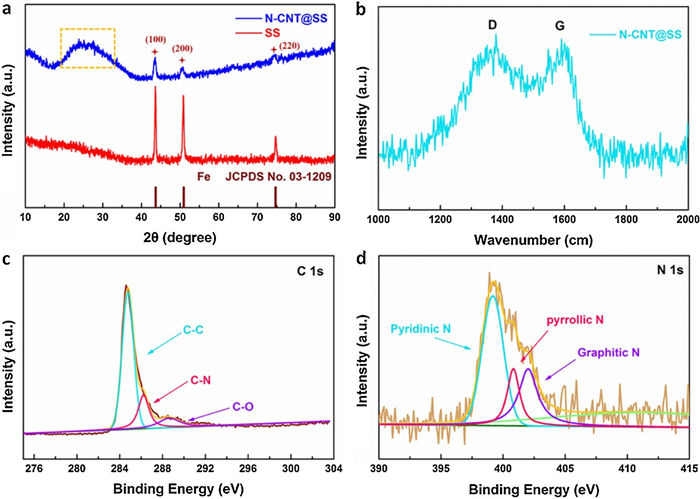
The X-ray diffraction (XRD) pattern of the primary stainless steel mesh substrate and self-catalytic N-CNT@SS are shown in Fig. 1a. The diffraction peaks at 43.69°, 50.97° and 74.67° can be attributed to (111), (200) and (220) of Fe (JPCDS card No. 03-1209), respectively, corresponding to stainless steel mesh substrate. The distribution of Fe and C are consistent, which confirms the mechanism of self-catalysis (Figs. S1g and i). It is obvious that the wide shoulder peak (orange square) is close to 25°, which represents the diffraction peak of graphite like crystal of amorphous carbon, proves the existence of amorphous carbon in N-CNT@SS. Raman spectroscopy was also measured to evaluate the graphitization of N-CNT (Fig. 1b). The two main peaks of 1345 cm−1 and 1590 cm−1 are correlated with D and G bands respectively. The high value of ID/IG (1.04) indicates that N-CNT has a high graphitization degree and great conductivity, which proves that the introduction of N-CNT further enhances the electronic conductivity of SS base. X-ray photoelectron spectroscopy (XPS) is used to indicate the self- catalytic N-CNT @ SS. As manifested in the high-resolution C 1s spectrum, the peaks at 284.7 eV, 286.2 eV and 288.6 eV can be distributed to carbon in the form of C-C (sp3), C-N (sp3) and C=O (sp2), respectively (Fig. 1c). A high-resolution N 1s spectrum (Fig. 1d) is also obtained to acknowledge the successful doping of nitrogen and the existence formation of nitrogen in N-CNT. The results show that the typical N groups include pyridine N (399.5 eV), pyrrole N (400.8 eV) and graphite N (402.1 eV). The pyridinic N have lone-pair electrons, which are doped into carbon nanotubes to serve as electron-rich donors and Lewis bases, intensely adsorbing Lewis acidic Li ions from the electrolyte through acid-base interaction, providing abundant Li nucleation sites on the surface of anode to guide uniform deposition [43, 44]. According to the detailed results obtained by XPS, the atomic content of N accounts for 3.6% of the N-CNT@SS anode, as shown in the Table S1 (Supporting information).

|
Download:
|
| Fig. 1. (a) XRD patterns of SS and N-CNTs@SS. (b) Raman spectrum of N-CNTs@SS. XPS spectrum of (c) C 1s (d) N 1s of N-CNTs@SS. | |
To reveal the contribution of N-CNT@SS to the inhibition of dendrite during deposition of lithium, we carried out plating/stripping test on Li metal anode. The morphology is recorded by SEM. As shown in Fig. S2 (Supporting information), under the current density of 1 mA/cm2 and surface capacity of 1 mAh/cm2, the diameter of smooth Li "island" is about 1 μm and fully filled with N can be observed during the fifth cycle of lithium plating.
The N-CNT@SS framework plays a crucial role in limiting the dendrite of Li from two aspects: 1) The N-CNT provides a quantity number of N functional groups, which enhances the lithium affinity of stainless steel mesh base, and provides a large number of nucleation sites, which is conducive to the distribution and deposition of Li+. 2) The existence of carbon nanotube further increases the specific surface area of the stainless steel mesh, provides enough free space for volume change, at the same time, the stable structure also guarantees for prolonging the battery life.
Under the condition of constant current density at 1 mA/cm2 and area capacity at 1 mAh/cm2, constant current charging and discharging tests were implemented to evaluate cycle stability and lithium plating/stripping efficiency. The coulombic efficiency of bare SS began to decay at 140 cycles, while the N-CNT@SS electrode was stable at 98.9% and lasted to 300 cycles. (Fig. 2a) The effect of N-CNT@SS electrode modification on the dendrite behavior of Li was studied by means of cycle life, polarization voltage and total voltage delay of symmetrical coin lithium metal battery. The measurements show that the N-CNT@SS electrodes sustain more than 300 cycles (600 h) at current density of 1 mA/cm2 and surface capacity of 1.0 mAh/cm2 (Fig. 2b). The voltage curves obtained at the cycle windows of 50th, 100th and 200th (Figs. 2c-e) show that all voltage delays of bare SS are higher than those of N-CNT@SS at 50 cycles and 100 cycles (449.4 mV vs. 270.8 mV, 936.2 mV vs. 1539 mV), respectively. The voltage fluctuation is tiny small after 200 cycles, indicating that the N-CNT@SS electrode has superior cyclic stability. The initial nucleation during lithium deposition is significant for the electrochemical performance of the lithium batteries.

|
Download:
|
| Fig. 2. Cycling performance of N-CNTs@SS anode. (a) Coulombic efficiency and (b) voltage–time curves of 1.0 mAh/cm2 lithium plated/stripped on the N-CNTs@SS at a current density of 1.0 mA/cm2. The magnified profiles at the (c) 50th, (d) 100th, (e) 200th cycles with comparing the voltage hysteresis and the polarization potential of the discharging platform. The Nyquist plot of electrochemical impedance spectra of (f) Li||SS, (g) Li||N-CNT@SS half cells at current density of 1 mA/cm2 while the areal capacity is 1 mAh/cm2 after different cycles. (h) Rs and (i) Rct of N-CNT@SS at cycle number of 0, 1st, 5th, 10th, 50th. | |
The resistance of N-CNT@SS is much lower than that of bare SS due to the large amount of lithium-friendly nitrogen in the N-CNT@SS, confirmed by the Nyquist curve of SS and N-CNT@SS electrode (Figs. 2f and g). At both conditions, N-CNT@SS symmetrical batteries exhibit smaller semicircles than SS batteries at high frequencies, regardless of initial conditions or after lithium plating/stripping of cycles, indicating that the SEI interface impedance of N-CNT@SS is smaller as well as the charge transfer resistance of the surface of Li metal is smaller than SS, respectively. For each electrode, lithium plating/stripping can significantly reduce the charge transfer resistance (Rct) of the electrode, and the Rct of N-CNT@SS decreases more than SS, indicating that with cycles, the transport rate of lithium ion through SEI became faster (Figs. 2h and i). The addition of nitrogen-doped carbon nanotubes increases the ionic conductivity of the interface between anode and electrolyte, providing a fast transport channel of lithium ions, guiding lithium ions uniform deposition effectively, which accord with the voltage delay in Figs. 2c and d.
Li "island" was formed by lithium plating on N-CNT@SS under the current density of 1 mA/cm2, areal capacity of 1 mAh/cm2 in Fig. S2 (Supporting information). The SEM image failed show the initial state of Li nucleation. In order to explore the state of Li nucleation and growth on N-CNT@SS substrate, we used Li anode, SS and N-CNT@SS to test the electrochemical performance of Li|SS, Li|N-CNT@SS half battery of electrode under different current densities, with area capacity of 1 mAh/cm2, respectively (Fig. 3).

|
Download:
|
| Fig. 3. SEM images of lithium deposition layers with the different current densities of 0.2 mA/cm2 at (a) SS and (e, i) N-CNT@SS, 0.5 mA/cm2 at (b) SS and (f, j) N-CNT@SS, 1 mA/cm2 at (c) SS and (g, k) N-CNT@SS, 2 mA/cm2 at (d) SS and (h, l) N-CNT@SS. The areal capacities are 1 mAh/cm2. | |
Under the current density of 0.2 mA/cm2, dendrite formation obviously appeared on the bare SS electrode (Fig. 3a). By contrast, Li+ migrates to the surface of N-CNT, and abundant n provides a major number of nucleation sites for Li. As shown in Figs. 3e and i, it can be observed that as the deposition diameter of Li increases, Li is deposited outside the tube wall. When the current density up to 0.5 mA/cm2, the migrating number of Li+ on the surface of the tube increases in the same time when the tube wall overloaded (Figs. 3f and j). The extra Li is deposited between the tubes, and the tubes are connected gradually. The morphology of dendrite on bare SS still exists without significantly change (Fig. 3b). When the current density increases to 1 mA/cm2, it is obvious that the deposition of Li+ is still uniform, which gradually fill the gap of N-CNTs in a smooth shape. When the current density increases to 2 mA/cm2, "donuts" are connected with abundant Li, filling its gap, forming a typical Li "island" structure, and further fills the pores of SS base without dendrite (Figs. 3h and l). At the same time, more and more dendrites are found on the surface of bare SS electrode may due to the rapid current growth promoting the influence of tip effect, which show in Figs. 3c and d. COMSOL multiphysics field simulation is carried out to theoretically demonstrate the mechanism of SS and N-CNT for plating of lithium ion (Fig. S3 in Supporting information), the relevant data are listed in Table S2 (Supporting information).
Therefore, we deduce that the initial process of Li nucleation on N-CNT@SS is to deposit outward the tube wall first, which named N-CNT@SS/Li-i. With the migration of Li+ increasing, Li begins to deposit between the tube walls, gradually connects with each other to form a ring, namely "doughnut" shape. Finally, the process of Li nucleation and growth is completed on the surface dendrite-free Li "island".
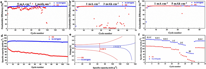
When the deposition areal capacity is 1 mAh/cm2 and the current density is 1 mA/cm2, the coulombic efficiency of N-CNT@SS can be stabilized at 98.9% for 300 cycles (Fig. 2a), and current density at 5 mA/cm2, the coulombic efficiency of N-CNT@SS can be stabilized at 98.6% for 150 cycles (Fig. 4a). In contrast, at 1 mA/cm2, the coulombic efficiency decreases rapidly to below 90% after 130 cycles of bare SS, and shows a continuous decline trend. Under the current density of 5 mA/cm2, the coulombic efficiency fluctuates at about 90%, then drops to 20% even below after 90 cycles. An explanation is that the surface of bare SS is lithiophobic, which leads to the uneven distribution of Li+ flow and high local current density. Tip effect causes the formation of dendrites. Along with the growth of Li dendrites by degrees, continuous reviving of SEI consumed a large amount of Li, leading to low coulombic efficiency. At the same time, lithium dendrites give rise to isolated "dead lithium", which leads to irreversible lithium consumption. On the contrary, N-CNT@SS electrode can retain stable coulombic efficiency at high current density. The plating / stripping process of lithium metal on the anode is characterized by cyclic voltammetry (CV) on Li|SS and Li||N-CNT@SS cell (Fig. S4 in Supporting information).

|
Download:
|
| Fig. 4. Coulombic efficiencies of Li plating/striping on N-CNT@SS and SS (a) at current density of 5 mA/cm2 while areal capacity is 1 mAh/cm2, at different areal capacities of (b) 3 mAh/cm2, (c) 5 mAh/cm2 while the current densities are 1 mA/cm2. (d) The cycling performance and (e) charge/discharge curves of SS@Li-LFP and N-CNT@SS@Li-LFP at the rate of 0.5 C. (f) The rate capability of SS@Li-LFP and N-CNT@SS@Li-LFP at the rates of 0.1, 0.2, 0.5, 1, 2 and 5 C. | |
The influence of different capacity for the performance of the battery is also discussed. While the current density is 1 mA/cm2, the coulombic efficiency of N-CNT@SS can be stabilized at 98.9% for 300 cycles at 1 mAh/cm2 (Fig. 3a), at 98.8% for 85 cycles at 3 mAh/cm2 (Fig. 4b), and at 98.8% for 55 cycles at 5 mAh/cm2 (Fig. 4c). In contrast, the coulombic efficiency of SS decreases rapidly to less than 90% for 130 cycles at a deposition areal capacity of 1 mAh/cm2, and continues declining. Under the current density of 3 mA/cm2, 5 mA/cm2, the coulombic efficiency of SS decreases significantly at 23 cycles and 33 cycles respectively.
To evaluate the practical application of N-CNTs@SS electrode, we used LiFePO4 (LFP) as cathode and N-CNTs@SS as anode to assemble the full cell (N-CNT@SS@Li-LFP). For comparison, SS and LiFePO4 were also assembled into the cell (SS@Li-LFP). Among them, N-CNTs@SS and SS pre-plating Li for 15 mAh/g respectively. As shown in Figs. 4d and e, the cycle performance of the battery is conducted through constant current charging/discharging with a current density of 0.5 C in the voltage range of 2.4–4.2 V. The initial capacity of N-CNT@SS@Li-LFP was 151.21 mAh/g, and then increased to by cycles, reaching at the peak of 13th cycles. After 100 cycles, the capacity of N-CNT@SS@Li-LFP remained at 152.33 mAh/g, capacity retaining ratio is 95.4% with high coulombic efficiency of 99.8%. However, the initial capacity of SS@Li-LFP is relatively low of 109.26 mAh/g, gradually decreasing by cycles. After 100 cycles, it has decreased to 46.99 mAh/g, and the capacity retaining ratio is only 43%. Facts above show that N-CNT@SS has favorable Li utilization, which can restrain the generation of lithium dendrites and reduce the produce of "dead" lithium. The charge and discharge voltage curves of the batteries can effectively reflect the polarization degree of the electrode. At 0.5 C, as shown in Fig. 4e, the N-CNT@SS@Li-LFP provides low polarization of only 0.11 V, but the SS@Li-LFP battery polarization reaches 0.50 V, indicating that the surface area of SS electrode without N-CNT gathers uncontrollable lithium dendrites, resulting in irreversible capacity. The rate performance of N-CNT@SS@Li-LFP and SS@Li-LFP is shown in Fig. 4f. The capacity of N-CNT@SS@Li-LFP are 169.31, 166.48, 159.83, 151.07, 137.94 and 73.50 mAh/g respectively at 0.1, 0.2, 0.5, 1, 2 and 5 C. Under each rate, N-CNT@SS@Li-LFP has higher and more stable capacity than SS@Li-LFP. After changes of a series of rate, the capacity of N-CNT@SS@Li-LFP is 157.03 mAh/g, which shows excellent rate performance. In the full battery, no obvious change in the surface of the cathode before and after the cycle (Figs. S7, S8c and d in Supporting information). But dendrite is produced in SS anode, and lithium uniformly deposit on the surface of N-CNT@SS anode without dendrite (Figs. S8a and b in Supporting information), which indicates that the performance fading of the full battery is mainly caused by the anode.
In summary, we prepared a lithiophilic arrays N-CNT@SS composite anode by simple in-situ catalytic method. N-CNTs provide a large quantity of N-functional groups, which enhance the lithium wettability of SS and provides a large number of nucleation sites to makes deposition of lithium more uniform on the anode. Meanwhile, N-CNT arrays provide a wealth of bridging channels to facilitate the transmission of electrons in anode. In addition, COMSOL Multiphysics field simulation further confirmed that the N-CNT arrays regulate lithium-ion flux, which prompts uniformly deposition of lithium on the anode and inhibits the formation of lithium dendrite. Under the constant current density of 1 mA/cm2 and areal capacity of 1 mAh/cm2, the N-CNT@SS electrode can be stable at 98.9% for 300 cycles. Full cells were assembled utilizing the LiFePO4(LFP) as the cathode, N-CNT@SS as the anode, demonstrating excellent cycling stability with a capacity of 152.33 mAh/g and capacity retaining ratio of 95.4% after 100 cycles at 0.5 C. These results show that reasonable design of three-dimensional structure will be helpful to further lithium metal anode and promote the realization of high-performance lithium metal batteries.
Declaration of competing interestThe authors declare that they have no known competing financial interests or personal relationships that could have appeared to influence the work reported in this paper.
AcknowledgmentsThis work was supported by the National Natural Science Foundation of China (No. 21646012), the State Key Laboratory of Urban Water Resource and Environment, Harbin Institute of Technology (No. 2019DX13), China Postdoctoral Science Foundation (Nos. 2016M600253, 2017T100246), and the Post-doctoral Foundation of Heilongjiang Province (No. LBH-Z16060), the Fundamental Research Funds for the Central Universities (No. HIT. NSRIF. 201836).
Appendix A. Supplementary dataSupplementary material related to this article can be found, in the online version, at doi:https://doi.org/10.1016/j.cclet.2020.12.056.
| [1] |
J.B. Goodenough, Energy Environ. Sci. 7 (2014) 14-18. DOI:10.1039/C3EE42613K |
| [2] |
D. Larcher, J.M. Tarascon, Nat. Chem. 7 (2015) 19-29. DOI:10.1038/nchem.2085 |
| [3] |
P. Albertus, S. Babinec, S. Litzelman, A. Newman, Nat. Energy 3 (2017) 16-21. DOI:10.1038/s41560-017-0047-2 |
| [4] |
Q. Zhang, H. Chen, L. Luo, et al., Energy Environ. Sci. 11 (2018) 669-681. DOI:10.1039/c8ee00239h |
| [5] |
L. Fan, H. Wu, X. Wu, et al., Electrochim. Acta 295 (2019) 444-451. DOI:10.1016/j.electacta.2018.08.107 |
| [6] |
Y. Guo, H. Li, T. Zhai, Adv. Mater. 29 (2017) 1700007. DOI:10.1002/adma.201700007 |
| [7] |
D. Wang, W. Zhang, W. Zheng, et al., Adv. Sci. 4 (2017) 1600168. DOI:10.1002/advs.201600168 |
| [8] |
W. Xu, J. Wang, F. Ding, et al., Energy Environ. Sci. 7 (2014) 513-537. DOI:10.1039/C3EE40795K |
| [9] |
F. Han, A.S. Westover, J. Yue, et al., Nat. Energy 4 (2019) 187-196. DOI:10.1038/s41560-018-0312-z |
| [10] |
H. Liu, X.B. Cheng, R. Xu, et al., Adv. Energy Mater. 9 (2019) 1902254. DOI:10.1002/aenm.201902254 |
| [11] |
R. Zhang, X. Shen, X.B. Cheng, Q. Zhang, Energy Storage Mater. 23 (2019) 556-565. DOI:10.1016/j.ensm.2019.03.029 |
| [12] |
D. Lin, Y. Liu, Z. Liang, et al., Nat. Nanotechnol. 11 (2016) 626-632. DOI:10.1038/nnano.2016.32 |
| [13] |
X.B. Cheng, R. Zhang, C.Z. Zhao, et al., Adv. Sci. 3 (2016) 1500213. DOI:10.1002/advs.201500213 |
| [14] |
X.B. Cheng, Q. Zhang, J. Mater. Chem. A 3 (2015) 7207-7209. DOI:10.1039/C5TA00689A |
| [15] |
F. Ding, W. Xu, G.L. Graff, et al., J. Am. Chem. Soc. 135 (2013) 4450-4456. DOI:10.1021/ja312241y |
| [16] |
Z. Huang, J. Ren, W. Zhang, et al., Adv. Mater. 30 (2018) e1803270. DOI:10.1002/adma.201803270 |
| [17] |
C. Zu, A. Dolocan, P. Xiao, et al., Adv. Energy Mater. 6 (2016) 1501933. DOI:10.1002/aenm.201501933 |
| [18] |
J. Heine, P. Hilbig, X. Qi, et al., J. Electrochem. Soc. 162 (2015) A1094-A1101. DOI:10.1149/2.0011507jes |
| [19] |
X.Q. Zhang, X.B. Cheng, X. Chen, et al., Adv. Funct. Mater. 27 (2017) 1605989. DOI:10.1002/adfm.201605989 |
| [20] |
Z. Jiang, Z. Zeng, C. Yang, et al., Nano Lett. 19 (2019) 8780-8786. DOI:10.1021/acs.nanolett.9b03562 |
| [21] |
C.V. Amanchukwu, X. Kong, J. Qin, et al., Adv. Energy Mater. 9 (2019) 1902116. DOI:10.1002/aenm.201902116 |
| [22] |
Z. Zheng, H.H. Wu, H. Liu, et al., ACS Nano 14 (2020) 9545-9561. DOI:10.1021/acsnano.9b08575 |
| [23] |
G.A. Umeda, E. Menke, M. Richard, et al., J. Mater. Chem. 21 (2011) 1593-1599. DOI:10.1039/C0JM02305A |
| [24] |
G. Zheng, C. Wang, A. Pei, et al., ACS Energy Lett. 1 (2016) 1247-1255. DOI:10.1021/acsenergylett.6b00456 |
| [25] |
Y. Liu, D. Lin, Z. Liang, et al., Nat. Commun. 7 (2016) 10992. DOI:10.1038/ncomms10992 |
| [26] |
A.C. Kozen, C.F. Lin, A.J. Pearse, et al., ACS Nano 9 (2015) 5884-5892. DOI:10.1021/acsnano.5b02166 |
| [27] |
L. Fan, Z. Guo, Y. Zhang, et al., J. Mater. Chem. A 8 (2020) 251-258. DOI:10.1039/c9ta10405d |
| [28] |
Y. Du, X. Gao, S. Li, et al., Chin. Chem. Lett. 31 (2020) 609-616. DOI:10.1016/j.cclet.2019.06.013 |
| [29] |
T.T. Zuo, X.W. Wu, C.P. Yang, et al., Adv. Mater. 29 (2017) 1700389. DOI:10.1002/adma.201700389 |
| [30] |
Q. Li, S.P. Zhu, Y.Y. Lu, Adv. Funct. Mater. 27 (2017) 8. DOI:10.22436/jnsa.011.01.02 |
| [31] |
S.S. Chi, Y. Liu, W.L. Song, et al., Adv. Funct.Mater. 27 (2017) 1700348. DOI:10.1002/adfm.201700348 |
| [32] |
G. Yang, Y. Li, Y. Tong, et al., Nano Lett. 19 (2019) 494-499. DOI:10.1021/acs.nanolett.8b04376 |
| [33] |
Y. Zhang, B. Liu, E. Hitz, et al., Nano Res. 10 (2017) 1356-1365. DOI:10.1007/s12274-017-1461-2 |
| [34] |
C. Niu, H. Pan, W. Xu, et al., Nat. Nanotechnol. 14 (2019) 594-601. DOI:10.1038/s41565-019-0427-9 |
| [35] |
Z. Zheng, P. Li, J. Huang, et al., J. Energy Chem. 41 (2019) 126-134. |
| [36] |
L. Zhao, H.H. Wu, C. Yang, et al., ACS Nano 12 (2018) 12597-12611. DOI:10.1021/acsnano.8b07319 |
| [37] |
C. Zhao, Y. Wu, H. Liang, et al., J. Adv. Ceramics 7 (2018) 197-206. DOI:10.1007/s40145-018-0271-7 |
| [38] |
F. Liu, R. Xu, Z. Hu, et al., Small 15 (2019) e1803734. DOI:10.1002/smll.201803734 |
| [39] |
F. Shen, F. Zhang, Y. Zheng, et al., Energy Storage Mater. 13 (2018) 323-328. DOI:10.1016/j.ensm.2018.02.005 |
| [40] |
M. Zhang, R. Lu, H. Yuan, et al., ACS Appl. Mater. Interfaces 11 (2019) 20873-20880. DOI:10.1021/acsami.9b05056 |
| [41] |
C. Zhao, Z. Wang, X. Tan, et al., Small Methods 3 (2019) 1800546. DOI:10.1002/smtd.201800546 |
| [42] |
S. Esconjauregui, C.M. Whelan, K. Maex, Carbon 47 (2009) 659-669. DOI:10.1016/j.carbon.2008.10.047 |
| [43] |
R. Zhang, X.R. Chen, X. Chen, et al., Angew. Chem. Int. Ed. 56 (2017) 7764-7768. DOI:10.1002/anie.201702099 |
| [44] |
C. Ma, X. Shao, D. Cao, J. Mater. Chem. 22 (2012) 8911-8915. DOI:10.1039/c2jm00166g |