 2021, Vol. 32


Dielectric energy storage materials play an important role in advanced electronics and electric power systems, such as organic field-effect transistors, pulsed power systems, and power grids [1-6]. The electrical energy density stored in linear dielectrics can be expressed as Ue=1/2εε0Eb2, where ε is the dielectric constant, ε0 is the vacuum permittivity, and Eb is the breakdown strength [7, 8]. One can see that dielectric constant and electric breakdown strength are two important parameters in determining the dielectric energy storage materials and the breakdown strength is more important because of the square relationship.
Traditional ceramic dielectrics have high dielectric constant, but suffer from low breakdown strength and high dielectric loss. Polymer dielectrics have high breakdown strength and excellent processability, but their low dielectric constant restricts the increase of energy density, thus limiting their applications in energy storage devices [9, 10]. Introducing nanoparticles into dielectric polymers is a promising strategy to acquire high energy density, which utilizes the high polarization capability of the ceramic nanoparticles and high breakdown strength of polymers, drawing worldwide attention in recent years [11-13].
The interfacial regions between nanoparticles and polymer matrix play a vital role in determining the energy storage capability of dielectric polymer nanocomposites. Up to now, engineering nanoparticle surface and tailoring nanoparticle morphology are two effective strategies to improve the energy storage performance of dielectric nanocomposites [14, 15]. In the case of nanoparticle surface engineering, both inorganic and organic ligands/shells are employed to tailor the nanoparticles via physical or chemical methods [16-20]. Pan et al. use a hybrid one-dimensional Ag@BaTiO3@polydopamine@Ag nanofiber as fillers for dielectric polymer nanocomposites [21]. The corresponding composite film presents a discharged energy density of 17.2 J/cm3, which is much higher in comparison with the pristine polymer poly(vinylideneflyoride-co-hexafluroro propylene) (P(VDF-HFP)) (7.7 J/cm3). Compared with inorganic shell, organic shell covered nanoparticles provide several advantages: (1) the polymer shell can suppress aggregation of high-surface-energy nanoparticles via the strong interaction between nanoparticles and matrix, (2) polymer chains are robustly bonded on the nanoparticle surfaces, reducing interfacial defects, (3) highly electrically insulating polymer shell can impede the formation of charge migration pathway, suppressing the leakage current. For instance, fluoro-polymer [22], ethylene propylene diene monomer [23], phthalocyanine [24], and poly(vinyl pyrrolidone) (PVP) [25] have been used as shells to fabricate core-shell structured polymer@nanofillers. Huang et al. describe the preparation of core-shell polymer@BT nanoparticles via surface-initiated reversible addition-fragmentation chain transfer (RAFT) polymerization, poly(methyl acrylate) with different pendants are introduced onto the surface of BT nanoparticles [26]. The results suggest that the core-shell polymer@BT nanoparticles with high electrical resistivity polymer shells are desirable for dielectric polymer nanocomposites. However, the role of the polarity of shell polymers in the properties of nanocomposite is still unclear.
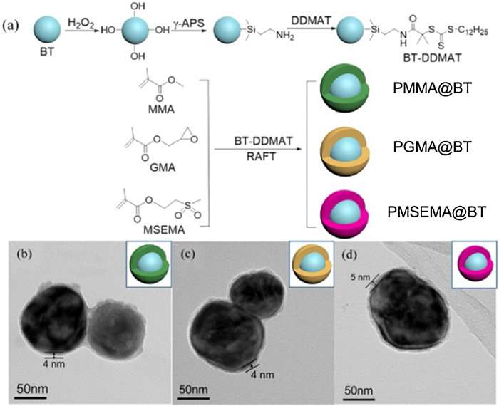
In this work, three core-shell structured BT nanoparticles covered by polymethyl methacrylate (PMMA), polyglycidyl methacrylate (PGMA) and polymethylsulfonyl ethyl methacrylate (PMSEMA) are synthesized via surface-initiated RAFT polymerization, namely PMMA@BT, PGMA@BT and PMSEMA@BT, respectively. Then, these three core-shell nanoparticles are used to prepare nanocomposites with P(VDF-HFP) matrix. The polarity of the three polymers follows the order of PMSEMA (4.3D) > PGMA (2.1D) > PMMA (1.7D) and this work focuses on the role of polymer shell polarity on the dielectric and energy storage performance of the nanocomposites. The preparation procedure of the core-shell nanoparticles mainly includes the synthesis of DDMAT modified BT nanoparticles (BT-DDMAT) and the in-situ initiated RAFT polymerization at the nanoparticle surface, and the details are shown in Fig. 1a.

|
Download:
|
| Fig. 1. (a) The preparation process of three core-shell structured BT nanoparticles. TEM images of (b) PMMA@BT, (c) PGMA@BT and (d) PMSEMA@BT nanoparticles. | |
FT-IR spectra are performed to demonstrate the synthesis of functionalized BT nanoparticles, as shown in Fig. S1a (Supporting information). Compared with the pristine BT nanoparticles, the FT-IR spectrum of BT-DDMAT shows new stretching absorption peaks at 1032 cm−1 (-Si-O-), 1134 cm−1 (-Si-C-), 1448 cm−1 (-N-H-), 1626 cm−1 (-C=O-), and 2800–3000 cm−1 (-CH2, -CH3), indicating that the DDMAT is successfully anchored onto the surface of BT nanoparticles. After RAFT polymerization with different methacrylate-derivative monomers, the FT-IR spectra of the nanoparticles show a stretching absorption peak of ester carbonyl at 1730 cm−1, revealing that polymer shells are successfully formed on the surface of BT-DDMAT. More evidences are verified via 1H NMR spectra, as shown in Figs. S2–S4 (Supporting information).
TGA measurements are carried out to confirm the successful preparation of the three core-shell nanoparticles, as shown in Fig. S1b (Supporting information). The pristine BT and BT-DDMAT have a weight loss of 2.0% and 3.8%, respectively, from room temperature to 800 ℃. By contrast, the core-shell nanoparticles exhibit a much higher loss of weight. For example, the weight loss of PGMA@BT is about 8.0%, also suggesting the successful introduction of polymer shells on the surface of BT-DDMAT.
The microstructure of the core-shell nanoparticles is illustrated by TEM analysis, as shown in Fig. S1c (Supporting information) and Figs. 1b–d. Fig. S1c shows the typical TEM image of a single pristine BT nanoparticle. One can see that it is a typical spherical filler and the surface is free of other materials. However, the TEM images of the three polymer functionalized BT nanoparticles show a core-shell structure with a shell thickness of about 4–5 nm (Figs. 1b–d). This result further confirms that the polymer shells are successfully introduced onto the surface of the BT nanoparticles by RAFT polymerization [27].
Herein, the polymer shell acts as a binder between inorganic fillers and polymer matrix [28], which may alter the crystallization and melting behavior of the P(VDF-HFP) matrix [29]. Fig. S5 (Supporting information) shows the DSC curves of the cooling processes of the pristine P(VDF-HFP) and the nanocomposites and Table S1 provides the detailed data derived from the DSC curves. One can see that the crystallization temperatures (Tc) are increased by about 2–3 ℃ from 122 ℃ of the pure polymer to 124–125 ℃ of the nanocomposites. On the other hand, the nanocomposites exhibit similar melting temperature (Tm) and crystallinity (χc) with the pristine P(VDF-HFP). These data suggest that the core-shell BT nanoparticles act as nucleating agents but also alter the lamella thickness and the crystalline degree of P(VDF-HFP) in the nanocomposites.
Nanoparticles may alter the polymorphs of PVDF-based polymers [30]. Fig. S6 (Supporting information) displays the XRD curves of the pure P(VDF-HFP) and the nanocomposite films. One can see that the XRD patterns of the pure P(VDF-HFP) show diffraction peaks at 17.80°, 18.30°, 19.90° and 26.56°, which correspond to the (010), (020), (110), and (021) reflection of α phase [31]. However, the diffraction peak at 26.56° almost cannot be recognized in the XRD patterns of the nanocomposites, and the diffraction peak at 19.90° shifts to 20.26°, which corresponds to the diffractions at the (110) and (200) planes of β phase P(VDF-HFP). This result demonstrates that the core-shell BT nanoparticles induce the formation of β phase.
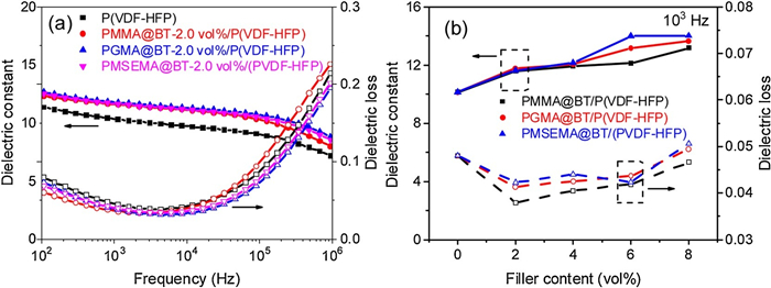
Fig. 2 and Fig. S7 (Supporting information) display the frequency dependent dielectric constant and dielectric loss tangent of the nanocomposites at room temperature. One can see from Figs. S7a–c that the nanocomposites show enhanced dielectric constants when compared with the pristine polymer (about 11 at 100 Hz). For example, the pristine P(VDF-HFP) at 100 Hz, the dielectric constant of the nanocomposites increases to about 15 at 8.0 vol%. However, the dielectric enhancement is not significant because of the low nanoparticle loading, and the nanocomposites almost exhibit comparable dielectric constant at the loading level. This result suggests that the shell polarity shows a marginal effect on the dielectric constant in nanocomposites with low loading.

|
Download:
|
| Fig. 2. (a) Frequency dependence of dielectric constant and dielectric loss of P(VDF-HFP) with 2.0 vol% modified BT nanoparticles. (b) Dielectric constant and dielectric loss of nanocomposites with different volume fractions of modified nanoparticles at 103 Hz. | |
Fig. 2b and Figs. S7d–f display the dielectric loss tangent of the nanocomposites. At low frequency range (Fig. 2b), the dielectric loss of the three nanocomposites first decrease and then increase with the loading of the core-shell BT nanoparticles. Overall, PMMA@BT nanocomposites show lower dielectric loss while dielectric loss of the other two nanocomposites are higher but comparable. Interestingly, at high frequency range, PMMA@BT nanocomposites show a higher dielectric loss in comparison with the pristine P(VDF-HFP) while the other two nanocomposites show lower dielectric loss when compared with the pristine P(VDF-HFP). This phenomenon should be ascribed to different dielectric loss mechanisms. The loss at high frequency (above 105 Hz) mainly originate from the relaxation process of polymer chain segments in the amorphous region [32]. The PGMA@BT and PMSEMA@BT with higher shell polarity may have a stronger interaction with the macromolecular chains of the matrix, which restrains the movement of P(VDF-HFP) segments, resulting in the decreased dielectric loss. At low frequency range, the loss should mainly originate from the leakage current. In this case, the aforementioned dielectric loss results suggest that the PMMA@BT nanocomposites may have lower leakage current density.
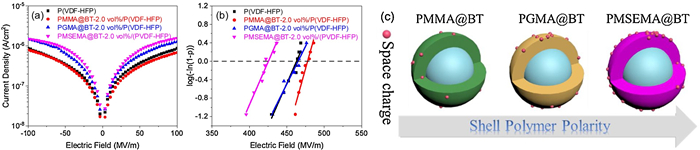
For clarifying the origin of the dielectric loss, leakage current density tests are carried out and the results are shown in Fig. 3a and Figs. S8d–f (Supporting information). In the case of PMMA@BT nanocomposites, as shown in Fig. S8d, the addition of core-shell nanoparticles results in comparable leakage current density with the pristine P(VDF-HFP). However, in the other two types of nanocomposites, the nanocomposites show increased leakage current density with the loading of the core-shell nanoparticles. In addition, the nanocomposites show higher leakage current density in comparison with the pristine P(VDF-HFP) even at low loading.Fig. 3a compared the leakage current results of the three nanocomposites with 2.0 vol% core-shell nanoparticles. One can see that, compared with the pristine P(VDF-HFP), the PMMA@BT nanocomposite shows lower leakage current density while the other two nanocomposites show higher leakage current density. These results are consistent with the lower dielectric loss of PMMA@BT nanocomposites at low frequency range.

|
Download:
|
| Fig. 3. (a) Leakage current density and (b) Weibull breakdown strength plots of the P(VDF-HFP) nanocomposites with 2.0 vol% of PMMA@BT, PGMA@BT and PMSEMA@BT. (c) Schematic illustration for the effect of shell polymer polarity on the space charge capture ability of the core-shell BT nanoparticles. | |
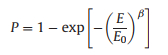
A two-parameter Weibull statistic distribution method is employed to evaluate the breakdown strength (Eb) of the nanocomposites, as shown in Eq. 1 [11]:
|
(1) |
where P is the cumulative probability of electrical failure, β is a parameter related to the dispersion of the data, E is the experiment breakdown strength, and E0 is the characteristic breakdown strength at the cumulative failure probability of 63.2%. The Weibull plots are shown in Fig. 3b and Figs. S8a–c (Supporting information). One can see that the PMMA@BT nanocomposites have higher breakdown strength when compared with the PGMA@BT and PMSEMA@BT nanocomposites at the same loading. Interestingly, at 2.0 vol%, the PMMA@BT nanocomposite exhibits enhanced Eb when compared with the pristine P(VDF-HFP). These results are consistent with the leakage current density of the corresponding nanocomposites. Namely, higher leakage current density results in lower breakdown strength.
Furthermore, the frequency dependence of imaginary modulus M″ of the nanocomposites at varied temperatures is plotted in Fig. S9 (Supporting information). The Arrhenius plot is described by lnfmax versus 1/T as the following equation [33]:
|
(2) |
where fmax is the peak frequency of M″ under a certain T, f0 is the pre-exponential factor, Ea is activation energy (represent the required energy of space charge motion), and k is the Boltzmann constant. The values of Ea of the PMMA@BT, PGMA@BT and PMSEMA@BT are 1.11 eV, 1.14 eV and 1.27 eV at 8.0 vol%, respectively. This indicates that the space charges require more energy to migrate from the interface to other regions in the PMSEMA@BT nanocomposites. In this case, the PMSEMA@BT nanocomposites may have a higher probability of electrical failure because of the space charges accumulation at the interfacial regions (Fig. 3c), which is consistent with the leakage current density results.
D-E loops are measured to evaluate electric polarization and energy storage performance of the nanocomposites, which are shown in Fig. 4 and Fig. S10 (Supporting information). For each nanocomposite, the electrical displacement increases with the nanoparticle loading because BT has a much higher dielectric constant than that of the P(VDF-HFP). In addition, higher shell polarity leads to both higher polarization and remnant polarization (Pr). However, Eb of the nanocomposites becomes lower at high BT loading, and Eb of the nanocomposites with 8.0 vol% decreases to 320–400 MV/m, which is 50–130 MV/m lower than that of the P(VDF-HFP).

|
Download:
|
| Fig. 4. (a) D-E loops and (c) charge-discharge efficiency of the P(VDF-HFP) nanocomposites with 2.0 vol% core-shell nanoparticles. (b) The maximum charge energy density and (d) the maximum discharge energy density of nanocomposite films. | |
Energy densities of the nanocomposites are calculated according to the D-E loops shown in Fig. 4b and Fig. S11 (Supporting information). One can see that at the same loading, the PMMA@BT nanocomposites show higher energy densities when compared with the PGMA@BT and PMSEMA@BT nanocomposites. For instance, at 2.0 vol%, the maximum charge energy density of the PMMA@BT nanocomposite is 12.6 J/cm3, which is higher in comparison with the pristine P(VDF-HFP) (10.7 J/cm3), the PGMA@BT nanocomposite (12.4 J/cm3) and the PMSEMA@BT nanocomposite (10.5 J/cm3). The main reason is that the PMMA@BT nanocomposites show higher Eb than those of the others.
Finally, charge-discharge efficiency (η) of the nanocomposites are shown in Fig. 4c and Figs. S10d–f (Supporting information). Compared with the pristine P(VDF-HFP), the nanocomposites show comparable or slightly higher η at low loading, but have lower η as the loading increases to 8.0 vol%. Among the three nanocomposites, P(VDF-HFP) with 2.0 vol% PMMA@BT has the highest η, which maintains 70% when the electric field is lower than 200 MV/m. However, η decreases with the increases of loading, and becomes < 60% at 8.0 vol%, which is lower than that of the pristine P(VDF-HFP). This phenomenon can be ascribed to the increased Pr, higher dielectric loss and leakage current density. Therefore, it should develop new strategies to suppress these three factors in future work.
In summary, three kinds of core-shell BT nanoparticles are synthesized by surface-initiated RAFT polymerization. The role of the shell polarity in dielectric and energy storage properties of the P(VDF-HFP) nanocomposites is investigated. It is found that space charges tend to accumulate at the shell layer with higher polarity, which may cause a higher probability of electrical breakdown. Accordingly, the nanocomposite with BT covered by the low-polarity shell (i.e., PMMA) exhibits lower dielectric loss, higher breakdown strength, higher discharged energy density and efficiency than the others. These results demonstrate that the coupling interaction between shell and polymer matrix is a key role in improving the energy storage capacity of dielectric nanocomposite nanocomposites, which may guide the future design and fabrication of dielectric nanocomposites.
Declaration of competing interestThe authors declare that they have no known competing financial interests or personal relationships that could have appeared to influence the work reported in this paper.
AcknowledgmentsThe financial support from National Natural Science Foundation of China (No. 51877132) was acknowledged. This work was based on the Thesis of Liwei Wang.
Appendix A. Supplementary dataSupplementary material related to this article can be found, in the online version, at doi:https://doi.org/10.1016/j.cclet.2020.12.032.
| [1] |
W.J. Sarjeant, J. Zirnheld, F.W. MacDougall, IEEE Trans. Plasma Sci. 26 (1998) 1368-1392. DOI:10.1109/27.736020 |
| [2] |
Q. Li, L. Chen, M.R. Gadinski, et al., Nature 523 (2015) 576-579. DOI:10.1038/nature14647 |
| [3] |
H. Pan, Y. Liu, Q. Zhang, et al., Science 365 (2019) 578-582. DOI:10.1126/science.aaw8109 |
| [4] |
B. Chu, X. Zhou, K. Ren, et al., Science 313 (2006) 334-336. DOI:10.1126/science.1127798 |
| [5] |
Z. Dang, J. Yuan, S. Yao, R. Liao, Adv. Mater. 25 (2013) 6334-6365. DOI:10.1002/adma.201301752 |
| [6] |
E. Baer, L. Zhu, Macromolecules 50 (2017) 2239-2256. DOI:10.1021/acs.macromol.6b02669 |
| [7] |
Y. Zhu, Y. Zhu, X. Huang, et al., Adv. Energy Mater. 9 (2019) 1901826. DOI:10.1002/aenm.201901826 |
| [8] |
Q. Chen, Y. Wang, X. Zhou, Q. Zhang, S. Zhang, Appl. Phys. Lett. 92 (2008) 142909. DOI:10.1063/1.2903115 |
| [9] |
T. Huan, S. Boggs, G. Teyssedre, et al., Prog. Mater. Sci. 83 (2016) 236-269. DOI:10.1016/j.pmatsci.2016.05.001 |
| [10] |
Y. Zhu, P. Jiang, Z. Zhang, X. Huang, Chin. Chem. Lett. 28 (2017) 2027-2035. DOI:10.1016/j.cclet.2017.08.053 |
| [11] |
X. Huang, Z. Hu, P. Jiang, IEEE Trans. Dielectr. Electr. Insul. 18 (2011) 375-383. DOI:10.1109/TDEI.2011.5739440 |
| [12] |
X. Huang, B. Sun, Y. Zhu, S. Li, P. Jiang, Prog. Mater. Sci. 100 (2019) 187-225. DOI:10.1016/j.pmatsci.2018.10.003 |
| [13] |
J. Zhu, X. Ji, M. Yin, S. Guo, J. Shen, Compos. Sci. Technol. 144 (2017) 79-88. DOI:10.1016/j.compscitech.2017.03.017 |
| [14] |
X. Huang, P. Jiang, Adv. Mater. 27 (2015) 546-554. DOI:10.1002/adma.201401310 |
| [15] |
Z. Pan, L. Yao, J. Zhai, X. Yao, H. Chen, Adv. Mater. 30 (2018) 1705662. DOI:10.1002/adma.201705662 |
| [16] |
Z. Bao, C. Hou, Z. Shen, et al., Adv. Mater. 32 (2020) 1907227. DOI:10.1002/adma.201907227 |
| [17] |
J. Wang, Z. Shi, F. Mao, S. Chen, X. Wang, ACS Appl. Mater. Inter. 9 (2017) 1793-1800. DOI:10.1021/acsami.6b12786 |
| [18] |
H. Luo, S. Chen, L. Liu, et al., ACS Sustain. Chem. Eng. 7 (2018) 3145-3153. |
| [19] |
Y. Xie, Y. Chen, X. Sun, et al., Chin. Chem. Lett. 32 (2021) 2061-2065. DOI:10.1016/j.cclet.2020.10.001 |
| [20] |
J. Xiong, Z. Li, P. Zhang, et al., Chin. Chem. Lett (2020). DOI:10.1016/j.cclet.2020.10.014 |
| [21] |
Z. Pan, S. Xing, H. Jiang, et al., J. Mater. Chem. A 7 (2019) 15347-15355. DOI:10.1039/C9TA03292D |
| [22] |
K. Yang, X. Huang, Y. Huang, L. Xie, P. Jiang, Chem. Mater. 25 (2013) 2327-2338. DOI:10.1021/cm4010486 |
| [23] |
M. Zheng, Y. Zheng, J. Zha, et al., Nano Energy 48 (2018) 144-151. DOI:10.1016/j.nanoen.2018.03.049 |
| [24] |
W. Xu, G. Yang, L. Jin, et al., ACS Appl. Mater. Inter. 10 (2018) 11233-11241. DOI:10.1021/acsami.8b01129 |
| [25] |
K. Yu, Y. Niu, Y. Zhou, et al., J. Am. Ceram. Soc. 96 (2013) 2519-2524. DOI:10.1111/jace.12338 |
| [26] |
M. Zhu, X. Huang, K. Yang, et al., ACS Appl. Mater. Inter. 6 (2014) 19644-19654. DOI:10.1021/am504428u |
| [27] |
K. Yang, X. Huang, L. Xie, et al., Macromol. Rapid Commun. 33 (2012) 1921-1926. DOI:10.1002/marc.201200361 |
| [28] |
Y. Zhu, P. Jiang, X. Huang, Compos. Sci. Technol. 179 (2019) 115-124. DOI:10.1016/j.compscitech.2019.04.035 |
| [29] |
Y. Song, Y. Shen, H. Liu, et al., J. Mater. Chem. 22 (2012) 8063-8068. DOI:10.1039/c2jm30297g |
| [30] |
V.K. Prateek, Thakur, R.K. Gupta, Chem. Rev. 116 (2016) 4260-4317. DOI:10.1021/acs.chemrev.5b00495 |
| [31] |
K. Shi, B. Sun, X. Huang, P. Jiang, Nano Energy 52 (2018) 153-162. DOI:10.1016/j.nanoen.2018.07.053 |
| [32] |
Y. Wang, M. Yao, R. Ma, et al., J. Mater. Chem. A 8 (2020) 884-917. |
| [33] |
A. Xie, Y. Wang, P. Jiang, S. Li, X. Huang, Compos. Sci. Technol. 154 (2018) 154-164. DOI:10.1016/j.compscitech.2017.11.022 |