 2021, Vol. 32


Supercapacitor (SC) is one promising energy storage device due to its rapid charge/discharge capability, high power density and remarkable cycle stability [1-4]. Nonetheless, the energy density of SC, which is one of the decisive parameters to evaluate the performance of SCs, is too low to meet the growing requirements in various applications. Therefore, improving the energy density of supercapacitor is the key to realize its large-scale practical applications. The energy density of a capacitor can be calculated by E=1/2CV2 [5], where E is the energy density, C is the capacitance, and V is the operation voltage window. It can be seen that the energy density is proportional to the square of the voltage. Therefore, increasing the operating voltage is considered to be an effective strategy in improving the energy density of the device [6, 7]. Electrolyte provides ions that conduct current between two electrodes, and it largely determines the working voltage and the overall performance of the capacitor. Compared with aqueous electrolytes, organic electrolytes tend to have a larger voltage window, but many of them are more expensive, toxic, and flammable [8]. One effective solution to these issues is to develop novel aqueous electrolytes with a high operating voltage for use in SCs. Aqueous electrolytes are advantageous in terms of safety, cost and environmental friendliness. More importantly, the ionic conductivity of aqueous electrolytes is usually much higher than that of organic electrolytes, which leads to better rate performance. Unfortunately, on account of the low decomposition voltage of water (~1.23 V), the ESWs of aqueous electrolytes are much narrower when compared to organic electrolytes, which seriously limits the working voltage of aqueous SCs [9-11].
Highly concentrated aqueous electrolytes, with expanded ESW, have recently gained considerable research interest [12-14]. Wang et al. first proposed a highly concentrated electrolyte with 21 mol/kg lithium bis(trifluoromethanesulfonic) imide (LiTFSI) in an aqueous battery system, and this WIS electrolyte exhibited a wide ESW of 3.0 V (1.9–4.9 V vs. Li+/Li) [14]. In their case, the molar ratio of H2O to Li+ was only 2.6, and part of H2O was surrounded by solvated Li+ sheath containing anion TFSI−. In addition, due to the interaction between excess anions, TFSI− anions can be electrochemically decomposed to form the solid electrolyte interface (SEI) layer which was emphasized as the dominant reason to achieve extended voltage window. Therefore, compared with the traditional dilute aqueous electrolytes, high concentration electrolytes with a WIS configuration can promote the operating voltage. These fluorinated imide-based electrolytes were also used in high voltage sodium ion [15], lithium ion [16] and other aqueous metal ion secondary batteries. Subsequently, our group developed a low-cost and non-toxic potassium acetate (KAc) super concentrated aqueous electrolyte and applied it to high-voltage aqueous symmetric and asymmetric SCs successfully [8, 17]. Cui et al. took advantage of the high solubility of potassium acetate to create the WIS condition in a eutectic mixture of lithium and potassium acetate with water-to-cation ratio as low as 1.3 and achieve an extended ESW while maintaining compatibility with traditional Li-ion battery electrode materials at the same time [18]. So far, there are many reports that the WIS electrolyte can improve the operation voltage of aqueous metal ion batteries [19-22]. In recent years, some researchers also have used hybrid aqueous/non-aqueous electrolytes to further broaden the voltage window of electrolytes [23, 24]. However, the types of WIS electrolyte reported at present are still limited and the application of WIS electrolytes are still rarely used in SCs [25].
In this work, we developed a new WIS electrolyte by dissolving KFSI in water with an ultra-high mass molar concentration of 37 mol/kg regarded as a saturated solution (Fig. S1 in Supporting information), which achieved a wide ESW of 2.8 V and a high conductivity of 23.12 mS/m. Raman spectroscopy and density functional-theory-based molecular dynamics (DFT-MD) simulations verified that in the high concentration KFSI electrolyte, water molecules were strongly coordinated to K+ in the solution to form a stable solvation sheath. As a result, most of the water molecules in the solution are strongly bound and require extra energy to liberate, resulting in a reduced water activity. The electrolyte was successfully applied in carbon-based symmetrical SCs, which achieved ultra-high and stable performance even at a high operation voltage of 2.3 V.
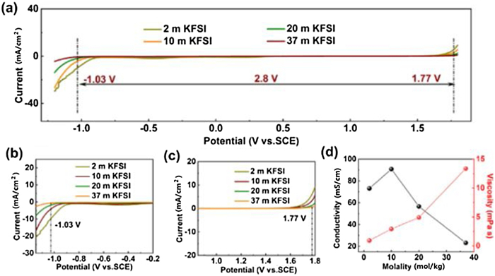
The ESWs of the KFSI electrolytes of different concentrations were determined via linear sweep voltammetry (LSV) tests in a three-electrode system at a scan rate of 10 mV/s (Fig. 1a), and the first cathodic and anodic scans are shown in Figs. 1b and c, respectively. In the three-electrode cells, Pt disc electrode was used as the working and counter electrodes, a saturated calomel electrode (SCE) was used as the reference electrode, and a current density of 0.5 mA/cm2 was selected to define the ESWs of the electrolytes. The ESWs expands as the KFSI concentration increased, and the ESWs of 2, 10, 20 and 37 mol/kg KFSI electrolytes are 2.44, 2.52, 2.66 and 2.8 V, respectively. In the cathodic scan (Fig. 1b), prior to hydrogen evolution reaction (HER), the highly concentrated ions absorbed on the surface of electrode could leads to a passivation process and this passivation eventually suppresses HER [26], pushing its onset potential from -0.83 V (2 mol/kg) to -1.03 V (37 mol/kg). In the anodic scan (Fig. 1c), oxygen evolution reaction (OER) was also suppressed with increase of the salt concentration, which is due to the reduced water activity with coordination to K+ at a high concentration and an increased inner Helmholtz layer populated by FSI anions [27].Fig. 1d summarizes the conductivity and viscosity of KFSI electrolytes with different concentrations at room temperature. It is obvious that the viscosity of the KFSI electrolyte rises slowly as the concentration increases, which is the typical feature of WIS electrolytes because of the strong electrostatic cation-anion attraction [9, 14]. The maximum viscosity is a moderate value of 13.3 mPa s. The conductivities of KFSI electrolytes at 2, 10, 20 and 37 mol/kg are 73.10, 90.82, 56.53 and 23.12 mS/m, respectively. The conductivity of 10 mol/kg KFSI electrolyte is the highest and that of 37 mol/kg KFSI is the lowest. This result could be attributed to the decrease of water content in a high concentration electrolyte causing a low mobility of ions in the solution. Overall, an ESW of ~2.8 V and a high ionic conductivity of 23.12 mS/m were achieved, which will be promising for aqueous SCs to reach a high operating voltage and high rate performance.

|
Download:
|
| Fig. 1. Comparison of physicochemical properties of KFSI-based electrolytes. (a) ESWs of KFSI electrolyte with different concentrations. Magnified view of the regions outlined near (b) cathodic scan and (c) anodic scan. (d) Conductivity and viscosity of different concentrated KFSI electrolytes. m in the figures represents mol/kg. | |
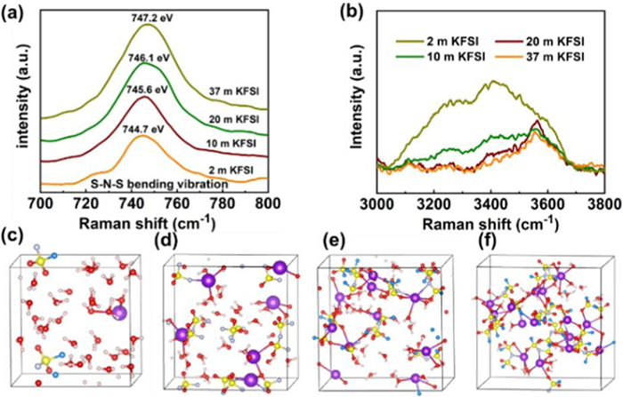
Raman spectroscopies were used to study the S-N-S bending and O–H stretching in KFSI electrolytes with different concentrations. Fig. 2a shows the Raman bands in a range of 700−800 cm−1 that arose from the S-N-S bending vibration of FSI anions. It can be found that with the increase of solution concentration, the (S-N-S) bending vibration from 37 mol/kg KFSI (747.2 cm−1) electrolyte underwent a blue shift compared with that from 2 mol/kg KFSI WIS electrolyte (744.7 cm−1), which should be attributed to the enhanced cation-anion interaction [14, 28]. Fig. 2b shows the stretching vibration of O-H bond in KFSI solutions of different concentrations. In 2 mol/kg KFSI electrolyte, there are a large amount of free water molecules that form clusters through hydrogen bonding, which can be identified by a wide peak at 3000–3800 cm−1 resulting from the stretching vibration between O-H groups. It can be seen that with the increase of the concentration of KFSI, the intensity and width of this peak gradually reduces, which indicates that the number of free water molecules in the solution gradually decreases [29-31].

|
Download:
|
| Fig. 2. Structure characterizations of KFSI electrolytes. (a, b) Raman spectra of the S-N-S bending vibration of FSI− anions, O–H stretching vibration of water molecules. DFT-MD simulations of (c) 2 mol/kg, (d) 10 mol/kg, (e) 20 mol/kg, (f) 37 mol/kg KFSI electrolytes. Atom colors: K, purple; F, blue; S, yellow; N, gray; O, red; H, pink. | |
In order to theoretically understand the internal structure of the solution, first-principles DFT-MD simulation is adopted to model the internal valence bond structure of these four electrolytes. It can be seen from Figs. 2c and d that there is a large amount of free water molecules in the solution with 2 mol/kg KFSI, and the free water molecules form a network structure through hydrogen bonding. With 10 mol/kg KFSI, there are still a lot of free water molecules, but the amount is significantly reduced. As shown in Figs. 2e and f, in high concentration electrolytes, especially in 37 mol/kg KFSI electrolyte, potassium ion is readily coordinated with the oxygen atoms of the water molecules, forming a stable valence bond structure. The hydrogen bond between water molecules is obviously weaken, which is consistent with the relatively lower peak of water observed in Raman spectrum. In addition, due to the low water content, the solvated sheath of unsaturated K+ also forms coordination with some FSI−, resulting in strong interaction [14].
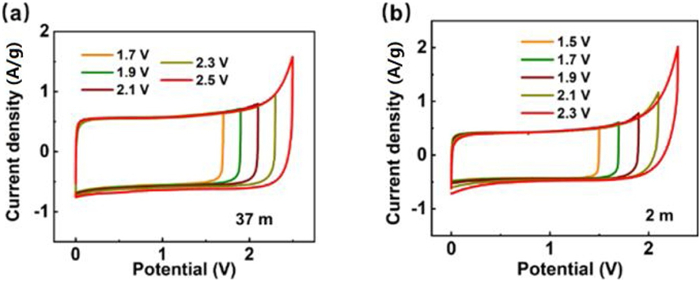
Symmetrical AC//AC SCs were assembled using commercial activated carbon (YP-50F) with different concentrations of KFSI electrolytes, and cyclic voltammetry (CV) were performed to evaluate the maximum operating voltage of SCs. Fig. 3a and b show the CV curves of SCs with 37 mol/kg and 2 mol/kg KFSI electrolytes, respectively. All the curves display a quasi-rectangular shape with slightly symmetric humps at both ends. The only difference is that SCs with 37 mol/kg shows a weak leap until a voltage close to 2.5 V, whereas SCs with 2 mol/kg exhibits a sharp leap at voltage above 2.3 V. The corresponding charge-discharge curves are shown in Fig. S2 (Supporting information). These results demonstrate that the optimal operating voltage of SCs with 37 mol/kg and 2 mol/kg KFSI electrolyte are 2.3 V and 1.9 V, respectively. The oxygen evolution potential was increased by approximately 0.4 V as the KFSI concentration increased from 2 mol/kg to 37 mol/kg, indicating that a high energy density can be achieved. For SCs, other than pursuing a high energy, the self-discharge (SDC) feature is also very critical, which shows the ability of SCs to keep the stored energy on open circuit during an external power shutdown. Fig. S3 (Supporting information) showed the SCs with 37 mol/kg KFSI electrolyte can provide outstanding SDC performance.

|
Download:
|
| Fig. 3. Electrochemical window of AC//AC SCs (SCs). CV curves of the SCs using the (a) 37 mol/kg and (b) 2 mol/kg KFSI electrolytes at different voltage range at a scan rate of 10 mV/s. | |
The electrochemical performance of SCs with 37 mol/kg KFSI electrolyte was tested by cyclic voltammetry and galvanostatic charge-discharge tests within the voltage range of 0–2.3 V. The CV curves of SCs at various scan rates from 10 mV/s to 200 mV/s keep a quasi-rectangular shape, suggesting a typical capacitance behavior (Fig. 4a). Fig. 4b shows the voltage curves at various current densities from 1 A/g to 20 A/g, and the characteristic isosceles triangles agree with CV results. The SCs exhibited an excellent rate performance with capacitance of 96.07, 92.12, 85.50, 76.68 and 61.25 F/g at current densities of 1, 2, 5, 10 and 20 A/g, respectively (Fig. 4c). The specific capacitance tested in full cell is close to in three-electrode system (Fig. S4 in Supporting information). The cycling stability of SCs with 2 and 37 mol/kg KFSI electrolyte at a current density of 1 and 5 A/g are shown in Figs. S5a and b (Supporting information) and Figs. 4d and e, respectively. At the beginning, the decrease of capacity could be ascribed to the irreversible contribution of functional groups on the surface of activated carbon to the capacity. When the reaction of functional groups on the surface of activated carbon is finished, the capacity retention was 90.4% at 1 A/g after 10, 000 cycles and 83.5% at 5 A/g after 50, 000 cycles. Note that, the energy densities of SCs using 37 mol/kg KFSI could reach 20.5 Wh/kg at a power density of 2300 W/kg calculated based on the total mass of the two AC active materials. These results further demonstrate that the excellent electrochemical performance of SCs is ascribed to the highly concentrated KFSI electrolyte. As shown in Fig. 5 and Table S1 (Supporting information) [17, 24, 32-35], the carbon-based SCs using 37 mol/kg KFSI electrolyte showed satisfying electrochemical performance compared with recently published high-performance symmetric supercapacitors using aqueous concentrated electrolytes.

|
Download:
|
| Fig. 4. Electrochemical performance of the SCs with 37 mol/kg KFSI electrolyte. (a) CV curves at different scan rates. (b, c) voltage curves, specific capacitance at different current densities. (d, e) Capacitance retention and Coulombic efficiency at an operation voltage of 2.3 V at a current density of 1 A/g, 5 A/g. | |

|
Download:
|
| Fig. 5. Comparison of operation voltage of SCs using identical AC carbon electrodes and reported electrolytes. | |
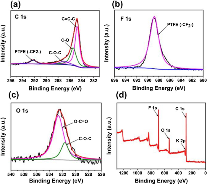
In order to examine the changes of the electrodes after cycling, the chemical composition of the electrode surface was characterized by X-ray photoelectron spectroscopy (XPS). Fig. 6 shows the highly resolution C 1s, F 1s, O 1s and K 2p spectra of the electrode after 100 cycles. The peaks of PTFE(-CF2-) in PTFE were observed at 292.2 eV and 689.2 eV in C 1s and F 1s spectra, respectively. In the core layer spectra of C 1s and O 1s, the peaks at 284.8 eV, 285.7 eV and 288.3 eV are assigned to C–C, C–O and C=O groups, respectively, which are typical signals of carbons and can also be observed in C 1s spectra of the pristine electrode (Fig. S6 in Supporting information). The peaks at 532.7 eV and 531.8 eV corresponding to C–O and C=O groups were observed in the O 1s spectra. The weak K 2p spectrum can be attributed to the unclean electrolyte on the electrode, indicating that after 100 cycles, the potassium element in the electrolyte did not form any compounds attached to the surface of the electrode, which also could be proved by SEM after cycling (Fig. S7 in Supporting information).

|
Download:
|
| Fig. 6. XPS spectra for the electrode surface after cycling. (a) C 1s, (b) F 1s, (c) O 1s, (d) full survey spectra. | |
In summary, we demonstrated a highly concentrated KFSI (37 mol/kg) electrolyte to achieve safe and high voltage SCs. The 37 mol/kg KFSI electrolyte showed a high ESW of 2.8 V with a high ionic conductivity of 23.12 mS/m and a relatively low viscosity of 13.3 mPa s. With this WIS electrolyte, the fabricated SCs displayed a high working voltage of 2.3 V with a high energy density of 20.5 Wh/kg as well as a good capacity retention (83.5% at 5 A/g after 50, 000 cycles). Such a safe KFSI− based WIS electrolyte can be considered as a promising candidate for high voltage aqueous carbon-based SCs and other K-based energy storage devices
Declaration of competing interestThe authors declare that they have no known competing financial interests or personal relationships that could have appeared to influence the work reported in this paper.
AcknowledgmentsThis work was supported by the Shenzhen Science and Technology Innovation Commission (Nos. JCYJ20180504165506495, JCYJ20170818085823773).
Appendix A. Supplementary dataSupplementary material related to this article can be found, in the online version, at doi:https://doi.org/10.1016/j.cclet.2020.12.017.
| [1] |
Z. Yang, J. Ren, Z. Zhang, et al., Chem. Rev. 115 (2015) 5159-5223. DOI:10.1021/cr5006217 |
| [2] |
J. Li, X. Cheng, A. Shashurin, et al., Graphene 1 (2012) 1-13. DOI:10.4236/graphene.2012.11001 |
| [3] |
Y. Wang, Y. Song, Y. Xia, Chem. Soc. Rev. 45 (2016) 5925-5950. DOI:10.1039/C5CS00580A |
| [4] |
S. Zhang, N. Pan, Adv. Energy Mater. 5 (2015) 1-19. DOI:10.1002/aenm.201401401 |
| [5] |
S. Gao, P. Zang, L. Dang, et al., J. Power Sources 304 (2016) 111-118. DOI:10.1016/j.jpowsour.2015.11.028 |
| [6] |
Q. Gou, S. Zhao, J. Wang, et al., Nano-Micro Lett. 12 (2020) 1-22. DOI:10.1007/s40820-019-0337-2 |
| [7] |
J. Wang, Y. Yamada, K. Sodeyama, et al., Nat. Energy 3 (2018) 22-29. DOI:10.1038/s41560-017-0033-8 |
| [8] |
W. Deng, X. Wang, C. Liu, et al., Energy Storage Mater. 20 (2019) 373-379. DOI:10.1016/j.ensm.2018.10.023 |
| [9] |
M. Yu, Y. Lu, H. Zheng, et al., Chem. Eur. J. 24 (2018) 3639-3649. DOI:10.1002/chem.201704420 |
| [10] |
K. Fic, G. Lota, M. Meller, et al., Energy Environ. Sci. 5 (2012) 5842-5850. DOI:10.1039/C1EE02262H |
| [11] |
M. He, K. Fic, E. Frąckowiak, et al., Energy Storage Mater. 5 (2016) 111-115. DOI:10.1016/j.ensm.2016.06.001 |
| [12] |
L. Suo, O. Borodin, Y. Wang, et al., Adv. Energy Mater. 7 (2017) 1701189. DOI:10.1002/aenm.201701189 |
| [13] |
L. Suo, O. Borodin, W. Sun, et al., Angew. Chem. Int. Ed. 55 (2016) 7136-7141. DOI:10.1002/anie.201602397 |
| [14] |
L. Suo, O. Borodin, T. Gao, et al., Science 350 (2015) 938-943. DOI:10.1126/science.aab1595 |
| [15] |
R.S. Kühnel, D. Reber, C. Battaglia, ACS Energy Lett. 2 (2017) 2005-2006. DOI:10.1021/acsenergylett.7b00623 |
| [16] |
C. Yang, J. Chen, T. Qing, et al., Joule 1 (2017) 122-132. DOI:10.1016/j.joule.2017.08.009 |
| [17] |
Z. Tian, W. Deng, X. Wang, et al., Funct. Mater. Lett. 10 (2018) 1-7. |
| [18] |
M.R. Lukatskaya, J.I. Feldblyum, D.G. Mackanic, et al., Energy Environ. Sci. 11 (2018) 2876-2883. DOI:10.1039/C8EE00833G |
| [19] |
Y. Yamada, K. Usui, K. Sodeyama, et al., Nat. Energy 1 (2016) 16129. DOI:10.1038/nenergy.2016.129 |
| [20] |
D.P. Leonard, Z. Wei, G. Chen, et al., ACS Energy Lett. 3 (2018) 373-374. DOI:10.1021/acsenergylett.8b00009 |
| [21] |
L. Chen, J.L. Bao, X. Dong, et al., ACS Energy Lett. 2 (2017) 1115-1121. DOI:10.1021/acsenergylett.7b00040 |
| [22] |
F. Wang, O. Borodin, T. Gao, et al., Nat. Mater. 17 (2018) 543-549. DOI:10.1038/s41563-018-0063-z |
| [23] |
F. Wang, O. Borodin, M.S. Ding, et al., Joule 2 (2018) 927-937. DOI:10.1016/j.joule.2018.02.011 |
| [24] |
W. Wang, W. Deng, X. Wang, et al., Chem. Commun. 56 (2020) 7965-7968. DOI:10.1039/D0CC02040K |
| [25] |
G. Hasegawa, K. Kanamori, T. Kiyomura, et al., Chem. Mater. 28 (2016) 3944-3950. DOI:10.1021/acs.chemmater.6b01261 |
| [26] |
K. Xu, C. Wang, Nat. Energy 1 (2016) 16161. DOI:10.1038/nenergy.2016.161 |
| [27] |
Y. Yamada, J. Wang, S. Ko, et al., Nat. Energy 4 (2019) 269-280. DOI:10.1038/s41560-019-0336-z |
| [28] |
D.M. Seo, O. Borodin, S.D. Han, et al., J. Electrochem. Soc. 161 (2014) A2042-A2053. DOI:10.1149/2.0101414jes |
| [29] |
T.L. Jansen, B.M. Auer, M. Yang, et al., J. Chem. Phys. 132 (2010) 224503. DOI:10.1063/1.3454733 |
| [30] |
N. Yang, C.H. Duong, P.J. Kelleher, et al., Science 364 (2019) 275-278. DOI:10.1126/science.aaw4086 |
| [31] |
R.S. Kühnel, D. Reber, C. Battaglia, J. Electrochem. Soc. 167 (2020) 070544. DOI:10.1149/1945-7111/ab7c6f |
| [32] |
D. Xiao, Q. Wu, X. Liu, et al., ChemElectroChem 6 (2019) 439-443. DOI:10.1002/celc.201801342 |
| [33] |
J. Guo, Y. Ma, K. Zhao, et al., ChemElectroChem 6 (2019) 5433-5438. DOI:10.1002/celc.201901591 |
| [34] |
X. Bu, L. Su, Q. Dou, et al., J. Mater. Chem. A 7 (2019) 7541-7547. DOI:10.1039/C9TA00154A |
| [35] |
Q.Y. Dou, D.W. Wang, H.W. Guo, et al., Energy Environ. Sci. 11 (2018) 3212-3219. DOI:10.1039/C8EE01040D |