 2021, Vol. 32


b Department of Applied Physics, The Hong Kong Polytechnic University, Hong Kong, China
The demand for developing advanced lithium-ion batteries (LIBs) with higher energy density and power density is extremely urgent [1, 2]. The traditional graphite-based anode materials display a low specific capacity of ~350 mAh/g, which cannot satisfy the capacity requirements of high energy-density LIBs [3, 4]. Therefore, probing new active materials with large capacity, high power density, good environmental friendliness and great conductivity to replace graphite has attracted much attention [5, 6].
Transition metal oxides (TMOs), as a typical conversion and/or alloying reaction anode, involve multi-electron reaction during redox [7]. Thereby, TMOs usually deliver theoretical capacities surpassing 1000 mAh/g, which are considered as an expecting group of active material for LIBs [8-10]. In particular, among various TMO anodes, the environmentally friendly and low-cost Fe-based (mixed) oxides have received widespread attention [11, 12]. But, similar to other transition metal oxides (TMOs), Fe-based anode usually suffers from large volume changes and inferior kinetics during redox reactions, resulting in poor cycling stability and rate capability [2, 13]. Previous reports have proved that the rational construction of carbon/oxide composite is an effective way to solve this problem [14, 15]. Carbon matrix not only improves their electron conductivity, but also suppresses their volume expansion effect during charge process [7, 16, 17]. And carbon matrix also reduces the solid electrolyte interface (SEI) and particle agglomeration by decreasing the side reactions on the electrode/electrolyte interface [18-21]. Recently, doping with non-metallic elements (S, N and P) improves the Li storage of the-said TMO anode [22-24]. The phosphide group has independent pairs of electrons in the 3p orbit and empty 3d orbit, which can strengthen the local average density and improve the electron conduction [25, 26]. In addition, the phosphate ion has a longer bond length and a lower electronegativity than O2−. The energy of electron conduction will be reduced by weakening attraction of metal ions to 3d electrons, thereby greatly ameliorating internal reaction and transfer kinetics [27-29].
Previous studies have confirmed that biphasic or multiphasic intergrowth can suppress the growth of primary grains of each phase during solid-state reactions and further reduce size of grains [30]. The reduced size of primary grains can not only facilitate the Li+ diffusion but also increase the active sites of Li+ insertion/extraction [31-34]. In this work, considering the synergetic effects of multiphase composite, carbon matrix and phosphide group, a multiphasic Fe-based anode is rationally designed. The multiphasic nanocomposites are successfully prepared by phosphating and sintering the Fe3O4/C@GO precursors, as shown in Fig. S1 (Supporting information). Thanks to the synergetic effects, the multiphasic Fe-based anode delivers a large specific capacity of 1086 mAh/g, while the initial Coulombic efficiency is as high as 87% at 0.1 C. It also has excellent electrochemical performance, maintaining a specific capacity of ~88% after 300 cycles and a high reversible capacity of 632 mAh/g at 10 C. The proposed multiphasic structure offers a new insight into enhancing the electrochemical property of TMO-based anodes for lithium-ion and other alkali-ion batteries.
The synthesis process of multiphasic nanocomposite is as follows: First, 2.7 g FeCl3·6H2O and 7.2 g sodium acetate were added into 100 mL ethylene glycol, and stir vigorously for 1.5 h. The obtained yellow solution was transferred into Teflon autoclave and further heated at 180 ℃ in an oven for 12 h. Then the Teflon autoclave naturally cooled to room temperature. The formed suspension was centrifuged and the obtained Fe3O4 nanospheres were washed with ethanol and deionized (DI) water. The as-prepared Fe3O4 precursors were dried at 80 ℃ for 12 h under vacuum. 0.05 g Fe3O4 precursors and 0.5 g dextrose are simultaneously dissolved into the mixed solution of 20 mL DI water and 5 mL ethanol. The suspension was added into a 50 mL autoclave and heated at 180 ℃ for 2 h. After that, the suspension was centrifuged and the obtained Fe3O4@C was washed with ethanol and DI water. Finally, the Fe3O4@C precursors were calcined at 500 ℃ for 4 h under argon atmosphere. The Fe3O4@C precursors were subsequently phosphated at 300 ℃ for 2 h, in which the weight ratio of NaH2PO2 and Fe3O4@C reaches 10:1. 80 mg of phosphated Fe3O4@C nanospheres was added into 100 mL DI water, and then subjected to ultrasonic treatment for 2 h. Then 30 mL GO (5 mg/mL) was added into the-said suspension. The suspension was further treated by freeze-drying and then calcined at 600 ℃ for 2 h under argon atmosphere. Finally, the multiphasic nanocomposite was prepared.
Field emission scanning electron microscopes (Hitachis-F20 and Hitachis-SU8010) were used to measure the morphology of as-prepared samples. The transmission electron microscope equipment model was JEM-2010F transmission electron microscope, with built-in X-ray energy spectrometer. The accelerating voltage was 200 kV and the point resolution was 0.25 nm. The elemental species and chemical states of as-prepared samples are assessed by high-resolution X-ray photoelectron spectroscopy (XPS; Thermo ESCALAB250Xi).
The purpose is to further study the cycle performance, rate performance, and practicality of multiphasic nanocomposite (Fe2O3/Fe3O4/Fe3PO7@C@rGO) as anode in LIBs, we assembled the composites into 2032 coin-type half-cells. Negative electrodes composed of 80 wt% active materials, 10 wt% PVDF, and 10 wt% acetylene black are initially prepared. Then the uniformly ball-milled slurry was coated on the Cu foil to be drawn into a thin and uniform film, and dried at 80 ℃ for 6 h. Finally, the dried copper foil loaded with active material was clamped into electrode sheets with a diameter of 1 cm and weighed. The mass loading of electrode is about 1.3 mg/cm2. A button cell battery case is used, in which the microporous polypropylene is used as the diaphragm, and the mixed solution of the concentration of 1 mol/L LiPF6, ethylene carbonate (EC) and diethyl carbonate (DEC) is the electrolyte (the volume ratio is 1:1). The assembly of battery is employed in a glove box protected by high-purity argon, and the water and oxygen content are less than 0.1 ppm. The constant current charging and discharging method is adopted on the battery detection system (Land CT2001A), and the test voltage range is 0−3 V.
XRD is employed to demonstrate the formation of multiphasic composite in the as-prepared sample, as shown in Fig. S2 (Supporting information). The main diffraction peaks of multiphasic composite are marked as (0 1 2), (1 0 4), (1 1 0), (1 1 3), (0 2 4), (1 1 6), (0 1 8), (2 1 4), (3 0 0), (1 0 10) and (2 2 0) planes, which can be assigned to a hexagonal Fe2O3 phase (JCPDS No. 33-0664) with a space group of R-3c. And the residual diffraction peaks can be assigned to the cubic Fe3O4 phase (JCPDS No. 65-3107, Fd-3m space group) and the hexagonal Fe3PO7 phase (JCPDS No. 37-0061, R-3m space group). These clear diffraction peaks suggest the good crystallinity of the Fe-based anode. These XRD results demonstrate that the as-prepared multiphasic composite are composed of Fe2O3, Fe3O4 and Fe3PO7. There is no obvious diffraction peak of graphite, indicating amorphous structure of the carbon and rGO in this composite [35].
SEM images of the as-prepared multiphasic nanocomposite are shown in Fig. S3 (Supporting information). It is clear that the as-prepared multiphasic nanocomposite show a spherical particle with a radius of 100−300 nm. The spherical particles also have a good dispersibility with slight aggregation.
To further investigate the microstructures of multiphasic nanocomposite, TEM measurement is employed, as shown in Fig. 1. The multiphasic nanospheres are anchored on the rGO, as revealed in Figs. 1a and b. The formed rGO frame will provide sufficient volume expansion space for TMO-based active particles through the special characteristics of large specific surface area [36]. In Fig. 1c, the selected area electron diffraction (SAED) pattern shows the polycrystal feature of the nanosphere particle. These results confirm that the spherical particle is assembled by numerous primary grains. HRTEM images (Figs. 1e and f) enlarged from the nanosphere edge in Fig. 4d show that a distinct amorphous carbon layer with a thickness of ~5 nm is formed on the surface of the nanosphere particle. The carbon coating layer serves not only as a conductive matrix for electrons but also as buffer to suppress the volume changes during the charge−discharge. HRTEM images (Figs. 1f and g) show high-order lattice fringes with crystal order spacings of 0.36 nm and 0.29, which correspond to the (012) crystal plane of the main phase Fe2O3 and the (220) crystal plane of Fe3O4, respectively. The elemental mappings of multiphasic composite distinctly illustrated uniform distribution of C, Fe, O and P elements in the polyhedron in Fig. 1h.

|
Download:
|
| Fig. 1. (a, b) TEM image, (c) SAED pattern, (d-g) HRTEM TEM and (h) elemental mapping of multiphasic composite. | |
The surface chemical valence of multiphasic nanocomposite is studied by XPS. According to the XPS spectrum shown in Fig. 2a, only four elements of O, C, Fe and P can be detected in the multiphase composite material, which is identical with the description of the above TEM mapping conclusion. The high-resolution XPS spectrum of P 2p was fitted with two components (Fig. 2b), in which the peaks at 133.2 and 133.3 eV correspond to the binding energy of P 2p3/2 and P 2p1/2 [4, 37]. From the Fe 2p spectrum (Fig. 2c), two distinct Fe 2p3/2 and Fe 2p1/2 characteristic peaks corresponding to Fe3+ can be observed at 711 and 713.5 eV, respectively. The Fe 2p3/2 and Fe 2p1/2 characteristic peaks corresponding to Fe2+ are detected at 724.5 and 726.5 eV [38, 39]. Fig. 2d shows the C 1 s spectrum of the composite material. Four different binding energy peaks were observed at 284.4, 285.6, 288.8 and 291.5 eV, corresponding to sp2 hybridized C atoms and sp3 hybridized C atoms, and the functional groups on the rGO worksheet. It can be clearly seen that the peak intensities of the −C−O, C=O and O−C=O groups are much weaker than those in graphene oxide, indicating the formation of reduced graphene oxide [40].

|
Download:
|
| Fig. 2. XPS spectra of the multiphasic nanocomposite: (a) survey, (b) P 2p, (c) Fe 2p and (d) C 1 s. | |
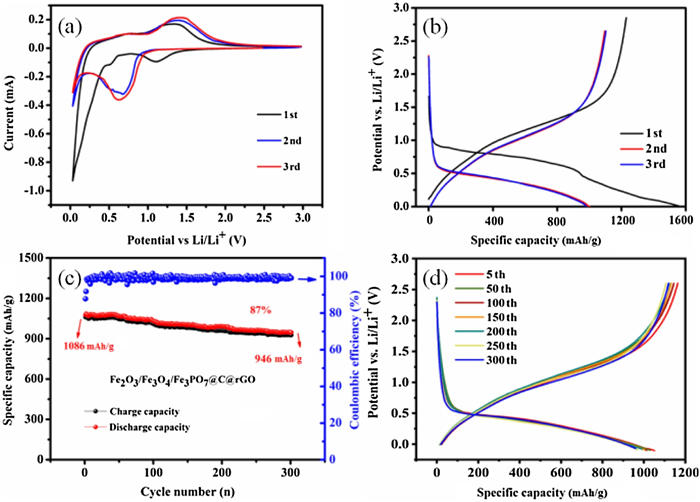
The electrochemical performance of the multiphasic nanocomposite as anode in half cells is studied to confirm the expectedly synergetic effects, as shown in Fig. 3. CV curves of the multiphasic anode between 0 V and 3.0 V are depicted Fig. 3a. The significant difference between the first and other cycles is distinctly found. The sudden reduction peak located at ~0.2 V during the first cycle can be owing to Li+ insertion into Fe2O3 and formation of Li2O. In the subsequent cycles, the reduction peak at ~0.2 V moves to higher voltage of ~0.7 V. The insertion of Li+ into Fe2O3 is achieved in multiple steps and the formula is as follows: [3, 13, 41, 42].

|
(1) |
|
(2) |

|
(3) |

|
(4) |

|
Download:
|
| Fig. 3. Electrochemical performance of the multiphasic nanocomposite as anode in half cells. (a) Representative CV curves at 0.1 mV/s. (b) Selected discharge−charge curves for the initial three cycles. (c) Cycle-life and (d) varied charge/discharge curves from 5th to 100th cycles at 0.1 C and 25 ℃. | |
The initial three charge/discharge profiles of the multiphasic nanocomposite as anode are shown in Fig. 3b, in which the corresponding platforms are consistent with the redox peaks of CV curves in Fig. 3a. The initial discharge of the multiphase nanocomposite is 1192 mAh/g and the first Coulombic efficiency (CE) is 87.7%. The second discharge capacity was 1086 mAh/g, and the Coulombic efficiency increased to 92%. The long-term cycling stability of this multiphasic nanocomposite is also evaluated in Fig. 3c. After 300 cycles at 0.1 C, it still has a specific high capacity of 946 mAh/g, and the retention rate is as high as 87%. And it also has a high average Coulombic efficiency of 99.5%, explaining the superior redox reversibility of the multiphasic nanocomposite. The continuous charge/discharge curves from 5th to 300th cycles are revealed in Fig. 3d. As the charge and discharge cycle increases, the charging platform moves to a higher voltage, and the discharging platform moves to a lower voltage. The rGO frame and the multiphase structure provide the enough space to contain the volume expansion of the Fe-based active particles; thereby the crushing and pulverizing can be effectively suppressed. In addition, the layered porous structure in the three-dimensional graphene framework can provide enough channels to promote the rapid transport of lithium ions and reduce the diffusion limit in the electrode material.
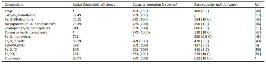
A frame structure built by Fe3PO7 is conducive to the de-intercalation and embedding of sodium ions, so that more electrochemical activity is exposed in the electrolyte [43]. Simultaneously, it will greatly promote the ion mobility of the electrolyte and realize efficient energy storage. The performance comparison between this work and recent reported Fe-based anode is shown in Table 1 [4, 10, 13, 44-51].
|
|
Table 1 A comparison of cycle stability and rate performance of Fe-based materials in a recent report. |
The rate properties of this multiphasic nanocomposite are also measured, as shown in Fig. 4. The composite anode delivers specific capacities of 1086, 1058, 1006, 945, 895, 823, 724, 632 mAh/g as the current densities increase from 0.1 C, 0.2 C, 0.5 C, 1 C, 2 C, 3 C, 5 C to 10 C in Fig. 4a. After the current density recovers to the initial 0.1 C, a high reversibility of 1086 mAh/g is achieved, demonstrating the good structural stability of the multiphasic nanocomposite at high current densities. The Ragone plots for the multiphasic nanocomposite and recently reported Fe-based anodes are illustrated in Fig. 4b. The multiphasic nanocomposite shows much higher specific capacities than these reports when the rates exceed 1 C. It is concluded that the proposed multiphasic nanocomposite in this work shows a better high-rate capability compared with these recent reports. EIS is employed to preliminarily study the reaction kinetics of this multiphasic nanocomposite [52], as shown in Fig. 4c. Table S1 (Supporting information) is the electrochemical parameters simulated according to the equivalent circuit in the illustration, where Rct represents the charge transfer resistance. The multiphasic nanocomposite promotes the formation nano-sized grains, which will shorten the Li+ diffusion path. And the carbon coating will enhance the electronic conductivity during redox ruction. The both improved electron/Li+ conduction contribute to the good reaction kinetics of this multiphasic nanocomposite.

|
Download:
|
| Fig. 4. (a) Rate performance at various current densities from 0.1 C to 10 C. (b) The Ragone plots of this multiphasic nanocomposite and these reported Fe-based anodes. (c) EIS in the frequency range from 0.01 Hz to 100 kHz. | |
In summary, Fe2O3/Fe3O4/Fe3PO7@C@rGO is successfully prepared from Fe3O4/C nanospheres fixed on graphene oxide as precursors. The multiphasic nanocomposite promotes the formation nano-sized grains, which will shorten the Li+ diffusion path. And the carbon coating will enhance the electronic conductivity during redox ruction. Besides, the rGO frame offers the enough space to contain the volume expansion of the TMO-based working particles; thereby the crushing and pulverizing can be effectively suppressed. As a result, the multiphasic composite as anode exhibits outstanding energy storage properties. The proposed multiphasic structure can be expanded to other TMO-based anodes for improving their electrochemical properties.
Declaration of competing interestThe authors declare that they have no known competing financial interests or personal relationships that could have appeared to influence the work reported in this paper.
AcknowledgmentsThis work was supported by the National Natural Science Foundation of China (No. 51672109), the Independent Cultivation Program of Innovation Team of Ji'nan City (No. 2019GXRC011), and Hong Kong Scholars Program (No. XJ2018006). All the authors discussed the results and commented on the manuscript.
Appendix A. Supplementary dataSupplementary material related to this article can be found, in the online version, at doi:https://doi.org/10.1016/j.cclet.2020.12.018.
| [1] |
P.Y. Hou, J.M. Yin, M. Ding, J.Z. Huang, X.J. Xu, Small 13 (2017) 1701802. DOI:10.1002/smll.201701802 |
| [2] |
Y. Dong, Y. Feng, J. Deng, P. He, J. Ma, Chin. Chem. Lett. 31 (2020) 909-914. DOI:10.1016/j.cclet.2019.11.039 |
| [3] |
T. Wang, X. Guo, H. Duan, C. Chen, H. Pang, Chin. Chem. Lett. 31 (2020) 654-666. DOI:10.1016/j.cclet.2019.06.002 |
| [4] |
T.T. Shan, S. Xin, Y.A. You, et al., Angew. Chem. Int. Ed. 55 (2016) 12783-12788. DOI:10.1002/anie.201606870 |
| [5] |
M.Y. Cho, S.B. Yoon, K.B. Kim, D.S. Jung, K.C. Roh, RSC Adv. 6 (2016) 37923-37928. DOI:10.1039/C6RA02205G |
| [6] |
P. Hou, G. Li, X. Gao, J. Mater. Chem. A 4 (2016) 7689-7699. DOI:10.1039/C6TA01878E |
| [7] |
J.M. Jeong, B.G. Choi, S.C. Lee, et al., Adv. Mater. 25 (2013) 6250-6255. DOI:10.1002/adma.201302710 |
| [8] |
H. Kong, C. Lv, C. Yan, G. Chen, Inorg. Chem. 56 (2017) 7642-7649. DOI:10.1021/acs.inorgchem.7b00008 |
| [9] |
H. Li, L.J. Wu, S.G. Zhang, et al., J. Alloys Compd. 832 (2020) 155008. DOI:10.1016/j.jallcom.2020.155008 |
| [10] |
M.V. Reddy, T. Yu, C.H. Sow, et al., Adv. Funct. Mater. 17 (2007) 2792-2799. DOI:10.1002/adfm.200601186 |
| [11] |
B.H. Hou, Y.Y. Wang, .L Q, et al., Adv. Electron. Mater. 5 (2019) 1900006. DOI:10.1002/aelm.201900006 |
| [12] |
G. Wu, N. Liu, X. Gao, et al., Appl. Surf. Sci. 435 (2018) 1329-1336. DOI:10.1016/j.apsusc.2017.11.276 |
| [13] |
G. Li, X. Xu, R. Han, J. Ma, CrystEngComm 18 (2016) 2949-2955. DOI:10.1039/C5CE02408K |
| [14] |
H. Wu, N. Du, J. Wang, H. Zhang, D. Yang, J. Power Sources 246 (2014) 198-203. DOI:10.1016/j.jpowsour.2013.07.063 |
| [15] |
G.T. Xiang, Y. Meng, G.M. Qu, et al., Sci. Bull. 65 (2020) 443-451. DOI:10.1016/j.scib.2020.01.004 |
| [16] |
J. Zhang, T. Huang, Z. Liu, A. Yu, Electrochem. Commun. 29 (2013) 17-20. DOI:10.1016/j.elecom.2013.01.002 |
| [17] |
J. Zhao, Z. Hu, D. Sun, H. Jia, X. Liu, Nanomaterials 9 (2019) 2079-4491. |
| [18] |
Y. Zhang, P. Xin, Q. Yao, J. Alloys Compd. 741 (2018) 404-408. DOI:10.1016/j.jallcom.2018.01.083 |
| [19] |
F. Yang, K. Xu, J. Hu, J. Alloys Compd. 729 (2017) 1172-1176. DOI:10.1016/j.jallcom.2017.09.259 |
| [20] |
J.S. Chen, C.M. Li, W.W. Zhou, et al., Nanoscale 1 (2009) 280-285. DOI:10.1039/b9nr00102f |
| [21] |
C. Shang, X. Zhang, L. Shui, et al., Appl. Surf. Sci. 457 (2018) 804-808. DOI:10.1016/j.apsusc.2018.07.026 |
| [22] |
C. Li, Z. Guo, Y. Pang, et al., ACS Appl. Mater. Inter. 8 (2016) 31638-31645. DOI:10.1021/acsami.6b10115 |
| [23] |
L. Zhou, B. Deng, Z. Jiang, Z.J. Jiang, Chem. Commun. 55 (2019) 525-528. DOI:10.1039/C8CC09140D |
| [24] |
P. Qin, X. Lv, C. Li, Y.Z. Zheng, X. Tao, Sci. Chin. Mater. 62 (2019) 1105-1114. DOI:10.1007/s40843-019-9424-9 |
| [25] |
S. Li, Y. Duan, Y. Teng, N. Fan, Y. Huo, Appl. Surf. Sci. 478 (2019) 247-254. DOI:10.1016/j.apsusc.2019.01.140 |
| [26] |
X. Wang, K. Chen, G. Wang, X. Liu, H. Wang, ACS Nano 11 (2017) 11602-11616. DOI:10.1021/acsnano.7b06625 |
| [27] |
Y. Xiang, Z. Yang, S. Wang, et al., Nanoscale 10 (2018) 18010-18018. DOI:10.1039/C8NR04871A |
| [28] |
Y. Huang, Z. Lin, M. Zheng, et al., J. Power Sources 307 (2016) 649-656. DOI:10.1016/j.jpowsour.2016.01.026 |
| [29] |
Z. Wang, Z. Zhang, J. Xia, et al., J. Alloys Compd. 769 (2018) 969-976. DOI:10.1016/j.jallcom.2018.08.081 |
| [30] |
P.Y. Hou, J.M. Yin, X. Lu, et al., Nanoscale 10 (2018) 6671-6677. DOI:10.1039/C8NR00650D |
| [31] |
J. Liu, X. Xu, R. Hu, L. Yang, M. Zhu, Adv. Energy Mater. 6 (2016) 1614-6832. |
| [32] |
S. Hwang, Q. Meng, P.F. Chen, et al., Angew. Chem. Int. Ed. 56 (2017) 7813-7816. DOI:10.1002/anie.201703168 |
| [33] |
H. Liu, S.H. Luo, D.B. Hu, et al., Appl. Surf. Sci. 495 (2019) 143590. DOI:10.1016/j.apsusc.2019.143590 |
| [34] |
M. Zheng, H. Tang, Q. Hu, et al., Adv. Funct. Mater. 28 (2018) 1707500. DOI:10.1002/adfm.201707500 |
| [35] |
X. Zhang, X. Huang, X. Zhang, et al., Mater. Design 114 (2017) 234-242. DOI:10.1016/j.matdes.2016.11.081 |
| [36] |
S. Wu, G. Fu, W. Lv, et al., Small 14 (2018) 1870020. DOI:10.1002/smll.201870020 |
| [37] |
M. Zhang, J. Yu, T. Ying, et al., J. Alloys Compd. 777 (2019) 860-865. DOI:10.1016/j.jallcom.2018.11.060 |
| [38] |
D.H. Yang, L. Kong, M. Zhong, J. Zhu, X.H. Bu, Small 15 (2019) 1804058. DOI:10.1002/smll.201804058 |
| [39] |
D.H. Yang, L. Kong, M. Zhong, J. Zhu, X.H. Bu, Small 15 (2019) 1970018. DOI:10.1002/smll.201970018 |
| [40] |
M. Liu, Y. Liu, Y. Li, K. Wang, et al., Chem. Eup. J. 25 (2019) 3343-3351. |
| [41] |
Z. Zheng, Y. Zao, Q. Zhang, et al., Chem. Eng. J. 347 (2018) 563-573. DOI:10.1016/j.cej.2018.04.119 |
| [42] |
S.K. Park, G.D. Park, Y.C. Kang, Nanoscale 10 (2018) 11150-11157. DOI:10.1039/C8NR02686F |
| [43] |
J. Huang, Y. Xiong, Z. Peng, et al., ACS Nano 14 (2020) 14201-14211. DOI:10.1021/acsnano.0c07326 |
| [44] |
Q. Zhang, X. Yao, N. Huang, et al., Solid State Ion. 318 (2018) 60-64. DOI:10.1016/j.ssi.2017.09.007 |
| [45] |
J.M. Jeong, B.G. Choi, S.C. Lee, et al., Adv. Mate. 25 (2013) 6250-6255. DOI:10.1002/adma.201302710 |
| [46] |
T. Zhang, C. Zhu, Y. Shi, et al., Mater. Lett. 205 (2017) 10-14. DOI:10.1016/j.matlet.2017.06.020 |
| [47] |
Y. Jin, L. Dang, H. Zhang, et al., Chem. Eng. J. 326 (2017) 292-297. DOI:10.1016/j.cej.2017.05.155 |
| [48] |
V. Ganesan, C.M. Park, ChemistrySelect 4 (2019) 11103-11109. DOI:10.1002/slct.201902598 |
| [49] |
Z. Wang, X. Zhang, Y. Zhao, et al., Nanoscale Res. Lett. 13 (2018) 344. DOI:10.1186/s11671-018-2757-1 |
| [50] |
J. Du, Y. Ding, L. Guo, et al., Appl. Surf. Sci. 425 (2017) 164-169. DOI:10.1016/j.apsusc.2017.06.213 |
| [51] |
Y.S. Hong, Y.J. Park, K.S. Ryu, S.H. Chang, Solid State Ion. 156 (2003) 27-33. DOI:10.1016/S0167-2738(02)00608-2 |
| [52] |
P. Hou, H. Zhang, X. Deng, X. Xu, L. Zhang, ACS Appl. Mater. Interfaces 9 (2017) 29643-29653. DOI:10.1021/acsami.7b05986 |