 2021, Vol. 32


b Key Laboratory for Colloid and Interface Chemistry (Ministry of Education), School of Chemistry and Chemical Engineering, Shandong University, Ji'nan 250061, China;
c School of Physics, Shandong University, Ji'nan 250100, China;
d School of Chemistry and Chemical Engineering, Liao Cheng University, Liaocheng 252059, China
Lithium oxygen batteries (LOBs) with ultrahigh theoretical specific density [1], have been considered as next generation of energy storage devices for future electric vehicles and smart power grids [2]. Further development of LOBs for practical applications, however, is constrained by the sluggish kinetics of the formation decomposition of products (e.g., Li2O2) during oxygen reduction reaction (ORR) and oxygen evolution reaction (OER) processes on the cathode [3]. Moreover, the low electrical conductivity and poor reversibility would result in the passivation of electrodes, which further deprave the cycling stability and rate performance [4]. Therefore, the development of effective cathode catalysts was regarded as a feasible approach to solve these issues through enhancing the kinetics of ORR and OER as well as regulating the morphology of discharge product.
Carbon materials have been extensively studied as catalysts and catalyst supports for LOB cathodes because of their high electrical conductivity, low cost, large specific surface and good ORR electrocatalytic activity [5]. Their OER electrocatalytic properties, however, are normally quite limited. Furthermore, carbon materials as cathode catalysts for LOBs are unstable at a high voltage and prone to react with the electrolytes to generate by-products easily, resulting in the premature failure of the cells [6]. Therefore, the preparation of carbon-based materials with additional active catalysts as the bi-functional cathode catalytic materials is highly demanded.
Palladium (Pd) showed excellent electrocatalytic activities for OER and ORR in LOBs, because Pd could promote the formation of discharge product (e.g., Li2O2) and decrease the overpotentials during charging process, with remarkable material durability account of the great intrinsic activity [7]. In order to optimize their LOB battery performance, numerous efforts have been devoted to constructing Pd-based materials, including alloying [8], compositing [9] and hybridizing [7b, 7c]. It is reported that metal sulfides were widely used in a variety of energy storage devices, owing to their better electrical conductivity compared with their oxide counterparts [10]. Among them, Pd4S has attracted extensively attention of researchers, which can be approximately considered a conductor, as the bonds between Pd atoms were thought to show a primarily metallic character [11]. Du et al. reported a series of palladium sulfides, including Pd4S, PdS, and Pd16S7 showing good catalytic activities for ORR due to the optimized oxygen-binding ability introduced by the existence of effective oxygen absorption sites on the surfaces [12].
In this work, Pd/Pd4S heterostructures were successfully in-situ deposited on the surfaces of HCS as cathode catalysts for LOBs. The composite catalysts with large specific surface area and hierarchical porous structure could not only facilitate electrolyte immersion and mass transport to boost electrocatalytic reactions, but also offer sufficient space for storing the discharge products to improve cycling stability. Notably, the heterostructure consisting of Pd and Pd4S nanoparticles as highly catalytic active sites could significantly promote the kinetics of ORR and OER. Thus, the Pd/Pd4S@HCS cathode exhibited large specific capacities with high battery efficiency, favorable rate performance and stable reversibility for LOBs. The excellent electrocatalytic performance demonstrates that the Pd/Pd4S@HCS can be used as efficient bi-functional cathode catalysts for LOBs and exhibit great prospects for potential applications in energy-related devices.
The synthetic procedure for Pd/Pd4S@HCS was shown in Scheme 1. The X-ray diffraction (XRD) measurements were used to verify the crystalline structure of the as-prepared samples. Fig. S1a (Supporting information) shows a broad peak centered at around 23° in the XRD pattern of HCS, suggesting its graphitic structure. Except for the similar graphitic peak, the XRD pattern of Pd/Pd4S@HCS clearly pictures obvious diffraction peaks of Pd (PDF#88-2335) and Pd4S (PDF#73-1387), the peaks of Pd clearly shown in the profile of Pd@HCS, indicating that they were successfully decorated on the HCS architecture. D and G band of the samples can be obtained in the Raman spectra, as shown in Fig. S1b (Supporting information), and the degrees of graphitization can be estimated from the intensity ratio of D and G band (ID/IG). After loaded with Pd and Pd4S nanoparticles, the value of ID/IG of Pd/Pd4S@HCS (0.803) became higher than that of HCS (0.787), which demonstrates that the disorder degree of the carbon matrix experienced an increase. It is well-known that nanoparticles on the carbon matrix as defect sites can normally decrease the degree of graphitization [7a, 13], and the greater ID/IG thus reveals that more defects were introduced by the nanoparticles on the carbon matrix.

|
Download:
|
| Scheme1. Schematic illustration of synthetic procedure for Pd/Pd4S@HCS. | |
The N2 adsorption/desorption isotherm was used to characterize the specific surface and pore size distribution of the samples, and both of them show mesoporous characteristics with the marked type V isotherm with H3-type hysteresis loop, as depicted in Figs. S1c and f (Supporting information). Specifically, the pore size distributions of HCS and Pd/Pd4S@HCS concentrated at 7.26 and 6.52 nm according to BJH method, and their specific surface areas are 147.8 and 124.49 m2/g by BET model, respectively, which mainly originated from the loading of Pd and Pd4S nanoparticles on the carbon matrix for the composite. The mesoporous structure and the large specific surface area can provide more space for exposing active sites and promote mass transport, which could significantly enhance the electrochemical performance of LOBs. The X-ray photoelectron spectroscopy (XPS) spectra were collected and analyzed to investigate the surface electronic state and elemental composition of Pd/Pd4S@HCS. The XPS survey spectrum in Fig. S1d (Supporting information) suggests the existence of elements of Pd, S, C and O in the composite. As for the high-resolution spectrum of Pd 3d in Fig. S1e (Supporting information), it can be concluded that Pd features two types of valence state. The strong peaks located at 335.6 and 340.9 eV can be indexed as the signals of Pd0, and the weak peaks at 336.3 and 341.5 eV can be assigned to the signals of Pd2+, respectively [14]. The content of Pd/Pd4S on the hollow hierarchical porous carbon spheres was determined by the thermogravimetric analysis (TGA) result, as shown in Fig. S2 (Supporting information). The main weight losses of HCS and Pd/Pd4S@HCS at around 500 ℃ were caused by carbon oxidation. The tiny residue of HCS might be the incomplete corrosion of silica. A small weight increase at 270 ℃ for Pd/Pd4S@HCS is ascribed to the oxidation of Pd, and it is followed by a weight loss, which is due to the decomposition of palladium oxide [7a]. Therefore, the contents of Pd/Pd4S heterostructure in the composite could be calculated to be 13.0%.
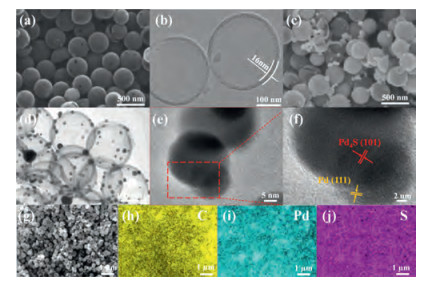
As pictured in Fig. S3 (Supporting information), the precursor appears to be uniformly spherical morphology. After annealing treatment, this structure remained for the HCS in Fig. 1a, and TEM image in Fig. 1b illustrates that HCS exhibit a hollow structure with hierarchical pores on their surfaces, consistent with the result of N2 adsorption/desorption data. The shell of each hollow sphere is about 16 nm, and the diameter of the hollow cavity is around 260 nm. After decorated with Pd/Pd4S nanoparticles, it can be seen that there are several nanoparticles randomly decorating on the hollow shells (Figs. 1c and d) without any agglomerations. The element mapping results of Pd/Pd4S@HCS in Figs. 1g–j reveal that C, Pd and S elements are uniformly distributed in the composite, showing good dispersity of the Pd/Pd4S nanoparticles on HCS. The images of HRTEM were shown in Figs. 1e and f, the lattice spacing of 0.38 nm and 0.23 nm could attribute to (101) and (111) planes of Pd4S and Pd, respectively, revealing the unique heterostructure between Pd4S and Pd.

|
Download:
|
| Fig. 1. (a) SEM and (b) TEM images of HCS; (c) SEM, (d) TEM, (e, f) HRTEM and (g-j) element mapping images of Pd/Pd4S@HCS. | |
RDE technique was performed to investigate the ORR electrocatalytic activities of those samples in oxygen-saturated 0.1 mol/L KOH at a spinning speed of 1600 rpm. It can be seen in the LSV data in Fig. 2a that the Pd/Pd4S@HCS electrode exhibits the lowest half-wave potential (E1/2) of -0.218V (vs. AgCl/Ag) with the largest limited diffusion current density, while the HCS and super P electrodes can only exert E1/2 of -0.289 and -0.361V, respectively. This demonstrates that the Pd/Pd4S@HCS displays the highest ORR electrocatalytic activity among them. The electrocatalytic activities were also detected by the CV testing between 2.35V and 4.35V vs. Li+Li at a scan rate of 0.15 mV/s in LOBs. The CV plots in Fig. 2b shows that the Pd/Pd4S@HCS cathode could deliver higher reduction and oxidation peak currents, which manifests its stronger catalytic activities of ORR and OER for LOBs, compared with the Pd@HCS and HCS counterpart. The initial galvanostatic discharge-charge curves of Pd/Pd4S@HCS and HCS cathodes are shown in Fig. 2c. It is noted that the Pd/Pd4S@HCS cathode can deliver a specific capacity of 19540 mAh/g at a current density of 100 mA/g when discharged to 2.35V. However, the HCS and Pd@HCS cathodes can only exhibit 3993 and 5957 mAh/g. Furthermore, the LOB cell with Pd/Pd4S@HCS cathode can deliver a specific capacity of 19540 mAh/g when recharged to 4.33V, which is much larger than those using the HCS and Pd@HCS cathode 408 and 4677 mAh/g). The pure carbon paper was also tested (Fig. S7 in Supporting information) at a current density of 100 mA/g as the cathode, and the data indicates that it shows limited discharge and charge specific capacities. More importantly, the overpotentials of the Pd/Pd4S@HCS cathode are remarkably lower than those of the HCS and Pd@HCS cathode, suggesting its superior electrocatalytic efficiency.

|
Download:
|
| Fig. 2. (a) LSV curves for ORR of Super P, HCS and Pd/Pd4S@HCS. (b) CV curves and (c) first discharge/charge curves of HCS, Pd@HCS and Pd/Pd4S@HCS cathodes. (d) The discharge/charge profiles of Pd/Pd4S@HCS cathode at various current densities ranging from 100 mA/g to 500 mA/g with a limited capacity of 500 mAh/g. (e) Selected discharge/charge profiles and (f) cycling performance of Pd/Pd4S@HCS cathode under a capacity limit of 600 mAh/g at 100 mA/g. | |
Rate capability was conducted under the fixed capacity of 500 mAh/g and 1000 mAh/g at different current densities. The discharge and charge terminal voltages of Pd/Pd4S@HCS cathode exhibit a slight increase with the increase of current densities, as shown in Fig. 2d, suggesting its excellent rate performance. Moreover, it displays great reversibility that the discharge and charge terminal voltages could nearly recover to those of the first cycle. Specifically, corresponding discharge and charge terminal voltages in Fig. S5a (Supporting information) show only an increase and decrease of 0.23 and 0.05V, respectively, when the current densities increase from 100 mA/g to 500 mA/g. As the current density decrease back to 100 mA/g, the difference of charge terminal voltage between the first cycle and last cycle is only 0.09V as discharge terminal voltage without a change. Even the limited specific capacity increase to 1000 mAh/g, shown in Figs. S4 and S5b (Supporting information), the overpotentials just experienced a little increase, while the difference of terminal voltage between lowest and highest is 0.34V and 0.07V for charge and discharge process. The continuously cycled galvanostatic discharge/recharge patterns in Fig. 2f display the terminal voltages with limited specific capacity of 600 mAh/g at 100 mA/g. The Pd/Pd4S@HCS cathode exhibits a fabulous cycling performance of more than 90 cycles without an obvious increase of terminal voltages. Its selected discharge and recharge curves are listed in Fig. 2e to further investigate the corresponding electrochemical processes. In contrast, the HCS cathode can only survive to 13 cycles, and its terminal discharge terminal voltages dramatic decrease below 2V. Those results demonstrate great cycling stability of Pd/Pd4S@HCS cathode. To further explore the cycling performance of Pd/Pd4S@HCS cathode, the Nyquist plots are collected and shown in Fig. S9 (Supporting information). The diameter of the semicircle typically represents the charge transfer resistance, and the diameter exhibits a great increase after first discharging, indicating the formation of insulating discharge product Li2O2. After recharging, the diameter decreases sharply, suggesting the Li2O2 decomposed. After 90 cycles, the diameter shows a slight increase than that of the first cycle, which may be caused by the tiny accumulation of by-products.
To obtain further insight into the discharge and charge processes that occurred in LOBs, the morphologies and crystalline characteristics of cathodes at different states were intensively examined. After full discharging, three new peaks located at 32.9°, 35.0° and 58.7° can be clearly observed in the XRD pattern of the Pd/Pd 4S@HCS cathode in Fig. S10d (Supporting information), respectively according to the (100), (101) and (110) planes of Li2O2 (PDF#209-0355), and these three peaks disappeared after recharging. This implies that the main discharging product is Li2O2, which can be totally decomposed in the charge process. The in-situ differential electrochemical mass spectrometry (DEMS) was conducted to further investigate the charge product, and the DEMS curve (Fig. S11 in Supporting information) shows that O2 was main evolved gas during charging, which implies that Li2O2 → O2 conversion is the dominating reaction in the charging process. Nevertheless, there are also little amount of CO2 generated at the end of charging process, and this is because inevitable by-product could be decomposed at higher charging voltage [15]. The Raman spectrum of Pd/Pd4S@HCS cathode at different stages are shown in Fig. S12 (Supporting information). After discharging to 1000 mAh/g, both the main discharging product (Li2O2) and intermediate (LiO2) can be observed in the spectrum (Fig. S12a). The peak at 830 cm−1 could be associated with the Li2O2, the peak at 1123 and 1505 cm-1 are related to LiO2-like compound and the strong interaction between LiO2 and graphitic carbon surface, respectively. [16] The absence of peaks after recharged suggests the efficient catalytic activity. The SEM images of the Pd/Pd4S@HCS cathodes at different states are shown in Figs. S10a–c. It is demonstrated that the discharge product Li2O2 in the form of toroid shape were imbedded in this cathode after initial discharging, while the discharge product grown in the HCS cathode shows a dense film-like structure in the Fig. S7. After the recharge process, the discharged product cannot be observed in the Pd/Pd4S@HCS cathode, which means that the Li2O2 had totally decomposed account of its fabulous catalytic activity. This result is consistent with the information from XRD patterns. Furthermore, the Pd/Pd4S@HCS can completely maintain its characteristic morphology with the limited accumulation of by-products, which demonstrate its material durability during cycling. For the HCS, there are amounts of accumulation of by-products after ten cycles, which finally results in the death of cells with HCS cathode. Therefore, it is concluded that the Pd/Pd4S heterostructure could provide fabulous superior catalytic activities for boosting discharge and charge processes to obtain long cycling life and large specific capacities.
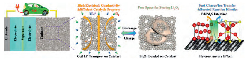
The schematic illustration of the formation and decomposition of the Li2O2 discharge product in the cathode material is shown in Fig. 3. The special hierarchical porous structure with larger specific surface area can not only expose more active sites on the catalytic material, but also provide the free spaces for oxygen diffusion and ion transport, aiding in realizing the full potential of Pd/Pd4S heterostructure [7a, 12]. Pd and Pd4S nanoparticles show great catalytic activities for advancing OER and ORR during cycling, and the interfacial effect of Pd/Pd4S heterostructure could enable fast charge and ion transport, which could further boost electrocatalytic efficiency. Particularly, the Li2O2 discharge product of different cathodes presents different morphology, which could largely affect the electrocatalytic performance of the LOBs [17]. The formation of discharge product Li2O2 has been proved caused by disproportionation reaction of intermediate LiO2, the electrochemical growth route has two mechanisms as the surface-adsorption pathway and the solvation-mediated pathway and is given by the following reactions [18]:

|

|
where * means a surface absorbed species, and sol and S indicate their solution and S forms. The film-like Li2O2 usually is related to surface-adsorption pathway and generally means low discharge and charge specific capacity, as formed in the HCS cathodes, because the dense insulating Li2O2 can hinder the transfer of ions, charge and oxygen. On the contrary, the Li2O2 generated in the Pd/Pd4S@HCS cathodes shows toroid-shaped morphology, which is associated with solvation-mediated pathway and usually considered to be helpful for achieving high battery performance [19]. The interfacial effect of heterostructure could boost the transport of ions and charge, Pd4S nanoparticles could absorb more oxygen and intermediates on the surface and Pd with its inherent catalytic activity could boost the weak dynamic processes. Both of them can promote a right shift of equilibrium [20], and the toroid plates formed and turned into toroid-shaped Li2O2. All those factors contribute to the high cycling stability, favorable rate performance and large specific capacities with low overpotentials of LOBs decorated with Pd/Pd4S@HCS cathodes.

|
Download:
|
| Fig. 3. Illustration for the reaction mechanism of formation and decomposition of the Li2O2. | |
In summary, Pd/Pd4S@HCS was successfully synthesized via the in-situ deposition of Pd/Pd4S heterostructure on hollow carbon spheres, which exhibited excellent electrocatalytic activities. Typically, the unique hollow hierarchical structure with a large specific surface area and high electrical conductivity can provide enough spaces for oxygen transport and loading active sites, as well as storing discharge products in the composite. As a result, LOBs with Pd/Pd4S@HCS cathode deliver superior specific capacities of 19540 mAh/g at a current density of 100 mA/g, favorable rate performance and satisfying cycling stability of 90 cycles with a fixed specific capacity of 600 mAh/g at a current density of 100 mA/g. All those results indicate that the Pd/Pd4S@HCS are potentially efficient cathode materials for LOBs.
Declaration of competing interestThe authors report no declarations of interest.
AcknowledgmentsThe research was supported by the Taishan Scholars Programme of Shandong Province (No. tsqn20161004), Project for Scientific Research Innovation Team of Young Scholar in Colleges and Universities of Shandong Province (No. 2019KJC025), Young Scholars Program of Shandong University (No. 2019WLJH21) and China Postdoctoral Science Foundation (No. 2020M672054)
Appendix A. Supplementary dataSupplementary material related to this article can be found, in the online version, at doi:https://doi.org/10.1016/j.cclet.2020.11.003.
| [1] |
(a) P.G. Bruce, S.A. Freunberger, L.J. Hardwick, J.M. Tarascon, Nat. Mater. 11 (2012) 19-29; (b) W. Chen, Y.F. Gong, J.H. Liu, Chin. Chem. Lett. 28 (2017) 709-718. |
| [2] |
(a) A.C. Luntz, B.D. McCloskey, Chem. Rev. 114 (2014) 11721-11750; (b) T. Ogasawara, A. Débart, M. Holzapfel, P. Novák, P.G. Bruce, J. Am. Chem. Soc. 128 (2006) 1390-1393; (c) C.L.M. Wu, C.B. Liao, L. Li, J. Yang, Chin. Chem. Lett. 27 (2016) 1485-1489. |
| [3] |
(a) H.D. Lim, B. Lee, Y. Bae, et al., Chem. Soc. Rev. 46 (2017) 2873-2888; (b) B. Liu, Y.L. Sun, L. Liu, S. Xu, X.B. Yan, Adv. Funct. Mater. 28 (2018)1704973. |
| [4] |
(a) X.D. Lin, R.M. Yuan, S.R. Cai, et al., Adv. Energy Mater. 8 (2018) 1800089; (b) C. Zhu, Y. Wang, L. Shuai, et al., Chin. Chem. Lett. 31 (2020) 1997-2002. |
| [5] |
(a) S.M. Xu, X. Liang, Z.C. Ren, K.X. Wang, J.S. Chen, Angew. Chem. Int. Ed. 57 (2018) 6825-6829; (b) Y. Lin, B. Moitoso, C. Martinez-Martinez, et al., Nano Lett. 17 (2017) 3252-3260; (c) Y.J. Wang, H.B. Fan, A. Ignaszak, et al., Chem. Eng. J. 348 (2018) 416-437; (d) Z.W. Chang, J.J. Xu, X.B. Zhang, Adv. Energy Mater. 7 (2017) 1700875; (e) H. Liu, X.X. Liu, W. Li, et al., Adv. Energy Mater. 7 (2017) 1700283. |
| [6] |
(a) M.M.O. Thotiyl, S.A. Freunberger, Z.Q. Peng, P.G. Bruce, J. Am. Chem. Soc. 135 (2013) 494-500; (b) B.D. McCloskey, A. Speidel, R. Scheffler, et al., J. Phys. Chem. Lett. 3 (2012)997-1001. |
| [7] |
(a) J. Wang, L.L. Liu, S.L. Chou, H.K. Liu, J.Z. Wang, J. Mater. Chem. A 5 (2017) 1462-1471; (b) X.Y. Lu, Y. Yin, L. Zhang, et al., Nano Energy 30 (2016) 69-76; (c) X.Y. Lu, J.W. Deng, W.P. Si, et al., Adv. Sci. 2 (2015) 1500113. |
| [8] |
(a) W.B. Luo, X.W. Gao, S.L. Chou, J.Z. Wang, H.K. Liu, Adv. Mater. 27 (2015) 6862-6869; (b) B.K. Ko, M.K. Kim, S.H. Kim, et al., J. Mol. Catal. A: Chem. 379 (2013) 9-14. |
| [9] |
(a) F.L. Meng, Z.W. Chang, J.J. Xu, X.B. Zhang, J.M. Yan, Mater. Horiz. 5 (2018) 298-302; (b) L.M. Leng, X.Y. Zeng, H.Y. Song, et al., J. Mater. Chem. A 3 (2015) 15626-15632. |
| [10] |
(a) J. Jiang, Y.Y. Li, J.P. Liu, et al., Adv. Mater. 24 (2012) 5166-5180; (b) X.H. Rui, H.T. Tan, Q.Y. Yan, Nanoscale 6 (2014) 9889-9924; (c) Y.C. Liu, Y. Li, H.Y. Kang, T. Jin, L.F. Jiao, Mater. Horiz. 3 (2016) 402-421. |
| [11] |
R. Gronvoled, R. Rost, Acta Crystallogr. 15 (1962) 11-13. DOI:10.1107/S0365110X62000031 |
| [12] |
C. Du, P. Li, F.L. Yang, et al., ACS Appl. Mater. Interfaces 10 (2018) 753-761. DOI:10.1021/acsami.7b16359 |
| [13] |
J.R. Shen, H.T. Wu, W. Sun, et al., J. Mater. Chem. A 7 (2019) 10662-10671. DOI:10.1039/C9TA00543A |
| [14] |
L.L. Long, A.Y. Zhang, Y.X. Huang, X. Zhang, H.Q. Yu, J. Mater. Chem. A 3 (2015) 4301-4306. DOI:10.1039/C4TA05818F |
| [15] |
(a) P. Wang, Y.Y. Ren, R.T. Wang, et al., Nat. Commun. 11 (2020) 1576; (b) B. He, J. Wang, J.Q. Liu, et al., Adv. Energy Mater. 10 (2020) 1904262. |
| [16] |
(a) M.W. Yuan, C.Y. Nan, Y. Yang, et al., ACS Omega 2 (2017) 4269-4277; (b) M.W. Yuan, S.T. Zhang, L. Liu, et al., ACS Sustain. Chem. Eng. 7 (2019) 17464-17473; (c) M.W. Yuan, R. Wang, W.B. Fu, et al., ACS Appl. Mater. Interfaces 11 (2019) 11403-11413. |
| [17] |
R.R. Mitchell, B.M. Gallant, Y. Shao-Horn, C.V. Thompson, J. Phys. Chem. Lett. 4 (2013) 1060-1064. DOI:10.1021/jz4003586 |
| [18] |
(a) J.S. Hummelshoj, A.C. Luntz, J.K. Norskov, J. Chem. Phys. 138 (2013) 034703; (b) Z.Y. Lyu, Y. Zhou, W.R. Dai, et al., Chem. Soc. Rev. 46 (2017) 6046-6072; (c) A.J. Hu, W.Q. Lv, T.Y. Lei, et al., ACS Nano 14 (2020) 3490-3499. |
| [19] |
N.B. Aetukuri, B.D. McCloskey, J.M. Garcia, et al., Nat. Chem. 7 (2015) 50-56. DOI:10.1038/nchem.2132 |
| [20] |
Q.S. Huang, F. Dang, H.T. Zhu, et al., J. Power Sources 451 (2020) 50-56. |