 2021, Vol. 32


b School of Environment and Energy, South China University of Technology, Guangzhou 510006, China;
c Guangxi Key Laboratory of Theory and Technology for Environmental Pollution Control, Guilin University of Technology, Guilin 541004, China;
d State Key Laboratory of Multi-Phase Complex Systems, Institute of Process Engineering, Chinese Academy of Sciences, Beijing 100190, China
In recent decades, nanoalloy materials have drawn increasing attention due to their novel functionalities and potential applications in various catalysis fields, such as methanol oxidation [1, 2], CO2 reduction [3], VOCs oxidation [4]. Nanoalloys are prepared by fusing two or more metallic elements, but their characters/properties are distinctly different from single-counterpart nanoparticles. Along with promising progress on micro-structural characterizations, researchers have demonstrated that nanoalloy materials can achieve superior catalytic performances, owing to the combination of abundant active sites, and effectively optimizing the electronic structures among neighboring elements [5]. Several strategies have been proposed to reinforce desirable activity, such as controlling the well-defined sizes/shapes, and tailoring the surface atomic arrangement and different composition of nanoparticles (NPs) [5-7].
CO oxidation as a probe reaction has been widely studied in heterogeneous catalysis [8, 9], and CO can also cause the fatal health impacts and the poisoning for exhaust gas catalysts at low temperature. Various catalysts such as noble metals (Pt, Pd, Au, Ir, Ag, etc.) and transition-metal (Mn-, Co-, Cu-, Ni-, Ti-, etc.) oxides (TMOs) have been developed for CO oxidation [10-15]. Single Pt catalysts exhibit inferior catalytic activity at low temperature range, due to the strong adsorption of CO molecules to Pt that hinders O2 adsorption on Pt sites [7]. Some studies have suggested that Ag could effectively activate O2 species but adsorb fewer CO molecules [15, 16]. Combining bimetallic Pt-Ag alloy would be a potential way to prepare an excellent catalyst with superior activity for CO oxidation. Some strategies such as co-impregnation, co-deposition-precipitation and NaBH4 methods have been extensively used to synthesize bimetallic Pt-Ag catalysts [15, 17], but are not easy to synthesize size-controllable nanoparticles. Furthermore, manganese oxide (MnO2) has also been extensively used in pollutants removal due to the excellent oxygen storage capacities (OSC), plentiful valence states and structural flexibility [18-20]. However, how to use the advantages of both PtAg alloys and MnO2 special structures to improve the catalytic performances for CO oxidation?
Herein, for the first time, we explore an unusual strategy for constructing Pt-Ag alloys with unique sizes from 3.3 nm to 5.8 nm onto a MnO2 microsphere to synthesize efficient catalysts via a two-step method combining glycol reduction and electrostatic chemical adsorption. Impressively, the as-synthesized PtAg-alloyed/MnO2 catalysts exhibited excellent properties for CO oxidation. The physico-chemical property of catalysts was further characterized by a series of ex-situ characterization techniques, such as X-ray powder diffraction (XRD), scanning electron microscopy (SEM), transmission electron microscope (TEM), hydrogen temperature programmed reduction (H2-TPR) and oxygen temperature programmed desorption (O2-TPD), etc. Quasi in-situ XPS was carried out to confirm the reconstitution of gas-phase O2 molecules at oxygen vacancy sites.
To study the growth process, bimetallic PtAg-alloyed nanoparticles (NPs) at different stages were characterized by TEM. TEM and high-resolution transmission electron microscopy (HRTEM) images of bimetallic PtAg-x (x representing the reduction time) NPs with different size distribution are showed in Fig. 1. These PtAg-x alloy NPs have a narrow size distribution in parent solutions, and the average sizes change obviously with the increase of reduction time from 0.5 h to 2.5 h. The average sizes of alloy NPs can be measured to be about 3.3±0.2, 3.7±0.2, 4.6±0.3, 5.3±0.3 and 5.8±0.3 nm, respectively. HRTEM images reveal that the lattice fringe in these PtAg alloys is calculated to be about 0.233 nm, which is assigned to the (111) plane of PtAg NPs.

|
Download:
|
| Fig. 1. TEM and HRTEM images of PtAg-x nanoalloys in different states: (a, b) 0.5 h, (c, d) 1.0 h, (e, f) 1.5 h, (g, h) 2.0 h and (i, j) 2.5 h. | |
The sphere-like shape of MnO2 is composed of the aggregation of multitudinous nanocubes, as shown in Fig. 2a. TEM observation (Fig. 2b) is also consistent with the uniform microsphere over PtAg-1.0/MnO2 with an average diameter of around 1.45 μm, in which PtAg alloy are immobilized onto the surface of MnO2 microspheres (Fig. 2c). As shown in the HRTEM image, the two lattice spacings are 0.233 and 0.241 nm, which are indexed as the (111) and (400) planes of PtAg alloy and γ-MnO2, respectively. Additionally, elemental mapping further evidences the homogeneous distribution of Pt and Ag elements, indicating the formation of PtAgalloyed architectures with a molar ratio of Pt: Ag (2.16:1), as shown in Figs. 2d-h. Typical X-ray diffraction patterns of MnO2 microsphere and PtAg NPs are showed in Fig. 2i. The diffraction peaks at 2θ=34.1°, 37.8°, 42.9° and 55.3° are ascribed to the (301), (400), (202) and (402) planes of γ-MnO2 (JCPDS No. 42-1316) [21]. All the diffraction peaks of PtAg NPs situate at the middle of diffraction peaks between pure Pt (JCPDS No. 04-0802) and Ag (JCPDS No. 04-0783) phase, further suggesting the generation of PtAgalloyed structures [22].

|
Download:
|
| Fig. 2. (a) SEM image of MnO2, (b, c) TEM images, (d-g) high-angle annular dark-field scanning transmission election microscope (HAADF-STEM) element mappings and (h) Scanning and transmission analytical electron microscopy (STEM-EDX) spectrum of PtAg-1.0/MnO2, and (i) XRD patterns of MnO2 and PtAg alloys. | |
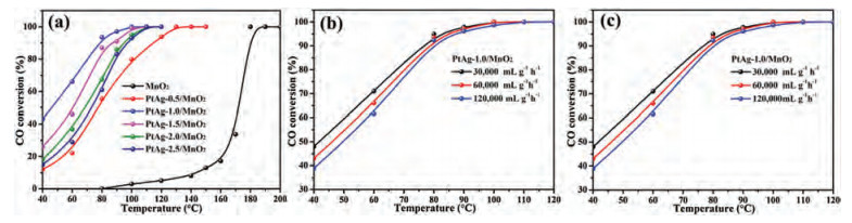
The catalytic activity of MnO2-based catalysts was evaluated for CO oxidation under the reaction condition of 1.0 vol% CO, 20 vol% O2 and weight hourly space velocity (WHSV) 60, 000 mL g−1h−1. As shown in Fig. 3a, for the CO conversion, T10, T50 and T99 (the temperature of 10%, 50% and 99% CO conversion, respectively) for pure MnO2 nanospheres are 140 ℃, 175 ℃ and 180 ℃, respectively. Obviously, the introduction of PtAg alloys promotes the catalytic activity over MnO2 nanospheres due to a strong interaction between PtAg NPs and MnO2 support. The T50 behavior for CO oxidation over the MnO2-based catalysts decreases in the sequence of PtAg-1.0/MnO2 > PtAg-1.5/MnO2 > PtAg-2.0/MnO2 > PtAg-2.5/MnO2 > PtAg-0.5/MnO2 > MnO2. A tendency of catalytic activity on the PtAg-supported catalysts exhibits a volcanic type, as shown in Fig. S1 (Supporting information). In detail, the T50 and T99 values of PtAg-0.5/MnO2 are 77 ℃ and 110 ℃, which reduce 98 ℃ and 70 ℃ than those of pure MnO2, respectively. It is conspicuous that PtAg-1.0/MnO2 exhibits a highest catalytic activity for CO oxidation among these catalysts, achieving the 50% and 99% CO conversion at about 45 ℃ and 100 ℃, respectively.

|
Download:
|
| Fig. 3. (a) CO conversion over MnO2-based catalysts vs. reaction temperature, the effect of (b) CO concentration and (c) WHSV on the catalytic activity of PtAg-1.0/MnO2. | |
The effect of CO concentration and WHSV on the catalytic activity over PtAg-1.0/MnO2 were further checked, as shown in Figs. 3b and c. With the scale-down of CO concentration, the catalytic activity of CO oxidation is increased slightly in PtAg-1.0/MnO2. In addition, the catalytic activity is also less affected by WHSV, their complete CO conversion at different WHSV is achieved at 100 ℃. The stability of PtAg-1.0/MnO2 was also carried out by a long-term test at 40 ℃ and 80 ℃, as shown in Fig. S2 (Supporting information). At lower reaction temperature (40 ℃), the catalytic activity of CO oxidation over PtAg-1.0/MnO2 drastically reduces from 48.6% to 39.2% within 24 h. When the temperature increased to 80 ℃, the CO conversion still remained above 94% after testing for 24 h, implying an excellent stability of PtAg-1.0/MnO2 catalyst at higher conversions.
Table S1 (Supporting information) shows the specific surface area data of MnO2-based catalysts, and it can be observed that the as-synthesized nanomaterials with mesoporous structures have larger surface areas from 92.7 m2/g to 105.5 m2/g and uniform pore diameter distributions from 6.4 nm to 9.5 nm (Fig. S3 in Supporting information). After immobilized PtAg alloys onto MnO2 microsphere, the surface areas and pore volumes of PtAg-x/MnO2 are reduced due to surface PtAg NPs blocking the pore structure of MnO2 microsphere.
To further substantiate the influence of PtAg NPs on the chemical characteristics of MnO2 microsphere, a series of ex-situ characterization techniques were used to detect the surface element composition and low-temperature reducibility of catalysts. Fig. S4 (Supporting information) shows the Mn 2p XPS spectra of all the MnO2-based materials. The binding energies (BEs) of Mn2p3/2 could be divided into two main peaks due to the formation of Mn4+ and Mn3+. Note that the BEs centered at 640.5 eV and 641.5 eV are assigned to the Mn3+ and Mn4+ cations, respectively [23]. It can be seen that the surface element compositions of MnO2 are changed obviously after immobilizing PtAg alloys onto MnO2 sphere, compared to MnO2 sphere. The average oxidation state (AOS) of Mn ions could be calculated by the BEs of Mn 3s XPS spectra (Fig. S5 in Supporting information) [24]. The Mn4+/Mn3+ molar ratios and AOS are summarized in Table S2 (Supporting information). The Mn4+/Mn3+ molar ratios and AOS of these PtAg-alloyed catalysts are significantly improved due to the presence of additional electrons of PtAg NPs close to the oxygen vacancies of MnO2. The O 1s XPS spectra of MnO2-based materials are divided into three main peaks (Fig. S6 in Supporting information), which are ascribed to lattice oxygen (Olatt), surface adsorbed oxygen (Oads) and adsorbed hydroxyl/water molecules (OOH), respectively [25]. Based on the fitting results, it could be found that these catalysts immobilized PtAg alloys maintain the higher Olatt/Ototal ratios at around 0.65, in comparison to the MnO2 support. Besides, the Pt 4f and Ag 3d XPS spectra of MnO2-based materials have no obvious changes, as shown in Fig. S7 (Supporting information).
The hydrogen temperature programmed reduction (H2-TPR) analysis (Fig. S8 in Supporting information) reveals that the reduction process mainly presents three stepwise reduction peaks for MnO2 sphere in the whole range from 100 ℃ to 400 ℃, possibly attributed to the reduction of adsorbed oxygen species, MnO2 to Mn3O4, and then to MnO [26, 27]. For the PtAg-supported materials, as can be seen, a new reduction peak appears at approximately 105 ℃, the modification with PtAg alloys also leads to shift of other two reduction peaks at about 253 ℃ and 362 ℃ to lower temperature regions and slightly enhances the reduction of adsorbed oxygen species, indicating that the reducibility of these samples increases. The new reduction peak is ascribed to the interaction between PtAg NPs and MnO2 deriving from the spillover of hydrogen from PtAg atoms to MnO2 [18]. In addition, PtAg-1.0/MnO2 exhibits the maximum intensity of H2 consumption peak at 105 ℃, compared to other PtAg-supported materials. The interaction results in a preeminent low-temperature reducibility and a promoted oxygen mobility.
The oxygen temperature programmed desorption (O2-TPD) analysis (Fig. S9 in Supporting information) further confirms that the immobilization of PtAg alloys onto MnO2 microspheres could effectively improve the bond strength of oxygen species of catalysts. The desorption regions occurring at 80–150, 150–300 and 300−550 ℃ are mainly ascribed to the desorption of physically adsorbed oxygen (O2 or O2−), chemisorbed oxygen (O− or O22−) and bulk lattice oxygen (O2−) species, respectively [28, 29]. Obviously, in comparison to the MnO2 support, PtAg-supported catalysts exhibit a larger amount of physically adsorbed oxygen and chemical adsorbed oxygen as active oxygen species that could participate effectively in the CO reaction, and also promote the release of bulk lattice oxygen more readily. Among these PtAg-alloyed catalysts, the PtAg-1.0/MnO2 has the largest amount of chemical adsorbed oxygen species. This above result provides a favorable evidence to corroborate the effect of PtAg alloys addition on O2 activation.
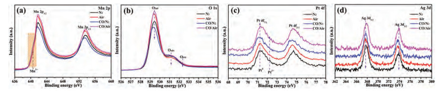
To gain the surface-specific information of PtAg-1.0/MnO2 catalyst in the reaction process, quasi in-situ XPS measurement was further carried out at 120 ℃ with different atmosphere. All spectra were calibrated based on the C 1s region at 284.6 eV (Fig. S10a in Supporting information). It could be seen that changing the reaction atmosphere leads to the changes of surface composition (Mn4+, Olatt and Pt0), but the Ag region is no significant change, as shown in Fig. 4. The change of Mn oxidation state (AOS) over PtAg-1.0/MnO2 catalyst can be confirmed by the BEs of Mn 3s XPS spectra, as shown in Fig. S10b (Supporting information). Quasi in-situ XPS spectra confirms that the Mn4+/Mn3+ and Olatt/Ototal molar ratios at air pretreatment are higher than those of at N2 pretreatment (Fig. 4, Fig. S11 and Table S3 in Supporting information), in which the surface Pt0 species can be reoxidized to Pt2+ (Fig. S11b in Supporting information) in the presence of O2, due to the top surface Mn3+ layers of MnO2 oxidizing to Mn4+, and the replenishment of Olatt from gas-phase O2. Under 1.0 vol% CO/N2 condition, the surface Mn3+ and Pt0 species of catalyst appears increased, while the amount of Olatt decreases to 0.728 (Table S3), indicating that the lattice oxygen species act as active oxygen to participate in the CO reaction. Upon switching to 1.0 vol% CO/Air condition, the surface oxidation state of PtAg-1.0/MnO2 catalyst do not important change compared to that in the air condition. Some researchers have speculated that Mars-van Krevelen (MvK) and Langmuir–Hinshelwood (L-H) mechanism could occur simultaneously in the CO oxidation over certain catalysts [18, 30]. Combining information from quasi in-situ XPS results reveal that both Mn and Pt ions on the catalyst surface realize alternating reduction-oxidation by CO and O2 molecules. CO fast adsorbed onto metal sites reacts with neighboring lattice oxygen species, in which the oxygen vacancy sites are replenished and excited by gas-phase O2, meanwhile, also facilitate some adsorbed oxygen species to participate in the CO oxidation.

|
Download:
|
| Fig. 4. Quasi in-situ (a) Mn 2p, (b) O 1s, (c) Pt 4f and (d) Ag 3d XPS spectra of PtAg-1.0/MnO2 catalyst at 120 ℃ with different atmosphere (N2, Air, 1.0 vol% CO/N2 and 1.0 vol% CO/Air). | |
In summary, we have successfully synthesized a series of bimetallic PtAg alloys with uniform size distribution from about 3.3–5.8 nm, which were immobilized onto MnO2 microspheres assembled by nanocubes to generate novel PtAg-alloyed/MnO2 catalysts. These PtAg NPs addition remarkably enhanced the catalytic activity for CO oxidation over the MnO2 microspheres. Furthermore, PtAg-1.0/MnO2 catalyst exhibited a highest activity achieving complete CO oxidation at 100 ℃. Experimental studies revealed that immobilizing PtAg NPs onto MnO2 supports to form an interface can greatly facilitate both adsorbed-oxygen capacities and O2-activation abilities, and better low-temperature reducibility. Quasi in-situ XPS results confirmed that the lattice oxygen species as dominating active oxygen took part in the CO oxidation process, which are replenished at oxygen vacancy sites by gas-phase O2. Hence, this work has well implications for the understanding on the roles of PtAg alloys and oxygen utilization.
Declaration of competing interestThe authors report no declarations of interest.
AcknowledgmentsThis research described above was financially supported by the Research Funds of the Guilin University of Technology (No. GUTQDJJ202041), Guangxi Key Laboratory of Theory and Technology for Environmental Pollution Control (No. Guikeneng 2001K002), National Natural Science Foundation of China (Nos. 51978189, 51878292), National Key R & D Program of China (No. 2017YFC0211503) and China Postdoctoral Science Foundation (No. 2020M683629XB).
Appendix A. Supplementary dataSupplementary material related to this article can be found, in the online version, at doi:https://doi.org/10.1016/j.cclet.2020.11.062.
| [1] |
A.B. Yousaf, M. Imran, A. Zeb, T. Wen, et al., Electrochim. Acta 197 (2016) 117-125. DOI:10.1016/j.electacta.2016.03.067 |
| [2] |
P. Yang, X. Yuan, H. Hu, et al., Adv. Funct. Mater. 28 (2018) 1704774. DOI:10.1002/adfm.201704774 |
| [3] |
J. He, N.J.J. Johnson, A. Huang, C.P. Berlinguette, ChemSusChem 11 (2018) 48-57. DOI:10.1002/cssc.201701825 |
| [4] |
Y. Wang, C. Dai, B. Chen, et al., Catal. Today 258 (2015) 616-626. DOI:10.1016/j.cattod.2015.03.042 |
| [5] |
H. Fang, J. Yang, M. Wen, Q. Wu, Adv. Mater. 30 (2018) 1705698. DOI:10.1002/adma.201705698 |
| [6] |
N. Wang, Y. Xu, Y. Han, C. Gao, X. Cao, Nano Energy 17 (2015) 111-119. DOI:10.1016/j.nanoen.2015.07.015 |
| [7] |
S.Y. Hwang, C. Zhang, E. Yurchekfrodl, Z. Peng, J. Phys. Chem. C 118 (2014) 28739-28745. DOI:10.1021/jp5101768 |
| [8] |
Y. Fang, X. Gong, Chin. Chem. Lett. 30 (2019) 1346-1350. DOI:10.1016/j.cclet.2018.12.025 |
| [9] |
M. Waqas, P.M. Kouotou, A. El Kasmi, Y. Wang, Z.Y. Tian, Chin. Chem. Lett. 31 (2020) 1201-1206. DOI:10.1016/j.cclet.2019.06.042 |
| [10] |
Y. Yan, H. Li, Z. Lu, et al., Chin. Chem. Lett. 30 (2019) 1153-1156. DOI:10.1016/j.cclet.2019.03.030 |
| [11] |
F. Kettemann, S. Witte, A. Birnbaum, et al., ACS Catal. 7 (2017) 8247-8254. DOI:10.1021/acscatal.7b02646 |
| [12] |
Y.X. Zhao, M.M. Wang, Y. Zhang, X.L. Ding, S.G. He, Angew. Chem. Int. Ed. 58 (2019) 8002-8006. DOI:10.1002/anie.201902008 |
| [13] |
Y. Chen, J. Chen, W. Qu, et al., Chem. Commun. 54 (2018) 10140-10143. DOI:10.1039/C8CC04935A |
| [14] |
J. Ohyama, T. Koketsu, Y. Yamamoto, S. Arai, A. Satsuma, Chem. Commun. 51 (2015) 15823-15826. DOI:10.1039/C5CC05484B |
| [15] |
A. Sandoval, A. Aguilar, C. Louis, A. Traverse, R. Zanella, J. Catal. 281 (2011) 40-49. DOI:10.1016/j.jcat.2011.04.003 |
| [16] |
A. Wang, J. Liu, S. Lin, T. Lin, C. Mou, J. Catal. 233 (2005) 186-197. DOI:10.1016/j.jcat.2005.04.028 |
| [17] |
X. Cao, N. Wang, Y. Han, et al., Nano Energy 12 (2015) 105-114. DOI:10.1016/j.nanoen.2014.12.020 |
| [18] |
N. Zhang, L. Li, R. Wu, et al., Catal. Sci. Technol. 9 (2019) 347-354. DOI:10.1039/C8CY01879K |
| [19] |
Y. Wang, D. Yang, S. Li, et al., Chem. Eng. J. 357 (2019) 258-268. DOI:10.1016/j.cej.2018.09.156 |
| [20] |
S. Mo, Q. Zhang, J. Li, et al., Appl. Catal. B: Environ. 264 (2020) 118464. DOI:10.1016/j.apcatb.2019.118464 |
| [21] |
J. Jia, P. Zhang, L. Chen, Appl. Catal. B: Environ. 189 (2016) 210-218. DOI:10.1016/j.apcatb.2016.02.055 |
| [22] |
Z. Li, Y. Li, C. He, P.K. Shen, J. Mater. Chem. A 5 (2017) 23158-23169. DOI:10.1039/C7TA07525A |
| [23] |
W. Tang, X. Wu, D. Li, et al., J. Mater. Chem. A 2 (2014) 2544-2554. DOI:10.1039/C3TA13847J |
| [24] |
B. Zhang, G. Cheng, W. Ye, et al., Dalton Trans. 45 (2016) 18851-18858. DOI:10.1039/C6DT03523J |
| [25] |
D. Jampaiah, V.K. Velisoju, P. Venkataswamy, et al., ACS Appl. Mater. Interfaces 9 (2017) 32652-32666. DOI:10.1021/acsami.7b07656 |
| [26] |
J. Zhang, Y. Li, L. Wang, C. Zhang, H. He, Catal. Sci. Technol. 5 (2015) 2305-2313. DOI:10.1039/C4CY01461H |
| [27] |
S. Rong, P. Zhang, F. Liu, Y. Yang, ACS Catal. 8 (2018) 3435-3446. DOI:10.1021/acscatal.8b00456 |
| [28] |
Y. Wang, H. Arandiyan, Y. Liu, et al., ChemCatChem 10 (2018) 3429-3434. DOI:10.1002/cctc.201800598 |
| [29] |
B. Li, Q. Yang, Y. Peng, et al., Chem. Eng. J. 366 (2019) 92-99. DOI:10.1016/j.cej.2019.01.139 |
| [30] |
L. Lukashuk, N. Yigit, R. Rameshan, et al., ACS Catal. 8 (2018) 8630-8641. DOI:10.1021/acscatal.8b01237 |