 2021, Vol. 32


b Institute of Energy, Hefei Comprehensive National Science Center, Hefei 230026, China;
c School of Materials Science and Engineering, Nanjing University of Science and Technology, Nanjing 210094, China;
d School of Chemical Engineering and Technology, Xi'an Jiaotong University, Xi'an 710049, China
As the consumption of traditional fossil fuels increases year by year, and environmental problems becomes increasingly serious, it is a challenging task to find new, clean, sustainable, and renewable energy sources to meet the current demands. Due to its high energy density, widely available and feasible transport of the liquid fuel, direct methanol fuel cell (DMFC) stands out from many fuel cells and become one of the most promising fuel cells [1-6]. Meanwhile, the methanol oxidation reaction (MOR) is a basic anode reaction of DMFCs and the preparation of efficient MOR electrocatalyst remains as an urgent problem in this field [7-12].
Pt nanomaterials have received considerable attention because of their superior catalytic nature in MOR [7, 13-17]. Increasing efforts have been devoted to improving the catalytic activity by atom-precise controlled synthesis of Pt catalysts with tailored morphologies [14, 17-20]. However, their application is still limited because of the low abundance and high prices of Pt. The design of core-shell nanostructure catalysts with a shell of Pt or Pt alloy is an effective way to reduce Pt content and retain its high activity [21-26]. One facile approach of constructing a Pt monolayer (PtML) on a second metal substrate (such as Pd, Au and Ir) is via under-potential deposition (UPD) of Cu monolayer (CuML) followed by galvanic replacement with Pt [27-33]. By controlling the amount of charge and deposition voltage in UPD, the coverage of Pt or Ru can be controlled in sub-monolayer (Pts-ML/Rux-ML) precision. Meanwhile, the activity of PtML electrocatalysts is also dependent on the substrate metal [28, 34, 35]. The catalytic activity of the surface sites can be modified by manipulation of the local chemical environment through the ligand effect and strain effect [36, 37]. For instance, the activity of Pt can be enhanced by tensile strain as in PtML on Au (111) and reduced by compressive strain as in PtML on Pd (111) [31]. The CO poisoning of catalyst surface is another issue in MOR as Pt is easily poisoned by the reaction intermediate of adsorbed CO (COads) from dissociation of methanol molecules to form Pt-COads during the electrocatalytic reaction. CO can only be oxidized to CO2 at a larger overpotential [36]. According to the research on platinum-based catalysts in methanol oxidation electrocatalysis, Pt-Ru bimetallic nanomaterials have been widely recognized as the best CO-tolerant electrocatalysts [38-43]. According to Watanabe-Motoo bifunctional mechanism, adding an oxophilic metal such as Ru to Pt provides adsorbed hydroxyl groups (OHads) at a lower potential, which acts as an oxidant to oxidize COads on Pt surface to CO2, thereby improving the activity of methanol oxidation [36]. A synthetic protocol combining facile preparation of substrate nanostructure with high surface area, and utilization of the bifunctional effect is still missing [44, 45].
In this work, we report the Au@Pts-ML@Rux-ML core-shell nanowires (NWs) with ultralow content of Pt and Ru as a superior MOR electrocatalyst. Au NWs with a diameter of 6.8 nm and Boerdijk-Coxeter helix structure is used as the substrate, which features a low-temperature fast preparation, high surface ratio and well-defined (111) facets [46-48]. Au NWs are selected as the substrate because of the high ratio of surface atoms and one-dimensional electron pathway [44, 46, 47]. The surface coating is realized by successive UPD of Cu on the Au NWs with high aspect ratio followed by galvanic replacement by Pt and Ru while different coverage of Pt and Ru can be controlled by the amount of deposited Cu. The introduction of Ru to surface Pt further boosts the performance of the bimetallic core-shell structure as compared to the pure Pt monolayer on Au NWs. A volcano plot was derived correlating the Ru coverage and the electrocatalytic performance in MOR. Long-term stability of the most optimum catalyst of Au@PtML@RuML is also demonstrated. Our results provide a fast but effective method to maximize the precious metals in atomic precision and provide a novel and reasonable way to design MOR electrocatalysts with enhanced activity and durability.
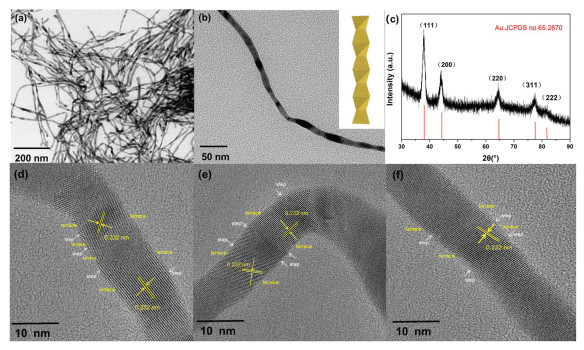
It is acknowledged that one-dimensional Au NWs with high aspect ratio can provide the large surface area, low Ostwald ripening and fast electron communication [42, 44]. In this work, the Au NWs were synthesized in a quick protocol and chosen as substrate to construct Au@Pt core-shell NWs. We demonstrate a rapid and feasible fabrication of Au NWs with high aspect ratio (~6.8 nm) and yield (approximately 100%). Fig. 1 shows the characterization of the Au NWs obtained after the reduction of HAuCl4 for 1min at 60 ℃. From the transmission electron microscopy (TEM) image in Fig. 1a, the obtained product is uniform NWs with high aspect ratio, i.e. length of up to several hundreds of nanometers and average diameter of 6.8 nm. The observed dark contrast in Fig. 1b may be caused by the stronger diffraction of the constituent tetrahedral which are oriented close to specific low-index directions. Like the previous report, the Au NWs adopt a Boerdijk-Coxeter (BC) type helix structure (inset of Fig. 1b) and predominantly expose {111} facets [41]. The HRTEM image (Figs. 1d-f) clearly reveals the dominant {111} facets on the surface of the Au nanowires which are further decorated with rich steps. The measured lattice spacings of ~0.232 nm can be assigned to the {111} planes of Au with face-centered cubic (fcc) structure. Furthermore, the varied {111} orientations indicate a possible Boerdijk-Coxeter (BC) type helix structure (Fig. 1b) composed of stacked tetrahedra with twisted orientations. Multiple domains can be identified from the NWs with different orientations, which contributes to the blurred lattice image in the HRTEM image. The X-ray diffraction (XRD) pattern (Fig. 1c) of the NWs exhibits a set of diffraction peaks corresponding to fcc Au.

|
Download:
|
| Fig. 1. The characterization of the Au wires with high aspect ratio. (a) Low- and (b) high magnification TEM images of the Au NWs. The inset of (b) shows a model illustration of the Boerdijk-Coxeter type helical nanowire. (c) XRD pattern of the Au NWs. (d) HRTEM images of an individual Au nanowire. | |
To obtain Au@Pts-ML with different Pt coverage, Cu was deposited on the Au NWs with controlled coverage via UPD. The UPD deposition of monatomic layer of Cu has been well-developed on single crystalline Au(111) surfaces, but has been rarely observed experimentally on the surface of Au NWs. Fig. 2a shows the cyclic voltammogram (CV) of the Au NWs in N2-saturated 0.5 mol/L H2SO4 and 0.5 mol/L H2SO4 containing 5 mmol/L CuSO4 electrolyte. The reduction peak of Au oxide is constantly located at 1.13 V vs. RHE in both cases. Two additional pairs of redox peaks can be identified from the red curve (between 0.2 V and 0.6 V) before the bulk deposition of Cu, which are attributed to the Cu UPD features at Au (111) surfaces. They were ascribed to two different deposition structures including coadsorption of Cu and sulfate anion followed by a complete Cu adlayer deposition. The electrochemical surface area (ECSA) of the as-synthesized Au NWs catalyst was calculated from the charge associated with the Cu UPD peaks. Assuming a charge constant of 420 μC/cm2, the ECSA of the Au NWs was estimated to be around 0.24 cm2. NWs of Au@Cus-ML with different Cu coverage (0.25, 0.5, 0.75 and 1.0 ML) can be obtained by negative linear scanning voltammetry from 0.9 V to different termination potentials (Fig. 2b). The TEM image of the Au@CuML in Fig. S1a (Supporting information) shows similar smooth surface and segmented contrast as the initial Au NWs (Fig. 1a), indicating an ideal CuML structure without obvious island formation.

|
Download:
|
| Fig. 2. The model and the characterization of Au@Pts-ML and Au@PtML@Rux-ML. (a) A model illustration of Pt and Ru deposition on the Boerdijk-Coxeter type helical Au nanowire. (b) Cu UPD on the AuNW/CNT in N2-saturated H2SO4 + 5 mmol/L CuSO4 solution, the inset four arrows illustrate the preparation of Au@Cus-ML with diffenent Cu coverages. Scan rate: 5 mV/s. (c) STEM-HAADF image and EDX elemental mapping of Au@PtML, suggesting a near monatomic-thick monolayer structure of the PtML. (d) HAADF image and EDX elemental mapping of Au@PtML@Ru1/3 ML. | |
The NWs of Au@Pts-ML were derived by subjecting the above-mentioned NWs of Au@Cus-ML to galvanic replacement with K2PtCl4 in N2-saturated 0.5 mol/L H2SO4. In this process, the Pt shell is deposited on the surface of Au NWs through the displacement with the Cu shell, which can be shown in the following formula:

|
(1) |
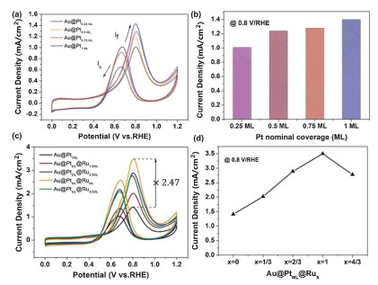
The Au@Pts-ML catalyst was characterized by TEM, HAADF-STEM and energy-dispersive X-ray spectroscopy (EDX) elemental mapping, which reveals that momolayer Pt shell was uniformly coated on the surface of the Au NWs (Fig. 2c). On the basis of the Au@Pt core-shell nanostructures, different layers of Ru were further deposited on these core-shell NWs via the UPD of Cu and galvanic replacement with RuCl3. As shown in Fig. S2 (Supporting information), the cyclic voltammogram (CV) of the Au@PtML NWs is obtained in N2-saturated 0.5 mol/L H2SO4 containing 5 mmol/L CuSO4 electrolyte. NWs of Au@PtML@Rux-ML with different Ru coverage (x=1/3, 2/3, 1 and 4/3) can be obtained by negative linear scanning voltammetry from 0.9 V to different termination potential in the above solution followed by adding 25 mL of RuCl3 (5 mmol/L) into the solution. The distribution of Ru, Pt and Au in the NWs are provided by the STEM image and EDX elemental mapping (Fig. 2d and Fig. S3 in Supporting information) of Au@PtML@Ru1/3ML NWs and Au@PtML@RuML NWs (Fig. S4 in Supporting information). By comparing the EDX data, the amount of Pt is almost the same and the amount of Ru of Au@PtMLRuML is three times as much as Au@PtMLRu1/3ML, which is in good agreement with the electrochemistry data. While Pt-Ru alloyed catalysts usually exhibit high activity and enhanced durability toward MOR, systematic study of the structure-dependent electrocatalytic properties of Au@Pts-ML and Au@PtML@Rux-ML core-shell NWs is conducted to optimize the catalytic performance. Figs. 3a and c show MOR activity associated with different Au@Pts-ML and Au@PtML@Rux-ML catalysts measured in 0.1 mol/L HClO4 aqueous solution with 0.5 mol/L CH3OH at a sweep rate of 50mV/s, and the MOR oxidative current density at 0.8 V vs. RHE are compared in Figs. 3b and d. As the nominal Pt coverage increases from 0.25 ML to 1 ML (as indicated in Fig. 3b), the MOR activity increases accordingly.

|
Download:
|
| Fig. 3. MOR performance of Au@Pts-MLand Au@PtML@RuX. (a, c) The CV of Au@Pts-ML and Au@PtML@Rux-ML in 0.1 mol/L HClO4 + 0.5 mol/L CH3OH (at 50 mV/s scan rate). (b, d) Comparison of oxidative MOR current density at 0.8 V vs. RHE. | |
This is fully consistent with the trend in the ECSAPt shown in Fig. S5 (Supporting information), indicating that the MOR performance directly correlates with ECSAPt. Similar trend can be derived by comparing the magnitude of the Pt-oxide reduction peaks. For these metal overlayers, the activity improvement originates from a combination of Au-Pt ligand effects and local strain effects manipulated by the underlying Au(111) lattice. The Au NWs have a Boerdijk-Coxeter helix-type structure dominated by (111) facets. As studied by Adzic et al., PtML/Au(111) with tensile strain exhibits over seven-fold enhancement in peak current density with respect to Pt(111) (the most active low-index plane of Pt) [31]. In addition, the electronic interaction between PtML and the Au substrate results in a weakened binding strength of COads, and efficiently catalyze the COads oxidation, which is the rate-limiting step in the indirect mechanism of the MOR.
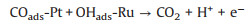
It is widely acknowledged that the MOR could go through a dual-path mechanism: direct pathway (reactive intermediates) and indirect pathway (poisoning intermediates). This is consistent with previous reports that the electrochemical oxidation of methanol on Pt-based surfaces proceeds preferentially through the indirect pathway, where methanol molecules sequentially undergoes dissociative adsorption, dehydrogenation to form COads and oxidation of the COads, the last step of which is considered to be the rate-limiting step. And the poisoning intermediates are determined mainly as adsorbed COads, which would be hardly stripped out until the OHads is generated on the Pt surfaces under high electrode potential. Fortunately, the additional Ru atoms can promote water oxidation to increase the availability of OHads at lower overpotential and consequently enhance the activity via the bifunctional Langmuir-Hinshelwood mechanism:
|
(2) |
As shown in Fig. 3c, Au@PtML@RuML exhibits a negative shift in onset potential and 2.47 times enhancement in peak current density at 0.8 V/RHE with respect to Au@PtML, establishing it as the best-performing catalyst among all the samples. Previous studies by Mavrikakis et al. demonstrated the free energy change of CO adsorption as one of the key descriptors, which determines the onset potential for MOR. So the negative shift of the onset potential toward MOR on Au@PtML@RuML NWs agrees well with the finding and the higher If/Ib (forward and backward current density respectively) ratio implies that the methanol could be effectively oxidized during the forward potential scan, producing less poisoning species, thereby possessing higher tolerance of CO poisoning. We also found that the activity based on the weight of Pt and all metals (including Au, Pt, Ru) shows similar trend for different alloy catalysts and the performance of the best one Au@PtML@RuML is superior to that of many similar alloy catalysts in recent studies (Fig. S6 and Table S1 in Supporting information). To further investigate the structure-performance relationship in Au-Pt-Ru trinary system, the current density of nanowires of bare Au, Au@RuML and Au@RuML@PtML is evaluated under the same experimental condition, as shown in Fig S7 (Supporting information). The nanowires of bare Au and Au@RuML have negligible activity in catalyzing MOR while Au@RuML@PtML exhibits much higher activity. When a monolayer of Ru atoms is deposited on Au NWs firstly, they tend to form islands on Au surface, and the following Pt deposit on the uncovered Au surface, resulting in a similar structure of Ru-Pt interface on Au. However, it is still lower than the performance of Au@PtML@RuML. The inferior performance may come from the direct landing of Ru on Au and less available Au surface for Pt deposition. Hence the atom-precision fine-tune of Au@PtML@RuML provides the most favorable catalyst for MOR.
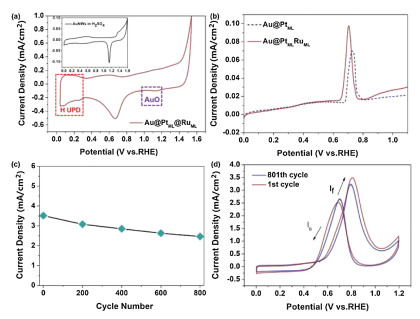
Similar to the trend in Au@Pts-ML, the current density for MOR were found to depend on the surface coverage of Ru atoms, exhibiting an increasing catalytic activity with increasing Ru coverage, until reaching a maximum at nominal surface Ru coverage of 1 ML. From the CV of Au@PtML@RuML in N2-saturated 0.1 mol/L HClO4 solution, the peak of Au oxidation at 1.17 V vs. RHE nearly disappears as compared to the inset figure of Au NWs in 0.5 mol/L H2SO4, suggesting the surface of the electrocatalyst was covered by Pt-Ru atoms (Fig. 4a). However, the activity began to subsequently decrease when more than 1 ML of Ru is deposited on the surface (Fig. 3d). The volcano trend in the MOR activity suggests a remarkable impact of the Ru amount on the catalytic activity of core-shell nanostructures. With the increase of Ru deposition, the ligand effect on the underlying Pt layer will be enhanced, which contributes to lower the d-band center of Pt and weaken the CO adsorption on Pt. However, less Pt sites will be exposed in this case. The best performance come with a balance between enhanced intrinsic activity and enough active sites and hence with intermediate coverage of Ru on the surface of the Au@PtML nanowires. Actually, the peak position of the volcano plot indicates an incomplete coverage of the substrate with nominal one monolayer of Ru.

|
Download:
|
| Fig. 4. The electrochemical characterization and stability test. (a) CVs of Au@PtML@RuML in N2-saturated 0.1 mol/L HClO4 solution at 50 mV/s, the inset figure depicts CV of Au NWs in 0.5 mol/L H2SO4. (b) The CO stripping current measured via potential sweep at 5mV/s in 0.1 mol/L HClO4 (adsorptions at 50 mV). Only the positive-going sweeps are shown for clarity. (c) The relationship between the peak current density and the cycle number. (d) CVs of Au@PtML@RuML before and after 800 potential cycles. The 801th cycle in freshly prepared 0.5 mol/L CH3OH + 0.1 mol/L HClO4 solution, scan rate: 50 mV/s. | |
The effect induced by alloying of Ru and Pt is further evaluated by CO stripping voltammetry. As shown in Fig. 4b, the CO stripping potential for Au@PtML@RuML is slightly lower than that of Au@PtML, in agreement with previously established results (Fig. 3c), consolidating that the d-band center of the Pt layer is reduced by the ligand effect imposed by Ru. As shown in Fig. 3c, the ratio of If to Ib for Au@Pt@RuML is apparently larger than that for Au@PtML, indicating less poisoning effect for Au@PtML@RuML than for Au@PtML, in agreement with the conclusion derived from the CO stripping (Fig. 4b). However, the down-shift of the d-band center also reduces the adsorption energy and surface coverage of CO species on the catalyst and lowers the catalytic activity. Only when the two effects strike a balance, the sample of Au@PtML@RuML achieves the optimum MOR performances and a volcano-shape dependence of the catalytic activity on the coverage is observed.
The stability or durability of the catalyst is the most critical requirement of catalysts for practical application of fuel cells. The above-mentioned catalysts were further evaluated through an accelerated durability test (Fig. 4c). The peak current density of methanol oxidation obtained from forward CV sweep decreases gradually with the increase of the cycle number. After 800 cycles, the Au@PtML@RuML NWs retains 62.4% of the initial catalytic activity. This phenomenon may result from of methanol consumption during the successive scans and accumulation poisonous species on the surface of the electrocatalyst. Actually the consumption of methanol in the whole process is very low. So it is suggested that the main reason for the decrease of current density in the 800 cycles may be the accumulation poisonous species on the surface of the electrocatalyst. Hence, the catalyst was evaluated again after 800 cycles in freshly prepared electrolyte (0.5 mol/L CH3OH+0.1 mol/L HClO4) and the peak current density was 3.24 mA/cm2, equivalent to 92.4% of the initial value (Figs. 4c and d, Fig. S8 in Supporting information). The fresh electrolyte solution provides the diffusion conditions for the poisonous species gathered on the electrocatalyst surface, and leads to the recovery of the MOR performance. The excellent long-term cycle stability of the multilayer nanostructure further reveals that Au@PtML@RuML catalyst may be a good alternative catalyst in DMFC.
In summary, we successfully synthesized nanowires of Au@Pts-ML and Au@PtML@Rux-ML with ultralow loading of noble metals and high MOR performance via UPD and galvanic replacement. The enhanced MOR activities of these multilayer structures can be attributed to the Au-NW substrate as an electron pathway for Pt monolayer and ligand effect from Ru, which decreases the adsorption energy by lowering the d-band center of Pt. The Ru sites also promote CO oxidation on Pt via the enhanced adsorption of OH groups, as supported by the CO stripping test. We present a correlation between the electrocatalytic activity of the NWs and the surface coverage of noble metals. The optimum Ru coverage in Au@PtML@RuML comes at the balance between exposing Pt active sites and imposing ligand effect and bifunctional mechanism by Ru coating. This avenue may shed light on the rational design of cost-efficient electrocatalysts for the portable DMFC in the future.
Declaration of competing interestThe authors declare that they have no known competing financial interests or personal relationships that could have appeared to influence the work reported in this paper.
AcknowledgmentsThis work was financially supported by the Natural Science Foundation of Tianjin, China (No. 18JCYBJC20600), the National Natural Science Foundation of China (Nos. 62074123, 61701543) and Institute of Energy, Hefei Comprehensive National Science Center (No. 19KZS207).
Appendix A. Supplementary dataupplementary material related to this article canbefound, in the online version, at doi: https://doi.org/10.1016/j.cclet.2020.11.071.
| [1] |
L. Yang, J.H. Chen, X.X. Zhong, et al., Colloids Surf. A:Physicochem. Eng. Asp. 295 (2007) 21-26. DOI:10.1016/j.colsurfa.2006.08.023 |
| [2] |
H. Tang, J.H. Chen, M.Y. Wang, et al., Appl. Catal. A Gen. 275 (2004) 43-48. DOI:10.1016/j.apcata.2004.07.018 |
| [3] |
Y.Q. Kang, Q. Xue, Y. Zhao, et al., Small (2018) e1801239. |
| [4] |
S.L. Yin, Z.Q. Wang, X.Q. Qian, et al., ACS Sustainable Chem. Eng. 7 (2019) 7960-7968. DOI:10.1021/acssuschemeng.9b00872 |
| [5] |
J.Q. Chang, L.T. Song, Y.Q. Xu, et al., Nano Res. 13 (2019) 67-71. |
| [6] |
K. He, T.T. Tsega, X. Liu, et al., Angew. Chem. 131 (2019) 12029-12035. DOI:10.1002/ange.201905281 |
| [7] |
L.Y. Peng, L. Gan, Y.P. Wei, et al., J. Phys. Chem. C 120 (2016) 28664-28671. DOI:10.1021/acs.jpcc.6b10445 |
| [8] |
W.J. Lei, M.G. Li, L. He, et al., Nano Res. 13 (2020) 638-645. DOI:10.1007/s12274-020-2666-3 |
| [9] |
C. Luo, J.H. Yang, J.L. Li, et al., J. Electroanal. Chem. 873 (2020) 114423. DOI:10.1016/j.jelechem.2020.114423 |
| [10] |
A.M. Fathi, H.T. Handal, A.A. El-Kady, Carbon Lett. 31 (2021) 253-267. DOI:10.1007/s42823-020-00160-y |
| [11] |
C.W. Zhang, L.B. Xu, J.F. Chen, Chin. Chem. Lett. 27 (2016) 832-836. DOI:10.1016/j.cclet.2016.02.025 |
| [12] |
D. Ma, B. Hu, W.D. Wu, et al., Nat. Commun. 10 (2019) 3367. DOI:10.1038/s41467-019-11176-y |
| [13] |
X.Y. Zhao, H.C. Zhao, J.F. Sun, G. Li, R. Liu, Chin. Chem. Lett. 31 (2020) 1782-1786. DOI:10.1016/j.cclet.2020.01.005 |
| [14] |
F. Chang, S. Shan, V. Petkov, et al., J. Am. Chem. Soc. 138 (2016) 12166-12175. DOI:10.1021/jacs.6b05187 |
| [15] |
W. Hong, J. Wang, E. Wang, Small 10 (2014) 3262-3265. DOI:10.1002/smll.201400059 |
| [16] |
T. Zhang, Y. Sun, X. Li, et al., Small Methods 4 (2019) 1900709. |
| [17] |
S. Chen, S. Thota, X. Wang, J. Zhao, J. Mater. Chem. A 4 (2016) 9038-9043. DOI:10.1039/C6TA02914K |
| [18] |
L. Huang, X. Zhang, Q. Wang, et al., J. Am. Chem. Soc. 140 (2018) 1142-1147. DOI:10.1021/jacs.7b12353 |
| [19] |
F. Amouzad, K. Zarei, J. Electron. Mater. 49 (2020) 3583-3590. DOI:10.1007/s11664-020-08054-5 |
| [20] |
N. Dimitrova, M. Dhifallah, T. Mineva, et al., RSC Adv. 9 (2019) 2073-2080. DOI:10.1039/C8RA08782B |
| [21] |
W. Guo, X. Yao, L. Peng, et al., Chin. Chem. Lett. 31 (2020) 836-840. DOI:10.1016/j.cclet.2019.06.018 |
| [22] |
N. Aoki, H. Inoue, T. Okawa, et al., Electrocatalysis 9 (2017) 125-138. |
| [23] |
M. Li, Q. Ma, W. Zi, et al., Sci. Adv. 1 (2015) e1400268. DOI:10.1126/sciadv.1400268 |
| [24] |
R. Liu, J.F. Liu, Z.M. Zhang, et al., J. Phys. Chem. Lett. 5 (2014) 969-975. DOI:10.1021/jz500238z |
| [25] |
Z.Q. Niu, S.P. Chen, Y. Yu, et al., Nano Res. 13 (2020) 2564-2569. DOI:10.1007/s12274-020-2900-z |
| [26] |
Y. Zhang, J. Zhang, Z. Chen, et al., Sci. China Mater. 61 (2018) 697-706. DOI:10.1007/s40843-017-9157-9 |
| [27] |
T.V. Cleve, S. Moniri, G. Belok, K.L. More, S. Linic, ACS Catal. 7 (2016) 17-24. |
| [28] |
E. Herrero, L.J. Buller, H.D. Abruña, Chem. Rev. 101 (2001) 1897-1930. DOI:10.1021/cr9600363 |
| [29] |
D. Gokcen, Q. Yuan, S.R. Brankovic, J. Electrochem. Soc. 161 (2014) D3051-D3056. DOI:10.1149/2.007407jes |
| [30] |
A. Kuzume, E. Herrero, J.M. Feliu, R.J. Nichols, D.J. Schiffrin, J. Electroanal. Chem. 570 (2004) 157-161. DOI:10.1016/j.jelechem.2004.02.012 |
| [31] |
M. Li, P. Liu, R.R. Adzic, J. Phys. Chem. Lett. 3 (2012) 3480-3485. DOI:10.1021/jz3016155 |
| [32] |
A.I. Danilov, E.B. Molodkina, Y.M. Polukarov, V. Climent, J.M. Feliu, Electrochim. Acta 46 (2001) 3137-3145. DOI:10.1016/S0013-4686(01)00605-3 |
| [33] |
D. Chen, Q. Tao, L.W. Liao, et al., Electrocatalysis 2 (2011) 207-219. DOI:10.1007/s12678-011-0054-1 |
| [34] |
S. Moniri, T. Van Cleve, S. Linic, J. Catal. 345 (2017) 1-10. DOI:10.1016/j.jcat.2016.11.018 |
| [35] |
K. Sasaki, J.X. Wang, H. Naohara, et al., Electrochim. Acta 55 (2010) 2645-2652. DOI:10.1016/j.electacta.2009.11.106 |
| [36] |
J. Suntivich, Z. Xu, C.E. Carlton, et al., J. Am. Chem. Soc. 135 (2013) 7985-7991. DOI:10.1021/ja402072r |
| [37] |
R. Loukrakpam, Q. Yuan, V. Petkov, et al., Phys. Chem. Chem. Phys. 16 (2014) 18866-18876. DOI:10.1039/C4CP02791D |
| [38] |
Y. Ando, K. Sasaki, R. Adzic, Electrochem. Commun. 11 (2009) 1135-1138. DOI:10.1016/j.elecom.2009.03.031 |
| [39] |
W. Chrzanowski, A. Wieckowski, Langmuir 13 (1997) 5974-5978. DOI:10.1021/la970193c |
| [40] |
J. Zou, M. Wu, S. Ning, et al., ACS Sustainable Chem. Eng. 7 (2019) 9007-9016. DOI:10.1021/acssuschemeng.9b01270 |
| [41] |
P. Ochal, J.L. Gomez de la Fuente, M. Tsypkin, et al., J. Electroanal. Chem. 655 (2011) 140-146. DOI:10.1016/j.jelechem.2011.02.027 |
| [42] |
Z. Tao, W. Chen, J. Yang, et al., Sci. China Mater. 62 (2018) 273-282. |
| [43] |
T.T. Gebremariam, F. Chen, B. Kou, et al., Electrochim. Acta 354 (2020) 136678. DOI:10.1016/j.electacta.2020.136678 |
| [44] |
Q.L. Wang, R. Fang, L.L. He, et al., J. Alloys Compd. 684 (2016) 379-388. DOI:10.1016/j.jallcom.2016.05.188 |
| [45] |
I. Banerjee, V. Kumaran, V. Santhanam, J. Phys. Chem. C 119 (2015) 5982-5987. DOI:10.1021/jp5113284 |
| [46] |
X. Jiang, X.Y. Qiu, G.T. Fu, et al., J. Mater. Chem. A 6 (2018) 17682-17687. DOI:10.1039/C8TA06676K |
| [47] |
Q. Xue, J. Bai, C. Han, et al., ACS Catal. 8 (2018) 11287-11295. DOI:10.1021/acscatal.8b03447 |
| [48] |
Y.H. Zhu, J.T. He, C. Shang, et al., J. Am. Chem. Soc. 136 (2014) 12746-12752. DOI:10.1021/ja506554j |