 2021, Vol. 32


b Qilu University of Technology (Shandong Academy of Sciences), Jionan 250014, China
In recent years, electrochemical energy storage devices such as ion capacitors have received considerable attention for the development of large-scale energy storage systems [1]. Ion capacitors are energy storage devices that are generally composed of a battery-type electrode and an electric double-layer capacitor-type electrode. They have the advantages of the high-power density of capacitors and the high energy density of batteries [2-4]. Due to these advantages, ion capacitors have attracted wide interest, and efforts are being made to improve their performance [3, 5-14]. Electrolytes play an important role in determining the performance of ion batteries, supercapacitors, and ion capacitors [8, 15-18]. The most widely used liquid electrolytes are aqueous or organic electrolytes (such as carbonate-based electrolytes) [19-22]. While aqueous electrolytes are safe, economic and environmentally friendly, they have a narrow potential window (~1.23 V) [23], thus restricting their practical applications. Organic electrolytes, on the other hand, show good thermodynamic stability and have a wide potential window but are inflammable and moisture sensitive [24, 25]. Electrochemical energy storage based on aqueous electrolytes is potentially safer and environmentally more benign than that based on nonaqueous electrolytes, which typically employ highly flammable organic solvents as the electrolyte solvent. The low thermodynamic stability of water is disadvantageous for aqueous capacitors in terms of volumetric and gravimetric energies (E) as the metric scale, which varies with the square of the maximum operating voltage (U) (E = 1/2 CU2) [26]. By comparison, commercial nonaqueous electrochemical capacitors can currently attain a potential of 3.0 V. According to the relation E = 1/2 CU2, the energy density is proportional to the square of the voltage, which is advantageous for high-voltage capacitors that use organic electrolytes. In most electrochemical capacitors, organic electrolytes, such as those based on propylene carbonate (PC), are used instead of aqueous electrolytes [27-29]. Unfortunately, the toxicity and flammability of the organic electrolytes raise pollution and safety related concerns [26].
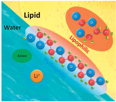
In this study, we developed water–lipid (PC) mixed electrolytes using an amphiphilic polymer, so that water and PC are mutually soluble with the conventional low-cost lithium acetate salt. Polyethylene glycol (PEG) has hydrophilic and lipophilic ends that can hydrate water, thereby allowing the mixing of water and lipid (Fig. 1 shows the schematic description of the strategy). This, in turn, allows to combine the advantages of aqueous and organic electrolytes. Electrochemical tests show that these water–lipid mixed electrolytes have a wide potential window of about 2.8 V. Low-cost and safe electrolytes that can be used in a > 2 V ion capacitor were prepared. In contrast, the potential window hardly exceeds 2 V when conventional aqueous electrolytes are used in an ion capacitor [30]. Using the mixed electrolytes, the energy density of an ion capacitor can be enhanced due to the high operating voltage.

|
Download:
|
| Fig. 1. Schematic of the water–PEG–lipid ternary electrolyte. | |
Preparation of water–PEG–lipid ternary electrolyte (TE): Water–PEG–lipid TEs, which are composed of lithium acetate (or LiTFSI), water, PEG and PC, were prepared. First, the amounts of deionized water, PEG200 and PC (mass ratio of water: PEG: PC was 4:6:4, at room temperature (30 ℃), and this electrolyte will be henceforth denoted as LiAc464 (or LiTFSI464); (the experimental scheme for determining the mixing ratio is described in the supporting information) were calculated. Next, the three components were mixed in a 20 mL glass vial, and a calculated mass of lithium acetate was added to it. Following this, the vial was sealed, heated at 80 ℃ for 12 h, and left overnight for complete dissolution of the salt. Lithium acetate, PC and PEG200 were purchased from J & K Scientific Ltd.
Preparation of activated carbon (AC) electrode: AC powder was purchased from Nanjing XFNANO Materials Tech Co., Ltd. First, the active material powder, polytetrafluoroethylene (PTFE) binder solution (60 wt% in H2O), and carbon black powder were mixed with ethanol until a homogenous slurry was formed. The slurry was transferred onto a carbon cloth (WOS1009, CeTech, Taiwan) once the ethanol evaporated at room temperature. The resulting electrodes, which had a mass density per unit area of 7 mg/cm2 and contained 80 wt% of the active material, 10 wt% of PTFE, and 10 wt% of carbon black, were used for all the electrochemical experiments.
Preparation of lithium manganate (LMO) electrode: First, LMO powder, polyvinylidene fluoride (PVDF) binder power, and carbon black powder were mixed with ethanol until a homogenous slurry was formed. The slurry was transferred onto a stainless steel mesh once the ethanol evaporated at room temperature. The resulting electrodes had a mass density per unit area of 7 mg/cm2 and contained 80 wt% of the active material, 10 wt% of PVDF, and 10 wt% of carbon black. The commercial LMO cathode, which was a single side-coated commercialized product containing 17 mg/cm2 of active material on Al foil, was purchased from MTI Corporation (Shenzhen).
Fabrication of ion capacitor: Ion capacitors were assembled in a coin cell using the lithium manganate (LMO) and AC electrodes; a nonwoven fabric membrane was used as the separator. The nonwoven fabric membrane (NKK-MPF30AC-100) was purchased from Nippon Kodoshi Corporation (Kochi, Japan). All operations were conducted in an atmospheric environment.
Electrochemical test: Cyclic voltammetry (CV) and linear sweep voltammetry (LSV) measurements were conducted using an electrochemical working station (CHI760E, Shanghai, China) with a three-electrode system containing 1 mol/kg LiAc electrolyte and 1 mol/kg LiAc464. A Hg/HgO electrode was used as the reference electrode. Galvanostatic charge/discharge (GCD) tests were conducted using the CT-2001A (Wuhan Land Electronic Co., Ltd.) battery testing system. Raman spectra were obtained on the Horiba JobinYvon HR 800 Raman spectrometer.
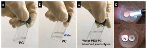
Solubility and flammability of the electrolytes were examined. Figs. 2a–c illustrate the preparation of water–PEG–lipid TEs. Water and PC were immiscible, resulting in the formation of an oil–water interface. After adding the amphiphilic polymer PEG200 and lithium acetate, a homogeneous and transparent electrolyte was obtained. PEG facilitated the dissolution of water and PC due to the presence of the hydrophilic and lipophilic segments in the PEG chain. These aqueous–organic electrolytes comprised the advantages of both water and organic solvents, including the wide electrochemical potential window of organic solvents and the economic feasibility and safety of water. The flammability of PC and water-PEG-PC TEs was tested. The TEs could not be ignited using a flame thrower (high-temperature butane flames, 1300 ℃), whereas PC was ignited and burnt (Fig. 2d). Thus, the safety aspect of the water–PEG–lipid TE was confirmed.

|
Download:
|
| Fig. 2. Photos of (a) propylene carbonate, (b) water/propylene carbonate solution and (c) water–PEG–lipid ternary electrolyte. (d) Propylene carbonate and water–PEG–lipid ternary electrolyte were burnt using butane flames. PC was ignited, while TE could not be ignited. | |
Colloidal properties and conductivity of the electrolytes were tested, and the results are presented in Table S1 (Supporting information). The relatively low zeta potential suggests that the LiAc464 electrolyte may not stable enough (stability of colloids). To prepare a stable water-PEG-PC TE, LiTFSI was used as the organic salt owing to its good solubility in both water and PC. Indeed, the zeta potential and stability were obviously improved when LiTFSI was used as the salt; however, this salt is expensive.
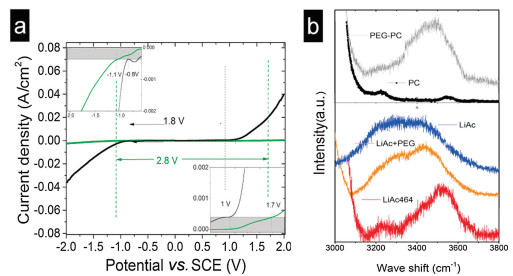
The electrochemical potential window of the water–PEG–lipid TE was tested using LSV. The results revealed that the thermodynamic stability was enhanced, and the potential window increased from 1.8 V to 2.8 V when the water–PEG–lipid TE was used. The LSV curves of the electrolytes were determined on Pt working electrodes at a scan rate of 10 mV/s versus a saturated calomel electrode (SCE) as the reference electrode (Fig. 3a). For comparison, aqueous lithium acetate electrolytes were also tested under the same conditions. The water–PEG–lipid TE showed a wider potential window of 2.8 V, while aqueous electrolytes displayed a narrow potential window of ~1.8 V. Detailed LSV curves are shown in Fig. 3. At the anode, hydrogen evolution was suppressed when PEG and PC were added, and the inflection point of the hydrogen evolution curve negatively shifted by ~0.3 V (from −0.8 V to −1.1 V). In case of the cathode, the inflection point of the oxygen evolution curve showed a gradual positive shift from 1 V to 1.7 V. The LSV results suggest that the thermodynamic stability could be enhanced by this method.

|
Download:
|
| Fig. 3. (a) Linear sweep voltammetry curves of electrolytes in aqueous electrolytes and water–PEG–lipid lithium acetate ternary electrolyte. Inset: details of the LSV of electrolytes. Pt electrode was used as the working and counter electrodes, while SCE was used as the reference electrode. (b) Raman spectra of the electrolytes and solvents. | |
Structures of the electrolytes were studied on the basis of the Raman spectrum (Fig. 3b). The spectrum of pure water can be resolved into two bands centered at 3200 and 3400 cm−1. The Raman spectrum of pure water showed strong O-H stretching band (3200 cm−1), which was mainly attributed to bulk water. Various hydrogen bonding environments in water resulted in a broad Raman band [31]. The Raman spectra of aqueous LiAc electrolytes and water exhibited broad distribution due to the presence of free water. Upon the addition of PEG and PC, free water molecules were strongly bonded to PEG. Owing to this, the Raman spectrum of the LiAc464 electrolyte exhibited two split peaks instead of a continuous broad spectrum. The split peak can be attributed to the water molecules hydrated with Li+ and PEG due to the absence of bulk water, and this increased the thermodynamic stability [32-35]. The spectra of the other components of the electrolyte were also examined. While an O−H stretching band (3400 cm-1) was observed for PEG, no obvious peaks were observed in the spectrum of PC in the same range. The Raman spectrum of LiAc-PEG showed a weakened O−H stretching band (3200 cm-1) compared to that of LiAc upon the addition of PEG.
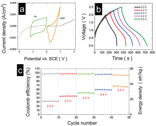
The electrochemical performance of the cathode and anode in electrolytes was examined using LSV, CV and GCD. First, the performance of the LiAc464 electrolyte in anode (AC electrode) was tested using CV. A carbon cloth was used as a current collector. The CV curves of the AC and LMO electrodes in the LiAc464 electrolyte are shown in Fig. 4a. A reversible redox pair was observed, and the LiAc464 electrolyte enabled the reversible Li+ deintercalation/intercalation in the LMO electrode. The AC electrode had a Coulomb efficiency of more than 95% at an operating potential of –1.2 V and scan rate of 5 mV/s.

|
Download:
|
| Fig. 4. (a) CV curves of the AC and LMO electrodes and the current collector in LiAc464 (scan rate of 5 mV/s). (b) GCD curves of the ion capacitor at different operating voltages (2.0–2.5 V). (c) Cycling performance and Coulombic efficiency of the capacitor using the LiAc464 at different operating voltages (2.0–2.5 V). (c) Energy density and Coulombic efficiency of the ion capacitor with variable voltages. The data above were based on the total mass of LMO and AC, and the operation was conducted at a current density of 3.3 mA/cm2. | |
The performance of electrolytes was tested using a Li ion capacitor. The ion capacitor constructed using the AC–LMO electrode system was assembled and evaluated in LiAc and the LiAc464 electrolyte. The ion capacitor was operated through charge/discharge cycles. Instead of a high rate, a low rate of 0.6 A/g (based on the AC mass of the AC electrode) was used to demonstrate the stability of the electrolyte. Figs. 4b and c show that the energy density based on the total active mass ranged from 18 Wh/kg to 37 Wh/kg. The Coulombic efficiency of the ion capacitor ranged from 99% to 95% when the operating voltage was increased from 2.0 V to 2.5 V.
The ion capacitor was also tested using aqueous LiAc to confirm the better performance of the LiAc464 electrolyte compared to LiAc. When LiAc was used, the capacity of the ion capacitor decayed evidently as the voltage was increased beyond 2.0 V (Fig. S1 in Supporting information). The decay was attributed to the continuous decomposition of the aqueous LiAc electrolyte, especially when the operating voltage was 2.2 V. Fig. S1b shows that the IR drop of the GCD curves of the aqueous capacitor was maintained at ~0.15 V when operated from 1.4 V to 2.0 V. However, when the voltage exceeded 2.0 V and after cycling, the IR drop of the GCD curves reached 0.24 V, indicating severe decomposition of the aqueous electrolytes accompanied by bubble generation and an increased voltage drop. Fig. S1c shows the typical voltage profiles of the capacitor operated at 2.2 V. Compared to the first cycle, the tenth cycle exhibited a remarkable decay in the capacity of the capacitor; however, the voltage drop was doubled. The decomposition of the aqueous electrolyte can also be confirmed from the images of the cell (Fig. S2 in Supporting information). The separator became dry after 200 cycles from 1.4 V to 2.2 V. By contrast, the capacitor was stable even at 2.4 V when the LiAc464 electrolyte was used; the separator was transparent and moist even after cycling. The energy density of the cell improved when the LiAc464 electrolyte was used compared to when the aqueous LiAc electrolyte was used, due to the high cell voltage of the former. The above results justify the obvious decomposition of the aqueous LiAc electrolyte when the voltage exceeds 2.0 V. Hence, the energy densities of the two capacitors operated at 2.0 and 2.4 V were compared. The Ragone plot (Fig. S3a in Supporting information) of the ion capacitor in aqueous and water–PEG–lipid mixed lithium acetate electrolytes showed that the energy density of the capacitor was higher (32 Wh/kg) when the LiAc464 electrolyte was used compared to when LiAc was used (24 Wh/kg) at a current density of 3.3 mA/cm2. However, the aqueous electrolyte exhibited a good performance at high power. The stability of the LiAc464 electrolytes was also tested. When the LiAc464 electrolyte was used, the ion capacitor maintained 60% of the capacity after 2000 cycles at 2.4 V (Fig. S3b in Supporting information). The capacity degraded after cycling due to the decomposition of the electrolyte (the coulombic efficiency was about 97% when the ion capacitor was operated at 2.4 V, suggesting slight decomposition of the electrolytes). Electrochemical tests confirmed the better performance of the mixed electrolyte compared to the aqueous electrolyte in terms of energy density.
To demonstrate the practical application, a commercial LMO cathode (with large mass load, 17 mg/cm2 activated material on Al foil) was used to fabricate the Li ion capacitor. The performance of the electrolytes was tested. The energy density was lower than that obtained using a steel current collector (small mass load, ~7 mg/cm2). The operating voltages of the ion capacitor using the aqueous electrolyte and mixed electrolyte were 1.6 and 2.2 V, respectively, as shown in Figs. S4-S6. Compared to the capacitor using the steel current collector, a lower operating voltage was required when Al foil was used because aluminum is more susceptible to corrosion.
In summary, a water–PEG–lipid TE was prepared to combine the advantages of water and organic solvents. The water–PEG–lipid TE had a wider potential compared to those of aqueous electrolytes, thus addressing the concerns arising from the inflammability and moisture sensitivity of the organic electrolytes. A 2.4 V-Li ion capacitor could be fabricated using the water–PEG–lipid TE to enhance the energy density relative to those obtained using aqueous electrolytes. This strategy can be used to prepare cost-effective and safe electrolytes with high thermodynamic stabilities for the development of aqueous/organic electrolytes.
Declaration of competing interestThe authors report no declarations of interest.
AcknowledgmentsThis work was supported by the National Natural Science Foundation of China (No. 11975043) and the Natural Science Foundation of Shandong Province (No. ZR2017LEM011).
Appendix A. Supplementary dataSupplementarymaterial related to this article canbefound, in the online version, at doi:https://doi.org/10.1016/j.cclet.2020.12.025.
| [1] |
M. Dai, D. Zhao, X. Wu, Chin. Chem. Lett. 30 (2020) 2053-2064. |
| [2] |
A.D. Pasquier, I. Plitz, J. Gural, F. Badway, G.G. Amatucci, J. Power Sources 136 (2004) 160-170. DOI:10.1016/j.jpowsour.2004.05.023 |
| [3] |
C. Li, X. Zhang, K. Wang, X.Z. Sun, Y.W. Ma, Carbon 140 (2018) 237-248. DOI:10.1016/j.carbon.2018.08.044 |
| [4] |
J. Zhang, Z.Q. Shi, Z.W. Xu, Chin. Chem. Lett. 29 (2018) 620-623. DOI:10.1016/j.cclet.2018.01.031 |
| [5] |
J. Ajuria, M. Arnaiz, C. Botas, et al., J. Power Sources 363 (2017) 422-427. DOI:10.1016/j.jpowsour.2017.07.096 |
| [6] |
X. Yan, X. Zhao, C. Liu, et al., J. Power Sources 423 (2019) 331-338. DOI:10.1016/j.jpowsour.2019.03.095 |
| [7] |
L. Chen, W. Zhai, L. Chen, et al., J. Power Sources 392 (2018) 116-122. DOI:10.1016/j.jpowsour.2018.04.103 |
| [8] |
Y. Zhang, P. Nie, C. Xu, et al., Electrochim. Acta 268 (2018) 512-519. DOI:10.1016/j.electacta.2018.02.125 |
| [9] |
P. Wang, G. Zhang, M.Y. Li, et al., Chem. Engin. J. 375 (2019) 122020. DOI:10.1016/j.cej.2019.122020 |
| [10] |
H.S. Ao, Y.Y. Zhao, J. Zhou, et al., J. Mater. Chem. A 7 (2019) 18708-18734. DOI:10.1039/C9TA06433H |
| [11] |
J. Yang, D. Xu, R. Hou, et al., Chin. Chem. Lett. 31 (2020) 2239-2244. DOI:10.1016/j.cclet.2019.11.044 |
| [12] |
M.Q. Liu, L.M. Chang, J. Wang, et al., J. Power Sources 469 (2020) 228415. DOI:10.1016/j.jpowsour.2020.228415 |
| [13] |
C. Li, X. Zhang, K. Wang, X.Z. Sun, Y.W. Ma, J. Power Sources 400 (2018) 468-477. DOI:10.1016/j.jpowsour.2018.08.013 |
| [14] |
S. Zhang, C. Li, X. Zhang, X. Sun, Y. Ma, ACS Appl. Mater. Interfaces 9 (2017) 17136-17144. DOI:10.1021/acsami.7b03452 |
| [15] |
J. Huang, Z. Guo, Y. Ma, et al., Small Methods 3 (2019) 1800272. DOI:10.1002/smtd.201800272 |
| [16] |
Q. Wang, L. Jiang, Y. Yu, J. Sun, Nano Energy 55 (2019) 93-114. DOI:10.1016/j.nanoen.2018.10.035 |
| [17] |
L. Xia, L. Yu, D. Hu, G.Z. Chen, Mater. Chem. Front. 1 (2017) 584-618. DOI:10.1039/C6QM00169F |
| [18] |
B. Li, J. Zheng, H. Zhang, et al., Adv. Mater. 30 (2018) 1705670. DOI:10.1002/adma.201705670 |
| [19] |
B. Babu, M. Shaijumon, J. Power Sources 353 (2017) 85-94. DOI:10.1016/j.jpowsour.2017.03.143 |
| [20] |
H.H. Shen, C.C. Hu, Electrochem. Commun. 70 (2016) 23-27. DOI:10.1016/j.elecom.2016.06.015 |
| [21] |
M. Arnaiz, E. Goikolea, T. Rojo, et al., J. Power Sources 434 (2019) 226757. DOI:10.1016/j.jpowsour.2019.226757 |
| [22] |
X. Zheng, Y. Liao, Z. Zhang, et al., J. Energy Chem. 42 (2020) 62-70. DOI:10.1016/j.jechem.2019.05.023 |
| [23] |
M. Yuan, K. Liu, J. Energy Chem. 43 (2020) 58-70. DOI:10.1016/j.jechem.2019.08.008 |
| [24] |
H. Wang, M. Yoshio, J. Power Sources 195 (2010) 389-392. DOI:10.1016/j.jpowsour.2009.06.097 |
| [25] |
A. Lewandowski, A. Olejniczak, M. Galinski, I. Stepniak, J. Power Sources 195 (2010) 5814-5819. DOI:10.1016/j.jpowsour.2010.03.082 |
| [26] |
M. Yu, Y. Lu, H. Zheng, X. Lu, Chem. Eur. J. 24 (2018) 3639-3649. DOI:10.1002/chem.201704420 |
| [27] |
A. Krause, A. Balducci, Electrochem. Commun. 13 (2011) 814-817. DOI:10.1016/j.elecom.2011.05.010 |
| [28] |
R. Kötz, M. Hahn, R. Gallay, J. Power Sources 154 (2006) 550-555. DOI:10.1016/j.jpowsour.2005.10.048 |
| [29] |
H.H. Shen, C.C. Hu, J. Electroanal. Chem. 779 (2016) 161-168. DOI:10.1016/j.jelechem.2016.04.004 |
| [30] |
Y.L. Shao, E.K. Maher, F. Sun, et al., Chem. Rev. 118 (2018) 9233-9280. DOI:10.1021/acs.chemrev.8b00252 |
| [31] |
B. Auer, J. Skinner, J. Chem. Phys. 128 (2008) 224511. DOI:10.1063/1.2925258 |
| [32] |
Y. Yamada, K. Usui, K. Sodeyama, Nat. Energy 1 (2016) 16129. DOI:10.1038/nenergy.2016.129 |
| [33] |
V. Crupi, M. Jannelli, G. Maisano, et al., J. Mol. Struct. 381 (1996) 207-212. DOI:10.1016/0022-2860(96)09308-8 |
| [34] |
S. Ko, Y. Yamada, K. Miyazaki, et al., Electrochem. Commun. 104 (2019) 106488. DOI:10.1016/j.elecom.2019.106488 |
| [35] |
M. Kozielski, M. Mühle, Z. Błaszczak, J. Mol. Liquid. 111 (2004) 1-5. DOI:10.1016/j.molliq.2003.10.002 |