 2021, Vol. 32


The development of high-performance energy storage systems for portable electronic devices, zero emission vehicles, and emerging smart grids based on renewable energy is one of the most pressing challenges facing the modern society. To date, lithium−ion batteries (LIBs) have become the most successful technology capable of meeting energy storage requirements because of their long life, pollution-free, and high energy density [1-5]. However, commercial graphite used for anode materials stores lithium ions through an intercalation mechanism, and the theoretical specific capacity of only 375 mAh/g is far from satisfying the growing demand for high-performance LIBs in modern life demand [6]. In this case, it is a long-term goal to explore electrode materials having higher specific capacities and longer lifetimes. Transition−metal oxides (TMOs) have been extensively studied as negative electrode materials for rechargeable LIBs due to their higher theoretical specific capacity and higher safety than conventional graphite [7-10]. However, most of TMOs are accompanied by low electronic conductivity, severe aggregation, and significant volume changes during charging and discharging, which lead to rapid capacity degradation and greatly hamper their practical application. Therefore, it is urgent and desirable to design and prepare replaceable materials with high stability and good conductivity.
Molybdenum dioxide (MoO2), due to its high conductivity, high reversible capacity (838 mAh/g), good chemical stability, and high electrochemical activity for lithium ions, is considered to be the most promising TMO anode materials for LIBs [11-13]. However, MoO2 still faces challenges in practical applications such as severe aggregation of active materials and slow diffusion kinetics during the repeated lithium insertion/extraction [14, 15]. Many researches have been done to overcome these shortcomings, such as reducing the size of MoO2 to the nanometer level, which shortened the transport distance of electrons and lithium ions and further reduced the resistance of the electrons and ions [12, 13, 16]. In addition, nanostructures provide higher surface activity and induce higher effective contact areas [17]. However, the construction of nanostructured MoO2 can only improve the electrochemical performance to a certain extent, and the inherent problem of effective lithium storage during charge and discharge process cannot be solved [18]. To alleviate the above problems, the researchers have synthesized MoO2-based hybrid structures through various approaches, such as carbon-coated MoO2 [19, 20], nitride-coated MoO2 [21], Mo2N nano-layer coated MoO2 [16] and graphene-MoO2 composites [22-26]. Although these advances have been made, the reversible capacity and the cycle life of these materials still require to be optimized. As a result, it is still an important topic to search a more compendious and efficient approach to synthesize MoO2-based hybrids with novel structural and multicompositional features and superior properties.
Herein, we present a self-template strategy for the fabrication of uniform MoO2 nanoparticles (NPs) immobilized on the reduced graphene oxide two-dimensional (2D) hybrid nanosheets (denoted as MoO2 NP@rGO) as a new LIB anode material via a facile polyol-assisted reflux approach coupled with calcination treatment in an inert atmosphere. Our synthetic strategy greatly simplifies the usual fabrication of MoO2-based hybrids, because it does not need multi-step reactions and it does not need to use other strong reducing agents (e.g., Ar/H2). The unique 2D multicompositional architectures endow the MoO2 NP@rGO hybrid with superior electrochemical performance when evaluated as an anode material for LIBs. Specifically, the MoO2 NP@rGO hybrid delivered a reversible capacity of 1516 mAh/g at a current density of 200 mA/g after 150 cycles. Even at 1000 mA/g, the reversible capacity remained at 641 mAh/g after 350 cycles. These results demonstrate the merits of the unique 2D porous hybrid nanoatrchitecture, which will be discussed deeply.
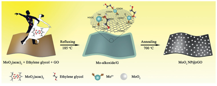
The novel 2D MoO2 NP@rGO hybrid is formed via a self-template and subsequent calcination process (see Experimental for details of the synthesis). The specific preparation process of MoO2 NP@rGO hybrid is shown in Fig. 1. GO has rich oxygen-containing functional groups (hydroxyl and carboxyl groups, etc.), which is beneficial to its strong bonding with metal ions [27]. In the subsequent reflux step, the Mo precursor, molybdenum alkoxide, was synthesized using molybdenum acetylacetonate (MoO2(acac)2) as the molybdenum source and ethylene glycol as the solvent. Due to the electrostatic interaction, the Mo precursor nucleated in situ and uniformly grown on the surface of GO to form a layer of Mo precursor, thereby forming Mo precursor/graphene (labeled Mo-alkoxide/G) [28, 29]. The metal ions on the surface of Mo-precusor reacted with the oxygen-containing functional groups on the surface of graphene. Eventually, after high-temperature calcination for 5 h, GO was completely reduced to rGO under argon atmosphere. The Mo-precusor completely decomposed and the MoO2 NPs was obtained. Finally, the strongly coupled MoO2 NP@rGO hybrid was successfully obtained. On the one hand, the 2D rGO can provide an elastic buffer space to suppress the volume expansion of the MoO2 NPs during charge and discharge and prevent the aggregation of the MoO2 NPs. On the other hand, the rGO nanosheets with good conductivity can be used as electron transport channels for MoO2 NPs, accelerating efficient charge transport. Importantly, this unique 2D hybrids possess more electrochemically active sites to provide higher capacity.

|
Download:
|
| Fig. 1. Schematic of the synthesis process of MoO2 NP@rGO hybrids. | |
The morphology and microstructure of the materials were investigated by Field-emission scanning electron microscopy (FESEM) and transmission electron microscopy (TEM). Figs. S1a and b (Supporting information) is the FESEM and TEM images of GO, which clearly shows its smooth surface. The 2D Mo-alkoxide/G was obtained after refluxing at 185 ℃ for 10 h. As shown in Figs. S1c and d (Supporting information), it can be found that the surface of the Mo-alkoxide/G is rough, which is attributed to the fact that the Mo precursor covers the surface of GO. Figs. 2a–c are FESEM images of the MoO2 NP@rGO obtained after calcination. It is apparent that the MoO2 NPs are uniformly distributed on the rGO, indicating efficient self-assembly between MoO2 NPs and rGO nanosheets during the reflux (Fig. 2c), which inhibit the aggregation of MoO2 NPs and the overlap of rGO nanosheets. TEM images further confirm that MoO2 NPs are indeed fastened on graphene sheets and there is void space between these uniform NPs with about 5 nm in diameter, consistent with the FESEM observations (Figs. 2d and e). High-resolution TEM (HRTEM; Fig. 2f) indicates well crystallization of the MoO2 NPs. The marked interplanar d-spacings of 0.243 nm correspond to the (111) lattice planes of monoclinic MoO2. Scanning TEM (STEM) and the corresponding energy-dispersive X-ray (EDX) spectrum elemental mappings of MoO2 NP@rGO in Fig. 2g clearly indicate the even distribution of elements in the graphene nanosheets, including Mo, O and C elements. The structure and composition characterization of MoO2 NP@rGO were further examined by X-ray diffraction (XRD), Raman, Brunauer-Emmett-Teller (BET) surface area, thermogravimetric analysis (TGA) and X-ray photo-electron spectroscopy (XPS) spectra (Figs. S2–S5 in Supporting information).

|
Download:
|
| Fig. 2. Morphology and structure of the MoO2 NP@rGO hybrids. (a–c) FESEM images. (d, e) TEM images. (f) HRTEM image. (g) STEM-EDX element mappings of Mo (red), O (purple) and C (green). Scale bars: (a–c, e) 100 nm, (d) 500 nm, (f) 2 nm, (g) 10 nm. | |
For comparison, we used the same method to synthesize the bare MoO2 NPs without adding GO. As shown in Fig. S6 (Supporting information), it can be found that the bare MoO2 NPs are obviously agglomerated. Using the same method, we synthesized pure rGO without adding acetylacetone molybdenum. Figs. S7a and b (Supporting information) showed its corresponding FESEM image and XRD pattern. According to FESEM, rGO is still a 2D structure with smooth surface. XRD pattern showed a characteristic peak of rGO at ~26°, indicating the formation of rGO. The diffusion of lithium ions is strongly dependent on the transport path of the active material and the accessible active sites. Compared with bare MoO2 NPs, ultra-small and uniform MoO2 NPs in MoO2 NP@rGO not only expose more active sites, facilitating lithium ion intercalation and extraction, but also shorten the diffusion path of lithium ions.
The novel structural features result in a superior excellent electrochemical performance of MoO2 NP@rGO electrodes (Fig. 3). Fig. 3a shows the initial five cyclic voltammetry (CV) curves for MoO2 NP@rGO tested at a scan rate of 0.1 mV/s. In the first discharge cycle, there is a week peak around 0.7 V, which is derived from the irreversible decomposition of the electrolyte and the formation of a solid electrolyte interface (SEI) layer. This peak disappeared in the following cycles. The discharge process of MoO2 NP@rGO can be divided into two parts between 0.01 V and 3.0 V. Above 1.0 V, there are two pairs of reversible reduction peaks at 1.20/1.29 V and 1.46/1.66 V. In the subsequent cycles, the two pairs of peaks shifted slightly to 1.27/1.37 V and 1.56/1.75 V, respectively. This is mainly due to the reversible conversion from the monoclinic phase to the orthorhombic phase and the insertion of lithium ions into the lattice of MoO2 to form LixMoO2 [30]. In the later cycles except the first cycle, when the discharge voltage is lower than 1.0 V, it can be found that there is an additional peak around 0.25 V, which is related to the three-electron reduction conversion reaction, a further reduced of LixMoO2 to Mo elemental and Li2O [31]. The two oxidation peaks at 1.42 and 1.72 V are attributed to the deintercalation and phase transition of lithium ions. The reaction equation for the insertion and removal of lithium from MoO2 is as follows [32]:

|

|

|
Download:
|
| Fig. 3. Electrochemical performance of the MoO2 NP@rGO hybrids. (a) The first five CVs at a scan rate of 0.1 mV/s. (b) Charge/discharge voltage profiles at 200 mA/g. (c) Rate capabilities at different current densities. (d) Cycling performance of MoO2 NP@rGO hybrids, bare MoO2 NPs and rGO at 200 mA/g. (e) Cycling performance at 500 mA/g and 1000 mA/g. | |
There was almost no change in the position of all redox peaks in the subsequent CV curves, indicating a high reversibility of the MoO2 NP@rGO electrodes.
Fig. 3b shows the typical galvanostatic charge-discharge curves of MoO2 NP@rGO electrode with different cycles (1st, 2nd, 20th, 50th, 100th) at 200 mA/g between 0.01 V and 3.0 V. The discharge and charge capacities of the first cycles of MoO2 NP@rGO were 1145.8 and 714.4 mAh/g, respectively, and the initial Coulomb efficiency (ICE) was 62%. The large irreversible capacity loss and low ICE of the first cycle are attributed to several irreversible processes, such as the formation of the SEI layer on the electrode surface and the decomposition of the electrolyte. In the subsequent cycle, the reversible capacities of MoO2 NP@rGO gradually increased, and the CE was maintained above 90%. Fig. 3c shows the rate capability of MoO2 NP@rGO hybrids at various current densities. The MoO2 NP@rGO nanocomposite exhibits the reversible discharge capacities of 760, 753, 725, 721, 673 mAh/g at current densities of 200, 500, 1000, 1500 and 2000 mA/g, respectively. When the current density returns back to 200 mA/g again, the capacity was as high as 1129 mAh/g. Even after 100 cycles, the capacity is increased to 1312 mAh/g.
Moreover, the MoO2 NP@rGO hybrid nanosheet electrode also confirms superb cycling performance (Fig. 3d). It can be found that the capacities of bare MoO2 NP and MoO2 NP@rGO nanocomposites have an increasing trend, which could be due to the fact that the partially reversible SEI layer and the lithium ion storage at the interface MoO2 NPs and rGO. This phenomenon has also observed in other TMOs and rGO composites [33, 34]. In the first 25 cycles, the capacity of the bare MoO2 NPs is higher than that of MoO2 NP@rGO. However, in the subsequent cycles the capacity of the bare MoO2 NPs decays rapidly, which is mainly due to its severe agglomeration and large volume changes. After 150 cycles, the capacity of MoO2 NP@rGO is as high as 1516.4 mAh/g, which is about three times the capacities of the bare MoO2 NPs (442.5 mAh/g) and rGO (526.6 mAh/g). The excellent electrochemical performance of MoO2 NP@rGO hybrids is attributed to its unique structure. That is, the introduction of rGO not only inhibits the aggregation of MoO2 NPs, but also reduces the volume change during the cycling, ensuring the structural stability of MoO2 NP@rGO. In order to further demonstrate the structural advantages of MoO2 NP@rGO at high current densities, we tested their cycling stability at the current densities of 500 and 1000 mA/g, as shown in Fig. 3e. A high capacity of 959 mAh/g can be maintained in the 300th cycle when cycled at 500 mA/g. With further increase of current density to 1000 mA/g, the capacity can still retain as high as 641 mAh/g after 350 cycles. Additionally, the MoO2 NP@rGO hybrids also outperform many MoO2/carbon-based anodes reported elsewhere (Table S1 in Supporting information).
To further understand the superior electrochemical performance of MoO2 NP@rGO hybrids, we analyzed their kinetics by a sweep-rate-dependent CV method. Fig. 4a shows the CV curves of the MoO2@rGO composite at different sweep rates. It can be clearly seen that the peak shape of the two pairs of redox peaks does not change, but the peak position shifts slightly with the increase of the sweep rate. The current (i) and sweep rate (v) have the following relationship: i = avb [35]. The b value is obtained by the slope of the linear relationship between log i and log v. In general, it is believed that when b =0.5, it is mainly diffusion controlled process, and when b is 1.0, it is totally capacitance controlled process. As shown in Fig. 4b, it is the linear curve of log i and log v. We calculated the b values of the four peaks, which are 0.85, 0.74, 0.75 and 0.72, respectively. Therefore, the charge storage process of MoO2@rGO composites is mainly capacitance controlled process. The current in the CV curves can be quantitatively divided into two parts, diffusion response and capacitance controlled process according to the following equation: i = k1v + k2v 1/2 [36, 37]. As shown in Fig. 4c, 84.1% of the charge storage is a capacitive contribution process at a sweep speed of 1.0 mV/s. The diffusion process generally occurs at the peak position. We further calculated the ratios of the capacitive contribution at different sweep rate, as shown in Fig. 4d. As the sweep rate increases, the ratios of the capacitive contribution become larger. Based on the above analysis, we propose that the MoO2@rGO hybrids have more surface capacitive response, and therefore, it is beneficial to the rapid reaction kinetics and thus exhibits excellent rate performance.

|
Download:
|
| Fig. 4. Kinetics analysis of the MoO2 NP@rGO electrode. (a) CV curves of the fresh cells at various scan rates. (b) b -value analysis using the relationship between the peak currents and scan rates. (c) Separation of the capacitive (purple region) and diffusion currents at a scan rate of 1.0 mV/s. (d) Contribution ratio of the capacitive and diffusion-controlled charges at different scan rates. (e) GITT voltage profiles. (f) Reaction resistance in discharge and charge process, respectively. | |
To explore the electrochemical resistance of MoO2@rGO during the Li-ion storage, we further carried out galvanostatic intermittent titration technique (GITT) and EIS measurements. Fig. 4e represented transient voltage responses of MoO2@rGO during the charge and discharge processes measured by GITT, where the dotted lines showed the quasi equilibrium open-circuit-voltages (OCVs). The internal resistance is obtained by dividing the voltages difference between the OCVs and the closed circuit voltages (CCVs) by the pulse current. Fig. 4f displayed the internal resistance changes of MoO2@rGO during the lithiation and delithiation processes. It was found that the internal resistance gradually decreased during the lithiation process, which can be ascribed to that the formation of metals or intermetallics enhanced the electronic conductivity and the immersion of the electrolyte accelerated the migration ions [38]. During the charging process, the internal resistance gradually increased with the release of lithium ions, which is contrary to the discussion above. The accelerated reaction kinetics of MoO2@rGO also can be evidenced by the EIS curves. The Nyquist plots of the MoO2@rGO electrode after the 1st and 50th cycles under full charge conditions are shown in Fig. S8 (Supporting information). The charge-transfer resistance (Rct) of the MoO2@rGO electrode after the 50th cycle significantly decreased than that after the 2nd cycle, which suggests improved reaction kinetics upon cycles.
In summary, we have confirmed a facile self-templating strategy for the fabrication of 2D MoO2 NP@rGO hybrid nanosheets. The present synthetic method can readily regulate and control the composition and structure of the hybrid materials. The hybrid architectures with integrated merits of each component can promote the storage and transport of Li+ ions/electrons to obtain improved lithium storage properties. This study could provide some stimulation for the engineering and construction of advanced negative electrode materials for lithium−ion batteries.
Declaration of competing interestThe authors declare that they have no known competing financial interests or personal relationships that could have appeared to influence the work reported in this paper.
AcknowledgmentsThe authors gratefully acknowledge the financial support provided by the National Natural Science Foundation of China (No. 21971145), the Taishan Scholar Project Foundation of Shandong Province (No. ts20190908), the Natural Science Foundation of Shandong Province (No. ZR2019MB024), the China Postdoctoral Science Foundation (No. 2018M632666) and the Special Fund for Postdoctoral Innovation Program of Shandong Province (No. 201901003). We also thank Anhui Kemi Machinery Technology Co., Ltd. for providing Teflon-lined stainless steel hydrothermal autoclave.
Appendix A. Supplementary dataSupplementary material related to this article can be found, in the online version, at doi:https://doi.org/10.1016/j.cclet.2020.10.024.
| [1] |
F. Cheng, J. Liang, Z. Tao, et al., Adv. Mater. 23 (2011) 1695-1715. DOI:10.1002/adma.201003587 |
| [2] |
J.B. Goodenough, Y. Kim, Chem. Mater. 22 (2010) 587-603. DOI:10.1021/cm901452z |
| [3] |
Y. Tang, Y. Zhang, W. Li, et al., Chem. Soc. Rev. 44 (2015) 5926-5940. DOI:10.1039/C4CS00442F |
| [4] |
Y. Zhang, F. Lian, J. Lu, et al., J. Energy Chem. 46 (2020) 144-151. DOI:10.1016/j.jechem.2019.10.022 |
| [5] |
S. Dou, J. Xu, X. Cui, et al., Adv. Energy Mater. 10 (2020) 2001331. DOI:10.1002/aenm.202001331 |
| [6] |
M. Liang, L. Zhi, J. Mater. Chem. 19 (2009) 5871-5878. DOI:10.1039/b901551e |
| [7] |
P. Poizot, S. Laruelle, S. Grugeon, et al., Nature 407 (2000) 496-499. DOI:10.1038/35035045 |
| [8] |
Y. Liu, H. Wan, H. Zhang, et al., ACS Appl. Nano Mater. 3 (2020) 3892-3903. DOI:10.1021/acsanm.0c00614 |
| [9] |
H. Yuan, L. Kong, T. Li, et al., Chin. Chem. Lett. 28 (2017) 2180-2194. DOI:10.1016/j.cclet.2017.11.038 |
| [10] |
D. Gu, W. Li, F. Wang, et al., Angew. Chem. Int. Ed. 54 (2015) 7060-7064. DOI:10.1002/anie.201501475 |
| [11] |
Y. Chen, S. Niu, W. Lv, et al., Chin. Chem. Lett. 30 (2019) 521-524. DOI:10.1016/j.cclet.2018.04.019 |
| [12] |
H. Lu, C. Yang, C. Li, et al., ACS Appl. Mater. Interfaces 11 (2019) 13405-13415. DOI:10.1021/acsami.9b00824 |
| [13] |
Z. Li, C. Wang, X. Chen, et al., Chem. Eng. J. 381 (2020) 122588. DOI:10.1016/j.cej.2019.122588 |
| [14] |
W. Zhang, B. Wang, H. Luo, et al., J. Alloys Compd. 803 (2019) 664-670. DOI:10.1016/j.jallcom.2019.06.337 |
| [15] |
Y. Lei, J. Hu, H. Liu, et al., Mater. Lett. 68 (2012) 82-85. DOI:10.1016/j.matlet.2011.10.043 |
| [16] |
J. Liu, S. Tang, Y. Lu, et al., Energy Environ. Sci. 6 (2013) 2691-2697. DOI:10.1039/c3ee41006d |
| [17] |
L. Zong, X. Chen, S. Dou, et al., Chin. Chem. Lett. 32 (2021) 1121-1126. DOI:10.1016/j.cclet.2020.08.029 |
| [18] |
S. Petnikota, K.W. Teo, L. Chen, et al., ACS Appl. Mater. Interfaces 8 (2016) 10884-10896. DOI:10.1021/acsami.6b02049 |
| [19] |
H.J. Zhang, T.H. Wu, K.X. Wang, et al., J. Mater. Chem. A: Mater. Energy Sustain. 1 (2013) 12038-12043. DOI:10.1039/c3ta12566a |
| [20] |
W. Tian, H. Hu, Y.X. Wang, et al., ACS Nano 12 (2018) 1990-2000. DOI:10.1021/acsnano.7b09175 |
| [21] |
S. Yoon, K.N. Jung, C.S. Jin, et al., J. Alloys Compd. 536 (2012) 179-183. DOI:10.1016/j.jallcom.2012.04.116 |
| [22] |
S. Hu, F. Yin, E. Uchaker, et al., J. Phys. Chem. C 118 (2014) 24890-24897. DOI:10.1021/jp508933c |
| [23] |
Y. Xu, R. Yi, B. Yuan, et al., J. Phys. Chem. Lett. 3 (2012) 309-314. DOI:10.1021/jz201619r |
| [24] |
K.H. Seng, G.D. Du, L. Li, et al., J. Mater. Chem. 22 (2012) 16072-16077. DOI:10.1039/c2jm32822d |
| [25] |
A. Bhaskar, M. Deepa, T.N. Rao, et al., J. Power Sources 216 (2012) 169-178. DOI:10.1016/j.jpowsour.2012.05.050 |
| [26] |
X. Wang, Y. Xiao, J. Wang, et al., J. Power Sources 274 (2015) 142-148. DOI:10.1016/j.jpowsour.2014.10.031 |
| [27] |
D.C. Marcano, D.V. Kosynkin, J.M. Berlin, et al., ACS Nano 4 (2010) 4806-4814. DOI:10.1021/nn1006368 |
| [28] |
Y. Wang, L. Yu, X.W. Lou, Angew. Chem. Int. Ed. 55 (2016) 7423-7426. DOI:10.1002/anie.201601673 |
| [29] |
L. Shen, L. Yu, H.B. Wu, et al., Nat. Commun. 6 (2015) 6694. DOI:10.1038/ncomms7694 |
| [30] |
Y. Shi, B. Guo, S.A. Corr, et al., Nano Lett. 9 (2009) 4215-4220. DOI:10.1021/nl902423a |
| [31] |
L. Zhou, H.B. Wu, Z. Wang, et al., ACS Appl. Mater. Interfaces 3 (2011) 4853-4857. DOI:10.1021/am201351z |
| [32] |
L. Zeng, C. Zheng, C. Deng, et al., ACS Appl. Mater. Interfaces 5 (2013) 2182-2187. DOI:10.1021/am303286n |
| [33] |
Y. Zhang, P. Chen, X. Gao, et al., Adv. Funct. Mater. 26 (2016) 7754-7765. DOI:10.1002/adfm.201603716 |
| [34] |
W. Wei, S. Yang, H. Zhou, et al., Adv. Mater. 25 (2013) 2909-2914. DOI:10.1002/adma.201300445 |
| [35] |
C. Yang, J.R. Feng, F. Lv, et al., Adv. Mater. 30 (2018) 1800036. DOI:10.1002/adma.201800036 |
| [36] |
W. Wang, B. Jiang, C. Qian, et al., Adv. Mater. 30 (2018) 1801812. DOI:10.1002/adma.201801812 |
| [37] |
Y.H. Xiao, D.C. Su, X.Z. Wang, et al., Adv. Energy Mater. 8 (2018) 1800930. DOI:10.1002/aenm.201800930 |
| [38] |
W.Z. Tian, W.Z. Ma, Z.Y. Feng, et al., J. Energy Chem. 44 (2020) 97-105. DOI:10.1016/j.jechem.2019.08.021 |