 2021, Vol. 32


b Key Laboratory of Yangtze River Water Environment, Shanghai Institute of Pollution Control and Ecological Security, Tongji University, Shanghai 200092, China;
c Institute for Regenerative Medicine, The Institute for Translational Nanomedicine, Shanghai East Hospital, Tongji University School of Medicine, Shanghai 200123, China
Photocatalysis has been a tremulously focus over the past three decades due to its attractive solar energy conversion ability for environmental remediations [1-4]. TiO2, being the benchmark photocatalyst with high production volume, has a market value of approximately 16, 200 million US dollars in 2018 owing to its market penetration in paints, cosmetics, food coloring and plastic industries [5-7]. However, there is plenty of room for improvement to resolve the disadvantages of TiO2, such as low responsiveness towards visible-light, agglomeration induced inactivation, high carrier recombination rate. Recent studies have shown some success in improving long wavelength light (visible-light/infrared-light) responsiveness by metal/non-metal doping and better dispersity and stability by surface modifications [2-10]. Introduction of defects and heterojunctions showed improved photoexcited charge separation and reduction of electron-holes recombination [11-15].
Among various improvement strategies, heterojunctions formation at the interface of different materials was effective in creating spatial separation of electron-hole pairs and subsequently lowering the recombination rate [16, 17]. Studies have demonstrated that typeII heterojunction photocatalysts, such as BiVO4/WO3 and TiO2/g-C3N4 exhibit desirable electron-hole separation efficiency, fast mass transfer and wide light-absorption range against type Ⅰ or Ⅲ [18, 19]. Surface-phase junctions formed within the same material, such as surface anatase/rutile junctions in TiO2, could further minimize the redox potential loss due to band structures differences and have the advantage of lowering the cost of multi-components in photocatalyst [20, 21, 22]. Moreover, the advantage of the high surface area of nano-sized photocatalysts was often compromised by particle agglomeration during photocatalytic performance [23]. While loading photocatalysts into three-dimensional matrix could effectively prevent the agglomeration, the efficiency of such materials largely relied on the capacity, the uniformity as well as the stability of the loading of photocatalyst [24, 25, 26]. Therefore, it would be appealing to create photocatalysts with three-dimensional structures of its own [27, 28, 29]. Such structure would enable effective absorption of target pollutant molecules and provide sufficient active sites for photocatalytic degradation to occur simultaneously [30, 31]. More importantly, each of the above mentioned strategies was only targeting one limitation at a time. It would be desirable to develop strategies to achieve improvements in multiple aspects simultaneously and study the synergistic effect among them.
Against this background, we set out to design synthesize TiO2-based photocatalysts with specific focus on creating structural alterations and surface junctions, aiming to improve the photocatalytic performance toward degradation of organic pollutants under visible light irradiation. By tuning the precursor ratios and introducing a pore-making agent, HClO4, into a sol-gel synthesis process, a unique type of carbon and nitrogen doped TiO2 (C, N-TiO2) with three-dimensional lamellar and porous structure and surface-phase junctions was obtained. Compared to the commercial TiO2 (P25), the as-prepared C, N-TiO2 showed enhanced visible-light responsiveness, higher adsorption capacity and degradation efficiency towards a series of organic pollutants, including rhodamine B, tetracycline and Disperse Red 60 with excellent reusability and stability.
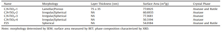
By varying the concentrations and ratios of titanium tetrachloride (as Ti source), citric acid (as C source), nitric acid (as N source), and perchloric acid (as pore-making agent), it enabled investigation on the interplay among these key components in determining the structure and properties of the as-prepared TiO2 photocatalysts (Table S1 in Supporting information). Representative micrographs of the resulted photocatalysts under scanning electron microscope (SEM) and transmission electron microscope (TEM) showed drastically different morphologies. Among them, C, N-TiO2-1 displayed a unique lamellar and porous structure (Fig. 1A) while the rest showed irregular or spherical shaped particles (Figs. S1A-H in Supporting information). In comparison, P25 showed typical spherical shape with 25 nm in diameter. Close-up SEM images of C, N-TiO2-1 (Figs. 1B and C) revealed clear lamellar structure with grain size of approximately 20−100 nm in diameters and macropores in the range of hundreds of nm distributed in each layer. The unique three-dimensional lamellar and porous structure of C, N-TiO2-1 resulted in a relatively higher specific surface area as determined by Brunauer-Emmett-Teller (BET) analysis (Table 1).

|
Download:
|
| Fig. 1. Physicochemical characterizations of the as-prepared C, N-TiO2. (A-C) Representative SEM images of C, N-TiO2-1 at increasing magnifications, with yellow and red circles indicating particles of ~20 nm and ~100 nm in size. (D) Representative TEM image of the thin layers of C, N-TiO2-1 and the corresponding selected area electron diffraction (SAED) pattern (insert). (E) High-resolution TEM image of the thin layers of C, N-TiO2-1 with surface-phase junctions highlighted in yellow dash lines. (F) AFM image of the thin layers of C, N-TiO2-1 and the corresponding height profile (insert). (G-K) Representative TEM image of C, N-TiO2-1 and the corresponding elemental mapping showing the distribution of C, N, O and Ti. | |
|
|
Table 1 Summary of the physicochemical characteristics of C, N-TiO2 in comparison with P25. |
As indicated in the SEM images, each of the lamellar layer constitutes thinner stacking sheets. These thin stacking sheets were analyzed by TEM and atomic force microscopy (AFM) following sonication. Figs. 1D and E showed that both typical TiO2 crystalline phases, i.e. anatase (lattice fringe of 0.35 nm corresponding to the 101 lattice plane) and rutile (lattice space of 0.325 nm corresponding to the 110 lattice plane) were present in these thinner sheets with abundant surface-phase junctions (highlighted in yellow dash line). Under AFM, the average thickness of these thinner sheets was approximately 1.5 nm with macropores and mesopores (Fig. 1F). Energy-dispersive spectroscopy (EDS) mapping (Figs. 1G-K) demonstrated that both carbon and nitrogen elements were uniformly distributed in the thin layers of C, N-TiO2-1. These results suggested that the choice of carbon and nitrogen sources as well as the pore-making reagent was crucial to obtain the desired structure feature of the modified photocatalysts. The amount of HNO3 not only served as a N source but also provided an acidic environment that was crucial for the formation of stable TiO2 particles with size in the range of 50−60 nm [32]. Citric acid as a C source played a role in controlling the appropriate hydrolysis rate [33]. The formation of three-dimensional lamellar and macropore structures was likely due to the introduction of HClO4 leading to gas production under high temperature [34]. The adsorption of Cl− ion to the crystal facets of anatase or rutile could contribute to the alteration of crystal growth direction that led to the formation of surface-phase junctions [35]. It is also worth mentioning that with the ideal combination of these components, the yield of the lamellar and porous structures could reach almost 100%. Without any purification processes, the as-prepared C, N-TiO2-1 showed consistent structural features in all views under SEM (Figs. S2A-D in Supporting information).
Given the unique structure, further physicochemical characterizations were focused on C, N-TiO2-1 in comparison with the others. The phase composition and crystalline structure were further confirmed by X-ray diffraction (XRD). As illustrated in Fig. S3A (Supporting information), only C, N-TiO2-1 and P25 showed characteristic diffraction peaks for both anatase and rutile, while the rest only possessed anatase phase. Similar to P25, the anatase to rutile ratio of C, N-TiO2-1 was approximately 3:1, an ideal ratio for charge separation efficiency [20, 21]. The presence of both anatase and rutile phases in C, N-TiO2-1 in microscale was further confirmed using high-resolution Raman spectroscopy (Fig. S3B in Supporting information). These results were in good agreement with the high resolution TEM (Fig. 1E) and the surface-phase junctions were expected to show an effective electron-hole separation under light irradiation [20, 21, 36].
The X-ray photoelectron spectroscopy (XPS) analysis confirmed a successful doping of C and N in the C, N-TiO2-1. As shown in Figs. 2A-D, the XPS spectra revealed the presence of C, N, O and Ti elements in C, N-TiO2-1 with an atom ratio of 19:1:29:51. As shown in Fig. 2A, the N 1s spectrum showed a main peak at 399.5 eV corresponding to the pyrrole-like nitrogen with the N atoms hosted in an interstitial position and directly bond to lattice oxygen to form Ti–O–N and/or Ti–N–O linkages [37, 38]. And in C 1s region (Fig. 2B), the fitting result showed three peaks at 284.8, 286.1 and 288.8 eV, which could be ascribed to the adventitious elemental carbon, COx compounds and carbonate species, respectively [39]. Considering the synthesis conditions (high-concentration of nitric acid and calcination at 450 ℃), the main N 1s peaks of C, N-TiO2-1 could be ascribed to interstitial N atoms in the environment of Ti–N–O and Ti–O–N linkages, due to the high electronegativity of O [39-41]. In Fig. 2C of the O 1s spectra, the one at 530.1 eV arising from O–Ti–O shifted slightly to lower energy compared with that of P25 due to N doping. The one at higher energy of 531.9 eV was attributed to the formation of hyponitrite (N2O2)2− resulting from decomposition of nitrogen precursors or oxidation of the interstitially doped N in the TiO2 lattice [41, 42]. The spectra of Ti 2p presented in Fig. 2D showed a slight shift of the Ti4+ 2p3/2 and Ti4+ 2p1/2 peaks (458.8 and 464.5 eV, respectively) to lower energy likely due to the covalent doping of N [32]. Meanwhile, the absence of Ti 2p peak at around 455 eV suggested that there were no Ti–C bonds formed, consistent with the C 1s spectra [43].

|
Download:
|
| Fig. 2. XPS analysis demonstrated successful doping of C and N in C, N-TiO2-1. XPS spectra of C, N-TiO2-1 and the fitting results in N 1s (A), C 1s (B), O 1s (C) and Ti 2p (D) regions. | |
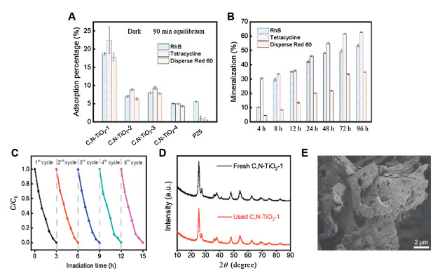
To evaluate the utility of C, N-TiO2-1 for pollutants removal, rhodamine B, tetracycline and Disperse Red 60 were used as model pollutant molecules for organic dyes and antibiotics. Under dark condition, C, N-TiO2-1 showed the highest adsorption capacity towards all three pollutant molecules (Fig. 3A). Although C, N-TiO2-1 had a similar specific surface area comparing to C, N-TiO2-3 (Table 1), the adsorption capacity of the former was approximately twice of the latter and more than three times higher than P25. These results suggested that the unique lamellar and porous structure of C, N-TiO2-1 might create a capillary force to attract pollutant molecules more effectively. Based on the photocatalytic decolorization of rhodamine B, all C, N-TiO2 showed first-order kinetic under visible light irradiation, where C, N-TiO2-1 displayed the highest rate constant (Figs. S4A-C in Supporting information). To further evaluate the photocatalytic performance of C, N-TiO2-1, all three molecules were subjected to photocatalytic degradation under visible light. According to the total organic carbon (TOC) analysis, the removal rate for rhodamine B, tetracycline and Disperse Red 60 were 53.51%, 62.92% and 34.77%, respectively (Fig. 3B). The differences in degradation efficiencies by C, N-TiO2-1 toward different types of pollutants indicated that the interactions between the material surface and pollutant molecules might play a role. Since the reactive oxidative species generated during photocatalytic performance were usually short-lived, it would be ideal to have the pollutant molecules tightly bound to the material surface. The unique three-dimensional lamellar and porous structure of C, N-TiO2-1 could explain the enhanced photocatalytic degradation efficiency. The aspect of reusability and stability of the C, N-TiO2-1 was addressed by conducting five repeated cycles of photocatalytic de-colorization of rhodamine B. As shown in Fig. 3C, the photocatalytic activity of C, N-TiO2-1 remained stable after five recycles. And neither the crystalline phase nor the morphology showed any changes after 5 cycles as shown in Figs. 3D and E.

|
Download:
|
| Fig. 3. Removal of rhodamine B, tetracycline and Disperse Red 60 by the as-prepared C, N-TiO2. (A) Adsorption capacity of C, N-TiO2-1-4 and P25 toward rhodamine B, tetracycline and Disperse Red 60. (B) Extent of mineralization of rhodamine B, tetracycline and Disperse Red 60 by C, N-TiO2-1 under visible light irradiation determined by TOC quantification. (C) Five repeated cycles of photocatalytic de-colorization of rhodamine B by C, N-TiO2-1 under visible light irradiation showing excellent reusability. (D) The XRD patterns of C, N-TiO2-1 before and after photocatalytic performance. (E) Representative SEM images of C, N-TiO2-1 after five runs of photocatalytic performance showing excellent material stability. | |
Further mechanistic investigations demonstrated that the enhanced visible-light photocatalytic performance was mainly due to the shift of activation wavelength, the unique macrostructure, and the surface-phase junctions. As shown in Fig. 4A, the band gap of C, N-TiO2-1 was at 2.71 eV, showing a significant band gap narrowing with red shift of the absorption edge to the visible light region compared to P25 (3.20 eV), according to their UV-vis diffuse reflectance spectra (insert of Fig. 4A). Based on electrochemical impedance measurements and transient photocurrent responses (Figs. 4B and C), the impedance value of C, N-TiO2-1 was similar to that of P25 while a higher transient photocurrent was observed for C, N-TiO2-1. These results suggested that the enhanced photocatalytic degradation efficiency was resulted from a higher sorption of visible light and a better generation and separation efficiency of the photo-induced charge carriers, i.e., electrons (e−) and holes (h+) pairs. This is consistent with the previous report, in which the current intensity was found to decrease with the increase of material thickness [36]. Moreover, the unique lamellar structure and surface-phase junctions also contributed to a higher generation of hydroxyl radicals (*OH) based on electron paramagnetic resonance (EPR) measurements (Fig. 4D). Based on scavengers experiments, it was clear that hydroxyl radicals played the most significant role in photocatalytic degradation while h+ and O2*− also took part in the degradation processes (Fig. S5 in Supporting information).

|
Download:
|
| Fig. 4. Mechanistic analysis of the enhanced photocatalytic performance of C, N-TiO2-1. (A) Band gap energy of C, N-TiO2-1 and P25 and the corresponding UV–vis diffuse reflectance spectra (insert). (B) Electrochemical impedance spectroscopy (EIS) Nyquist plots showing similar impedance values of C, N-TiO2-1 and P25. (C) Transient current response of C, N-TiO2-1 and P25 membrane electrodes with light on and off cycles showing higher transient photocurrent of C, N-TiO2-1 than that of P25. (D) EPR spectra of C, N-TiO2-1 and P25 under visible light irradiation showing a much higher OH generation by C, N-TiO2-1 than that of P25. | |
In summary, this study demonstrated the possibility of significantly enhancing the photocatalytic performance of TiO2 through structural alteration and surface-phase junctions formation. Such improvement was achieved by a one-pot sol-gel process that included an innovative use of pore-making agent HClO 4. The resulted modified TiO2 showed effective photocatalytic degradation of organic pollutants upon visible light irradiation with excellent reusability and stability. The excellent pollutants removal rate was attributed to the relatively narrow band gap resulted from C and N doping, the higher charge-carrier migration efficiency due to the presence of surface-phase junctions, and the large adsorptive capacity owing to the unique lamella structure. This strategy could also be applied to optimize other photo/electrocatalysts for environmental remediations.
Declaration of competing interestThe authors report no declarations of interest.
AcknowledgmentsThis work was supported by National Key Research and Development Program of China (No. 2018YFC1803100), National Natural Science Foundation of China (No. 21777116), and the Fundamental Research Funds for the Central Universities.
Appendix A. Supplementary dataSupplementary material related to this article can be found, in the online version, at doi: https://doi.org/10.1016/j.cclet.2020.11.010.
| [1] |
C. Xu, P.R. Anusuyadevi, C. Aymonier, et al., Chem. Soc. Rev. 48 (2019) 3868-3902. DOI:10.1039/C9CS00102F |
| [2] |
X. Liu, J. Iocozzia, Y. Wang, et al., Energy Environ. Sci. 10 (2017) 402-434. DOI:10.1039/C6EE02265K |
| [3] |
M.M. Khin, A.S. Nair, V.J. Babu, et al., Energy Environ. Sci. 5 (2012) 8075-8109. DOI:10.1039/c2ee21818f |
| [4] |
B.C. Hodges, E.L. Cates, J.H. Kim, Nat. Nanotechnol. 13 (2018) 642-650. DOI:10.1038/s41565-018-0216-x |
| [5] |
Y. Yang, M. Wu, X. Zhu, et al., Chin. Chem. Lett. 30 (2019) 2065-2088. DOI:10.1016/j.cclet.2019.11.001 |
| [6] |
Z. Shayegan, C.S. Lee, F. Haghighat, Chem. Eng. J. 334 (2018) 2408-2439. DOI:10.1016/j.cej.2017.09.153 |
| [7] |
R. Das, C.D. Vecitis, A. Schulze, et al., Chem. Soc. Rev. 46 (2017) 6946-7020. DOI:10.1039/C6CS00921B |
| [8] |
L. Liu, X. Zhang, L. Yang, et al., Natl. Sci. Rev. 4 (2017) 761-780. DOI:10.1093/nsr/nwx019 |
| [9] |
J. Li, M. Yang, Z.B. Jiang, Chin. Chem. Lett. 25 (2014) 283-286. DOI:10.1016/j.cclet.2013.11.021 |
| [10] |
O.A. Osin, T. Yu, X. Cai, et al., Front. Chem. 6 (2018) 192. DOI:10.3389/fchem.2018.00192 |
| [11] |
X. Feng, P. Wang, J. Hou, et al., J. Hazard. Mater. 351 (2018) 196-205. DOI:10.1016/j.jhazmat.2018.03.013 |
| [12] |
B. Dong, T. Liu, C. Li, et al., Chin. Chem. Lett. 29 (2018) 671-680. DOI:10.1016/j.cclet.2017.12.002 |
| [13] |
W. Liu, W. Zhang, M. Liu, et al., Chin. Chem. Lett. 30 (2019) 2177-2180. DOI:10.1016/j.cclet.2019.07.050 |
| [14] |
Y. Duan, J. Zheng, M. Xu, et al., J. Mater. Chem. A 3 (2015) 5692-5700. DOI:10.1039/C4TA07068B |
| [15] |
X. Chen, L. Liu, F. Huang, Chem. Soc. Rev. 44 (2015) 1861-1885. DOI:10.1039/C4CS00330F |
| [16] |
M. Ding, J. Zhou, H. Yang, et al., Chin. Chem. Lett. 31 (2020) 71-76. DOI:10.1016/j.cclet.2019.05.029 |
| [17] |
W. Zhao, Y. Feng, H. Huang, et al., Appl. Catal. B 245 (2019) 448-458. DOI:10.1016/j.apcatb.2019.01.001 |
| [18] |
S. Hong, S. Lee, J. Jang, et al., Energy Environ. Sci. 4 (2011) 1781-1787. DOI:10.1039/c0ee00743a |
| [19] |
K. Li, S. Gao, Q. Wang, et al., ACS Appl. Mater. Interfaces 7 (2015) 9023-9030. DOI:10.1021/am508505n |
| [20] |
J. Low, J. Yu, M. Jaroniec, et al., Adv. Mater. 29 (2017) 1601694. DOI:10.1002/adma.201601694 |
| [21] |
J. Zhang, Q. Xu, Z. Feng, et al., Angew. Chem. Int. Ed. 47 (2008) 1766-1769. DOI:10.1002/anie.200704788 |
| [22] |
J. Liu, X. Yu, Q. Liu, et al., Appl. Catal. B 158 (2014) 296-300. |
| [23] |
F. Pellegrino, L. Pellutie, F. Sordello, et al., Appl. Catal. B 216 (2017) 80-87. DOI:10.1016/j.apcatb.2017.05.046 |
| [24] |
Z. Tong, D. Yang, J. Shi, et al., ACS Appl. Mater. Interfaces 7 (2015) 25693-25701. DOI:10.1021/acsami.5b09503 |
| [25] |
B. Qiu, M. Xing, J. Zhang, J. Am. Chem. Soc. 136 (2014) 5852-5855. DOI:10.1021/ja500873u |
| [26] |
W. Ong, L. Tan, S. Chai, et al., Chem. Commun. 51 (2015) 858-861. DOI:10.1039/C4CC08996K |
| [27] |
H. Sun, L. Mei, J. Liang, et al., Science 356 (2017) 599-604. DOI:10.1126/science.aam5852 |
| [28] |
Y. Xu, Z. Lin, X. Zhong, et al., Angew. Chem. Int. Ed. 54 (2015) 5345-5350. DOI:10.1002/anie.201500677 |
| [29] |
D. Fattakhova-Rohlfing, A. Zaleska, T. Bein, Chem. Rev. 114 (2014) 9487-9558. DOI:10.1021/cr500201c |
| [30] |
M. Pan, C. Shan, X. Zhang, et al., Environ. Sci. Technol. 52 (2018) 739-746. DOI:10.1021/acs.est.7b02795 |
| [31] |
Z. Wei, B. Ding, H. Dou, et al., Chin. Chem. Lett. 30 (2019) 2110-2122. DOI:10.1016/j.cclet.2019.11.022 |
| [32] |
R.A. French, A.R. Jacobson, B. Kim, et al., Environ. Sci. Technol. 43 (2009) 1354-1359. DOI:10.1021/es802628n |
| [33] |
Y.K. Lee, Y.H. Chang, Int. J. Biol. Macromol. 134 (2019) 798-806. DOI:10.1016/j.ijbiomac.2019.05.081 |
| [34] |
J. Kim, P.C. Shih, Y. Qin, et al., Angew. Chem. Int. Ed. 57 (2018) 13877-13881. DOI:10.1002/anie.201808825 |
| [35] |
J. Liu, X. Sheng, F. Guan, et al., Chem. Sci. 9 (2018) 7400-7404. DOI:10.1039/C8SC02335B |
| [36] |
Y. Chimupala, P. Junploy, T. Hardcastle, et al., J. Mater. Chem. A 4 (2016) 5685-5699. DOI:10.1039/C6TA01383J |
| [37] |
J.B. Wu, Y.F. Lin, J.L. Wang, et al., Inorg. Chem. 42 (2003) 4516-4518. DOI:10.1021/ic034261w |
| [38] |
Z. Sheng, L. Shao, J. Chen, et al., ACS Nano 5 (2011) 4350-4358. DOI:10.1021/nn103584t |
| [39] |
J. Sun, L. Qiao, S. Sun, et al., J. Hazard. Mater. 155 (2008) 312-319. DOI:10.1016/j.jhazmat.2007.11.062 |
| [40] |
W. Ren, Z. Ai, F. Jia, et al., Appl. Catal. B 69 (2007) 138-144. DOI:10.1016/j.apcatb.2006.06.015 |
| [41] |
F. Peng, L. Cai, H. Yu, et al., J. Solid State Chem. 181 (2008) 130-136. DOI:10.1016/j.jssc.2007.11.012 |
| [42] |
M. Sathish, B. Viswanathan, R.P. Viswanath, C.S. Gopinath, Chem. Mater. 17 (2005) 6349-6353. DOI:10.1021/cm052047v |
| [43] |
D.E. Gu, Y. Lu, B.C. Yang, et al., Chem. Commun. 21 (2008) 2453-2455. |