 2021, Vol. 32


b CAS Key Laboratory of Carbon Materials, Institute of Coal Chemistry, Chinese Academy of Sciences, Taiyuan 030001, China
Climate change and the fossil fuel energy crisis have accelerated the development of technologies related to energy storage systems [1-5]. Electrochemical capacitors (supercapacitors) are one of the most promising energy storage devices due to the high-power density, lower cost, fast charge/discharge and long stability [6-8]. For supercapacitors, the electric double layer capacitor (EDLC) is one of the important storage mechanisms, which provides very fast charge-discharge and long cycle ability [9, 10]. Generally, building carbon nanostructure with rich porous structure and high surface area can possibly shorten ion diffusion distance and enrich active sites, which can effectively enhance charge accumulation in electrical double layer formation to achieve a larger EDLC capacitance [11-13].
For preparation of carbonaceous electrode materials in supercapacitor, various carbon precursors, such as resin, biomass, macromolecule polymer and metal-organic frameworks (MOFs), have been widely used [14-17]. Among them, resins, mainly including phenolic resin and melamine resin, are used as carbon precursors due to their mild preparation conditions and low cost. However, the carbon materials derived from resin precursor usually present poor porous structure and surface inertness, which leads to low performance in supercapacitor [18]. Biomasses can be used as carbon precursors, such as cotton, leaves, hyphae, lignin, chitosan, animal bone, wood, apricot shell waste, bagasse wastes and banana-peel, due to their wide source and diversified morphology [19]. However, most of the biomass is hydrocarbon, which leads to strong surface inertia, low specific surface area and limiting their performance [20]. In addition, a variety of polymers have also been used to prepare multifunctional carbon materials, such as polyacrylonitrile, polydopamine, polyamide and polymethyl methacrylate due to their diverse functional groups [21-23]. Unfortunately, harsh conditions are often needed for the preparation of polymer precursors and the morphology uniformity is not well controlled. In recent years, MOFs as a class of crystalline porous materials, has been used as templates/precursors to prepare porous carbons through thermal conversion, due to their regular morphology, controllable pore size, high surface area and heteroatom, especially, N-containing functional groups [24-28]. Among them, zeolitic imidazolate framework (ZIF-8), as typical inorganic-organic hybrids, has been widely investigated due to its facile preparation, low cost and high stability. In addition, ZIF-8 itself can be directly used as carbon precursor to construct porous carbon material with heteroatom doping, high specific surface area and fine morphology, which endows it with wide range of applications, including energy storage, sensing, electrocatalysis, etc. [29, 30]. For supercapacitors, microporous characteristics of ZIF-8 can provide abundant adsorbing sites for the ions. However, narrow bottle-necks may dramatically inhibit the transportation of electrolyte ions, limit exposure and mass transfer of active sites, therefore, results in poor electrical conductivity [31, 32]. Generally, the introduction of mesoporous can lead to reasonable pore diameter distribution, high mobility of electrolyte ions to access the maximum surface area, speed up mass transfer, reduce ion transport resistance and improve capacitive performance of supercapacitors [33]. Therefore, creating rich mesoporous structure for ZIF-8 derived carbon materials is significant for electrochemical performance improvement.
There are several methods for creating mesoporous on ZIF-derived carbon include surfactant template method, introduction of carbon sources, methodpyrolyzing method and activation method [34-37]. Surfactant template-directed mainly include cetyltrimethylammonium bromide, sodium dodecyl sulfate and n-butylamine are used as templates to prepare mesoporous ZIF-8, so that derived mesoporous carbon can be obtained [38]. In addition, sucrose, melamine, urea and xylitol, as extra carbon precursor, can be introduced into ZIF-8 to obtain ZIF-8-based composite material with mesoporous structure. Activation method is a simple and effective method for creating mesoporous on ZIF-derived carbon. Alkaline, carbonic acid compound, steam, zinc chloride, etc. are commonly used in activation process to create rich pores for carbonaceous materials. However, the use of alkaline activator (such as KOH, K2CO3, NaCO3) not only leads to low carbon residue and, corrosive to equipment, but also causes environmental pollution [39]. Steam activation is achieved by reacting small molecular gases such as H2O or CO2 with carbon at high temperature [40]. The complexity and hard manipulation of the operation of this method result in its limited application. Activation of zinc-based metal mainly relies on sublimation of zinc at high temperature to create porous structure for carbon skeleton. However, for different carbon precursors, the addition of zinc metal salt requires precise dosage to ensure the maintenance of mesoporous structure without collapse, which leads to the complexity of operation. Thus, it is still a great challenge to create mesoporous structure for ZIF-8 derived carbon materials by adopting a cheap, efficient and, milder activation method.
Herein, ZIF-derived N-doped mesoporous carbon materials (NMC) were prepared using low-cost sodium silicate (Na2SiO3) as activator and ZIF-8 as carbon precursor. The ZIF-8 and Na2SiO3 were mixed by simple grinding process and Na2SiO3 could be inserted into ZIF-8 to form the Na 2SiO3/ZIF-8 mixture, in which ZIF-8 acted as a rich porous framework. During the pyrolysis treatment, the existence of Na2SiO3 could create a mesoporous structure and conducive to improve carbon residual rate. The mild method greatly simplified the activation operation, and the utilization of Na2SiO3, which was an inorganic silicate widely existing in sandy soil, reduced the cost of activation process. Compared with ZIF-8 derived N-doped carbons (NC), the NMC facilitates the contact of the electrolyte and improves the performance of the supercapacitor.
Zinc acetate (Zn(CH3COO)2), methanol (CH3OH), sodium silicate (Na2SiO3) and hydrofluoric acid (HF) (40 wt%) were purchased from Tianjin Yongda Chemical Co., Ltd., China, AR. 2-Methylimidazole was purchased from Shanghai Aladdin Biochemical Technology Co., Ltd., China, AR. All experiments were performed using deionized water with Milli-Q system (18.2 MΩcm).
Synthesis of NMC: Dried powders of Zn(CH3COO)2 (175 mg) and 2-methylimidazole (263 mg) were mixed together in methanol (40 mL) while stirring for until everything has dissolved. Then, the solution was aged at room temperature for 24h. Subsequently, white powders were precipitated. The powder was washed very carefully with methanol and dried to obtain ZIF-8. Na2SiO3 was placed in an agate pestle and mortar and mixed for grinding to make it into a fine powder. 0.5 g sodium silicate with aliquots of water, ground and dried, then mixed with 1g ZIF-8 and ground for 20 min, dried to obtain Na2SiO3/ZIF-8. The Na2SiO3/ZIF-8 was carbonized to 900 ℃ at a heating rate of 5 ℃/min and held for 2 h to obtain NMC-900. The carbonization of Na2SiO3/ZIF-8 at 700 ℃ and 800 ℃ was named NMC-700 and NMC-800, respectively. The mass ratio of Na2SiO3 to ZIF-8 of 0.3:1, 0.5:1 and 1:1 with carbonization temperature at 900 ℃ was used to prepare NMC-0.3, NMC-0.5 and NMC-1. NC was prepared by direct carbonization of ZIF-8.
The morphology and microstructure of the materials were investigated using a transmission electron microscope (TEM) (JEOL JEM-2100) with an accelerating voltage of 200 kV. Nitrogen adsorption-desorption isotherm measurements were performed at -196 ℃ (liquid nitrogen bath) on a Micromeritics TriStar 3020 Volume Adsorption Analyzer. The Barrett-Joyner-Halenda (BJH) method was used to calculate the average pore size. The total pore volume was estimated from the amount of N2 adsorbed at a relative pressure of P/P0=0.97. X-ray diffraction (XRD) patterns were achieved using a Rigaku D/MAX-2500 system with Cu-Kα. X-ray photoelectron spectrometer (XPS) data were collected by using AXIS ULTRA DLD spectrometer with Al Kα radiation source.
Three-electrode and symmetrical two-electrode systems were measured on a computer-controlled electrochemical workstation (CHI 760E) in 6 mol/L KOH aqueous electrolytes. Electrochemical analysis was performed using a three-electrode system equipped with a Hg/HgO reference electrode and a platinum counter electrode. As described in the literature, by mixing the active material (NMC/NC), polymer binder (polytetrafluoroethylene) and carbon black at a mass ratio of 8:1:1 and adding appropriate amount of ethanol were applied to the foamed nickel (1 cm2) to prepare a working electrode. Each foamed nickel was loaded with about 7-8 mg of porous carbon and dried at 100 ℃ for 24 h. All electrochemical measurements, including cyclic voltammetry (CV), galvanostatic charge-discharge (GCD), and electrical impedance spectroscopy (EIS) were tested at 25 ℃. The specific capacitance (C, F/g) can be obtained from the CV curve using the following formula: C = IΔt/ΔVm, where I (A), Δt (s), ΔV (V) and m (g) are the GCD current, discharge time, voltage window and mass of active material, respectively. The electrochemical performance of NMC-0.5 was further investigated in a two-electrode system. In a two-electrode system, two electrodes of the same mass and size are required to be used as the working and reference electrodes, respectively. Calculate the specific capacitance (C, F/g), energy density (E, Wh/kg) and power density (P, W/kg) were calculated by the following equation: C = IΔt/ΔVm, E = C(ΔV)2/(2×3.6×4) and P = 3600E/Δt. Here I (A), Δt (s), ΔV (V) and m (g) are GCD current, discharge time, voltage, and mass of active materials, respectively.
The illustration of the synthesis for NC and NMC is described in Scheme 1. As previous work, Zn2+ and 2-methylimidazole form ZIF-8 crystals by a metal coordination reaction at room temperature [41]. Scheme 1 inset shows the XRD patterns of ZIF-8, a very sharp peak at 2 θ=7.2° and five characteristic peaks were observed, which consisted with previous work and indicates that a highly crystalline material of ZIF-8 was formed [38, 42]. The XRD of ZIF-8/Na2SiO3 hybrid can be found that there is a peak of Na2SiO3 at ZIF-8/Na2SiO3 in 32°, which is contributed to the Na2SiO3, indicating the successful existence of ZIF-8/Na2SiO3. Facing with a direct pyrolysis, the ZIF-8 can be converted into mainly microporous carbon (NC), as shown in route 1. To prepare NMC, as shown in route 2 of Scheme 1, the ZIF-8 and Na2SiO3 are mixed by simply grinding to form ZIF-8/Na2SiO3 mixture. During the process of grinding, the Na2SiO3 can be inserted into the pores of ZIF-8 due to capillary action and mechanical energy of grinding [43]. After pyrolysis, Na2SiO3 can be decomposed into silica. Silica can support the carbon skeleton derived from ZIF-8. After etching off the silica, mesoporous will be formed. From the XRD pattern of ZIF-8/Na2SiO3 mixture, the peak intensity of the mixture decreased, but the characteristic peaks of ZIF-8 was retained, indicating that the grinding and mixing process did not destroy the structure of ZIF-8. After pyrolysis and etching silica, the NMC with richer mesoporous structure and larger diameter than NC can be obtained due to the activation of Na2SiO3. The ratio of ZIF-8 to Na2SiO3 and pyrolysis temperature show strong effect for the porous features and surface area for NMC.

|
Download:
|
| Scheme 1. Schematic illustration of the synthesis route for NC (route 1) and NMC (route 2) and XRD spectrum of ZIF-8, Na2SiO3 and ZIF-8/Na2SiO3 hybrid (inset). | |
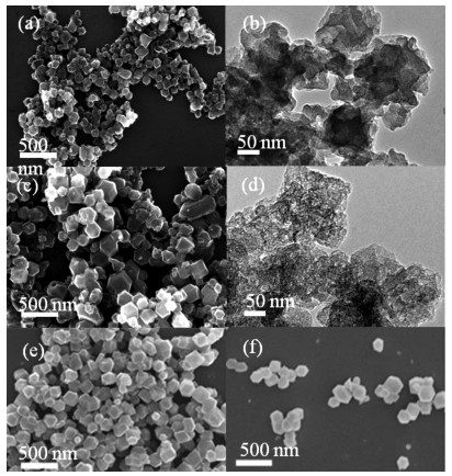
To investigate the micro-structure of NC and NMC-0.5 and confirm the activation effect of Na2SiO3, the SEM and TEM images were measured. Figs. 1a and c show the SEM image of NC and NMC-0.5, respectively, and both have an analogous dodecahedral shape, suggesting the ineffective effect of Na2SiO3 on morphology of ZIF-8. However, the diameter of NMC-0.5 (120 nm) is larger than that of NC (90 nm) due to the Na2SiO3 supporting during pyrolysis. The TEM images of NC is shown in Fig. 1b, revealing the microporous structure of the carbonized ZIF-8. On the contrary, the NMC-0.5 shows richer porous structure as shown in Fig. 1d, confirming the activation of Na2SiO3 for improving porosity. The SEM tested on NMC-0.3 (Fig. 1e) and NMC-1 (Fig. 1f) with the different amount of Na2SiO3, and the results showed that NMC-0.3 and NMC-1 still maintain a dodecahedral structure. Na2SiO3 does not affect the morphology of ZIF-8.

|
Download:
|
| Fig. 1. SEM and TEM images of (a, b) NC and (c, d) NMC-0.5. SEM images of (e) NMC-0.3 and (f) NMC-1. | |
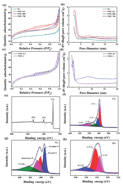
The N2 adsorption and desorption measurement were used to investigate the pore structure difference of NC and NMC samples. The N2 adsorption and desorption isotherm of NC (Fig. 2a) exhibits the typical type I. The low pressure region rises due to the inherent microporous structure of the ZIF-8 precursor, and the vertical tail is at a relative pressure of about 0.9-1.0, which relates to the pores piled up by the nanoparticles. On the contrary, NMC with different pyrolysis temperature shows N2 adsorption and desorption isotherms with similar type IV, indicating their mesoporous features due to the activation of Na2SiO3. Furthermore, the NMC with pyrolysis temperature of 900 ℃ shows an obvious hysteresis loop in the range of 0.45-0.9 of P/P0, indicating the 900 ℃ is the suitable temperature to create mesoporous structure. As shown in Fig. 2b, the pore size distributions were obtained by the BJH method from the desorption branch of the isotherms, which indicates that the NMC maintains pores between 2-3 nm.

|
Download:
|
| Fig. 2. N2 adsorption-desorption isotherms of (a, c) NC and NMC. (b, d) Pore size distributions of NMC series. (e) XPS spectra of NMC-0.5. The curve fitting of (f) C 1s, (g) N 1s and (h) O 1s. | |
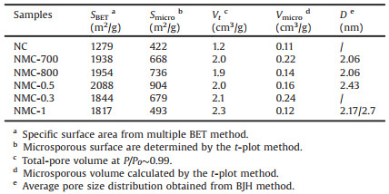
In general, the amount of activator is an important factor affecting its pore properties. The isotherms of NMC obtained by different mass ration of ZIF-8 to Na2SiO3 (NMC-0.3 and NMC-1) with pyrolysis temperature of 900 ℃ shows a type Ⅳ hysteresis loop (Fig. 2c), indicating their mesoporous structure like NMC-0.5. Fig. 2d shows that the pore size distribution is related to the amount of Na2SiO3, in which the NMC-0.3 not shows obvious mesoporous sizes indicating the ineffective activation due to the much little Na2SiO3. The detailed parameters of NMC series are shown in Table 1 and the NMC-0.5 presets the highest surface area, which shows the mass rate of ZIF-8 to Na2SiO3 of 0.5 is the suitable dosage of activator.
|
|
Table 1 The detail textural parameters of NMC. |
ZIF-8 is an excellent nitrogen precursor due to the utilization of the matching species 2-methylimidazole, which results to high nitrogen content for ZIF-derived carbon in-situ. XPS measurement was performed to probe the chemical composition and the content of nitrogen in the NMC-0.5 (Fig. 2e). The results showed that carbon, nitrogen and oxygen were detected at levels of 87.82, 8.19, and 3.99 wt%, respectively. For C 1s peak (Fig. 2f) can be deconvoluted into four peaks representing C=C (284.6 eV), C-N (285.3 eV), C-O (287.1 eV) and C=O (289.4 eV). NMC-0.5 includes several types of N-containing functional groups that can be identified by the bonding state of the N atoms in the complex. The high-resolution N 1s spectrum (Fig. 2g) shows the presence of pyridinic-N (398.6 eV), pyrrolic-N (400.2 eV), quaternary-N (401.3 eV) and oxidized-N (404.2 eV). For O 1s, as shown in Fig. 2h, the binding energies around 531.0 eV, 532.6 eV, and 536.0 eV represent C=O groups, C-O-C groups and O-C=O groups, respectively.
To compare the electrochemical performance of NMC and NC, CV and GCD tests were performed using a three-electrode system in a 6 mol/L KOH electrolyte. As shown in Fig. 3a, NC and NMC all exhibit typical rectangular curves at 5 mV/s, indicating an ideal EDLC storage behavior due to the mesoporous carbon electrode. The GCD curves of NC and NMC are symmetric triangles (Fig. 3b), indicating that they have superior performance as supercapacitors. According to the discharge time of GCD, it can be observed that the specific capacitance of NMC-0.5 is significantly higher than others, which is attributed to the reasonable pore size distribution and high surface area of NMC-0.5. When the current density was 0.5 A/g, the specific capacitance of NMC-0.5 was as high as 272 F/g. In addition, the nitrogen present in the carbon framework may cause pseudo-capacitance, but there is no obvious redox peak in the CV curve, indicating that the EDLC is the main source of capacitance.

|
Download:
|
| Fig. 3. (a) CV curves tested at 5mV/s of NMC and NC. (b) GCD curves tested at density of 0.5 A/g of NMC and NC. (c) Nyquist plot of NMC-0.5 and NC. (d) CV curves tested at 10-200mV/s of NMC-0.5. (e) GCD curves tested at 1-10 A/g of NMC-0.5. (f) Specific capacitances at different GCD current density. (g) Cycle life test of the NMC-0.5 with a three-electrode system at current density of 5 A/g. | |
Fig. 3c shows a Nyquist plot of the NC and NMC-0.5 at the frequency ranging from 10-2 Hz to 105 Hz in an open-circuit voltage. It mainly consists of high-frequency semicircle and low-frequency Warburg region, which corresponded to the charge transfer limiting process and the diffusion-limiting electrode process, respectively [44, 45]. The high frequency semicircle indicates a charge transfer resistance (Rct) and compared with the Rct of NC (0.71 Ω), the lower Rct of NMC-0.5 of 0.4 Ω exhibits its good electron conductivity due to the rich mesoporous structure [46].
The electrochemical performance of the NMC-0.5 was further evaluated by CV with different scan rate and GCD with different current density in the three-electrode system. The CV curve was tested at its working potential by varying the scan rate from 10-200 mV/s as shown in Fig. 3d. The CV curves for the NMC-0.5 exhibit a good rectangular shape even at the scan rate up to 200mV/s, indicating that NMC-0.5 achieves good diffusion in pores and good ion transmission behavior [47]. Further GCD test recorded the triangular profile and confirmed excellent electrochemical capacitance performance (Fig. 3e), and the specific capacitance of NMC-0.5 was determined to be 263 F/g at a current density of 1 A/g. It is worthy to note that the excellent capacitance retentions (71.6%) are achieved over the NMC-0.5 at a high current density of 10 A/g (Fig. 3f). The capacitance of NMC-0.5 is higher than many other materials as seen in Fig. 3f [47-57]. The cycling stability of NMC-0.5 was measured by GCD at 5 A/g. The GCD curves remained unchanged without any distortion after 10, 000 cycles (96.07%), indicating the excellent cycling stability (Fig. 3g).
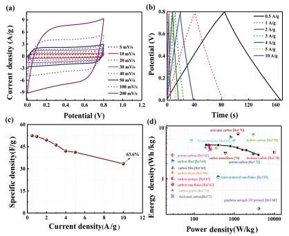
Electrochemical performance was evaluated in a two-electrode system used in practical applications commonly. Therefore, a two-electrode symmetric supercapacitor was assembled using NMC-0.5 as the electrode. Fig. 4a shows the CV curve recorded for the NMC-0.5 from a potential window of 0 to 0.8 V at different scan rates. Noticeably, when the scan rate was varied from 5 to 200 mV/s, the CV curve maintained a quasi-rectangular shape, which means that the NMC-0.5 electrode has excellent rate capability. The GCD curves of NMC-0.5 with different current densities ranging from 0.5 A/g to 10 A/g was measured (Fig. 4b). The triangular curve presents a typical linear discharge curve, indicating that the electrode of NMC-0.5 had excellent electrochemical reversibility, due to that the charge storage equilibrium of the symmetrical device. At a current density of 0.5 A/g, the specific capacitance was as high as 52.4 F/g, and when the current density was increased to 10 A/g, the specific capacitance reached a high of 33.4F/g (Fig. 4c). Moreover, the Ragone plots (Fig. 4d) confirmed the electrochemical performance of NMC-0.5 electrode materials. The results show that the energy density of the NMC-0.5 based supercapacitor was 4.66 Wh/kg at a power density of 0.21 kW/kg, and the energy density remains at 2.97 Wh/kg as the power density increases to 0.4 kW/kg, and the performance of the symmetrical system is superior to that of a typical carbon nanomaterial-based supercapacitor, especially, ZIF-derived carbon materials [58-74], confirming the positive effect of mesoporous structure in ZIF-derived carbon materials.

|
Download:
|
| Fig. 4. (a) CV curves tested at scan rate of 5-200 mV/s of NMC-0.5. (b) GCD curves tested at current density of 0.5-10 A/g of NMC-0.5. (c) Specific capacitances at different GCD. (d) Ragone plots comparison with the reported porous carbon materials. | |
In summary, ZIF-derived mesoporous carbon particles have been prepared by simple grinding of ZIF-8 with Na2SiO3 and the subsequently pyrolysis process. Solid-solid grinding provides a solvent free condition, which is environmentally friendly. The low-cost Na2SiO3 acted activatior and prevented carbon shrinkage of ZIF-8 during pyrolysis to increase carbon residue, created mesoporous on NMC, and retain the dodecahedron structure of ZIF-8. Moreover, the pyrolysis temperature and mass ratio of Na2SiO3 to ZIF-8 were affected the porous features of NMC. When the mass ratio of sodium silicate to ZIF-8 powder is 0.5 and pyrolysis temperature is 900 ℃, NMC has a better activation effect. The resultant optimum NMC-0.5 featured with high specific surface area 2088 m2/g, mesoporous distribution at 2.43 nm and certain of nitrogen doping. As electrode in supercapacitor, the NMC displayed high electrochemical capacitance and good stability, which showed potential in energy-storage applications.
Declaration of competing interestThe authors report no declarations of interest.
AcknowledgmentsWe thank the National Natural Science Foundation of China (No. 21676070), Hebei Province Introduction of Foreign Intelligence Projects (2018), Beijing National Laboratory for Molecular Sciences, Hebei Science and Technology Project (Nos. 20544401D, 20314401D), Tianjin Science and Technology Project (No. 19YFSLQY00070), CAS Key Laboratory of Carbon Materials (No. KLCMKFJJ2007), Hebei Province 2020 Central Leading Local Science and Technology Development Fund Project (No. 206Z4406G).
| [1] |
B.S. Gou, Y.Y. Yang, Z.G. Hu, et al., Electrochim. Acta 223 (2017) 74-84. DOI:10.1016/j.electacta.2016.12.012 |
| [2] |
Z.P. Qiu, Y.S. Wang, X. Bi, et al., J. Power Sources 376 (2018) 82-90. DOI:10.1016/j.jpowsour.2017.11.077 |
| [3] |
Y. Zhang, J. Liu, S.L. Li, Z.M. Su, Y.Q. Lan, Energy Fuels 1 (2019) 100021. |
| [4] |
L. Jin, H. Pang, Chin. Chem. Lett. 31 (2020) 2300-2304. DOI:10.1016/j.cclet.2020.03.041 |
| [5] |
H.J. Zhou, X.X. Li, Y. Li, M.B. Zheng, H. Pang, Nano-Micro Lett. 11 (2019) 46-78. DOI:10.1007/s40820-019-0280-2 |
| [6] |
S.A. Dong, X.J. He, H.F. Zhang, et al., J. Mater. Chem. A 6 (2018) 15954-15960. DOI:10.1039/C8TA04080J |
| [7] |
J.G. Wang, H.Z. Liu, H.H. Sun, et al., Carbon 127 (2018) 85-92. DOI:10.1016/j.carbon.2017.10.084 |
| [8] |
A.J. Amali, J.K. Sun, Q. Xu, Chem. Commun. 50 (2014) 1519-1522. DOI:10.1039/C3CC48112C |
| [9] |
Y.C. Yao, H.L. Wu, L. Huang, et al., Electrochim. Acta 246 (2017) 606-614. DOI:10.1016/j.electacta.2017.06.094 |
| [10] |
J.Q. Zhou, M. Wang, X. Li, J. Porous Mater. 26 (2019) 99-108. DOI:10.1007/s10934-018-0622-3 |
| [11] |
T. Panja, D. Bhattacharjya, J.S. Yu, J. Mater. Chem. A 3 (2015) 18001-18009. DOI:10.1039/C5TA04169D |
| [12] |
H.J. Zhou, M.B. Zheng, H. Tang, et al., Small 16 (2020) 1904252. DOI:10.1002/smll.201904252 |
| [13] |
J.F. Li, Q.S. Wu, Chem. Phys. Lett. 691 (2018) 238-242. DOI:10.1016/j.cplett.2017.11.031 |
| [14] |
S. Wang, T. Wang, P.C. Liu, et al., Mater. Res. Bull. 88 (2017) 62-68. DOI:10.1016/j.materresbull.2016.11.039 |
| [15] |
J. Du, L. Liu, Y.F. Yu, et al., Nanoscale 11 (2019) 4453-4462. DOI:10.1039/C8NR08784A |
| [16] |
Y.T. Gong, Z.Z. Wei, J. Wang, et al., Sci. Rep. 4 (2014) 6349. |
| [17] |
S. Giri, D. Ghosh, A. Mandal, C.K. Das, Macromol. Symp. 327 (2013) 54-63. DOI:10.1002/masy.201350506 |
| [18] |
J.L. Zhuang, X.Y. Liu, H.L. Mao, et al., J. Power Sources 429 (2019) 9-16. DOI:10.1016/j.jpowsour.2019.04.112 |
| [19] |
L. Xiang, A. Ali, R. Jamal, et al., Polym. Compos. 40 (2019). |
| [20] |
C.L. Jiang, G.A. Yakaboylu, T. Yumak, et al., Renewa. Energy 155 (2020) 38-52. DOI:10.1016/j.renene.2020.03.111 |
| [21] |
G.X. Lin, R.G. Ma, Y. Zhou, et al., Electrochim. Acta 261 (2018) 49-57. DOI:10.1016/j.electacta.2017.12.107 |
| [22] |
X.Q. Yang, D.C. Wu, X.M. Chen, R.W. Fu, J. Phys. Chem. C 114 (2010) 8581-8586. |
| [23] |
R. Zeng, H.R. Deng, Y.B. Xiao, et al., Compos. Commun. 10 (2018) 73-80. DOI:10.1016/j.coco.2018.07.002 |
| [24] |
Y. Li, Y.Y. Shan, H. Pang, Chin. Chem. Lett. 31 (2020) 2280-2286. DOI:10.1016/j.cclet.2020.03.027 |
| [25] |
R.R. Salunkhe, Y. Kamachi, N.L. Torad, et al., J. Mater. Chem. A 2 (2014) 19848-19854. DOI:10.1039/C4TA04277H |
| [26] |
Z.B. Liang, R. Zhao, T.J. Qiu, R.Q. Zou, Q. Xu, Energy Fuels 1 (2019) 100001. |
| [27] |
C.N. Gu, J.J. Li, G. Yang, et al., Chin. Chem. Lett. 31 (2020) 2263-2267. DOI:10.1016/j.cclet.2020.02.044 |
| [28] |
D.D. Li, H.Q. Xu, L. Jiao, H.L. Jiang, Energy Fuels 2 (2019) 100005. |
| [29] |
M. Jiang, X.P. Gao, D.D. Zhu, Y.X. Duan, J.M. Zhang, Electrochim. Acta 196 (2016) 699-707. DOI:10.1016/j.electacta.2016.02.094 |
| [30] |
T. Gao, H.B. Li, F. Zhou, et al., Desalination 451 (2019) 133-138. DOI:10.1016/j.desal.2017.06.021 |
| [31] |
X.T. Xu, M. Wang, Y. Liu, et al., Energy Storage Mater. 5 (2016) 132-138. DOI:10.1016/j.ensm.2016.07.002 |
| [32] |
Z.Y. Tang, G.H. Zhang, H. Zhang, et al., Energy Storage Mater. 10 (2018) 75-84. DOI:10.1016/j.ensm.2017.08.009 |
| [33] |
W.N. Zhang, Y.Y. Liu, G. Lu, et al., Adv. Mater. 27 (2015) 2923-2929. DOI:10.1002/adma.201405752 |
| [34] |
Z.C. Zhang, Y.F. Chen, X.B. Xu, et al., Angew. Chem. Int. Ed. 53 (2014) 429-433. DOI:10.1002/anie.201308589 |
| [35] |
S. Zhong, C.X. Zhan, D.P. Cao, Carbon 85 (2015) 51-59. DOI:10.1016/j.carbon.2014.12.064 |
| [36] |
L. Shang, H.J. Yu, X. Huang, et al., Adv. Mater. 28 (2016) 1668-1674. DOI:10.1002/adma.201505045 |
| [37] |
F.F. Wang, L.K. Zhu, Y. Pan, et al., Inorg. Chem. Front. 6 (2019) 32-39. |
| [38] |
X.Y. Hu, X.L. Yan, M. Zhou, S. Komarneni, Microporous Mesoporous Mater. 219 (2015) 311-316. |
| [39] |
J.X. Li, K.H. Han, J.H. Qi, et al., J. Mater. Sci: Mater. Electron. 30 (2019) 19415-19425. DOI:10.1007/s10854-019-02303-y |
| [40] |
H. Wang, L. Li, C.L. Wang, et al., J. Inorg. Mater. 32 (2017) 1181-1187. DOI:10.15541/jim20170049 |
| [41] |
X.Q. Yang, W. Chen, H.D. Bian, et al., Chem. Eur. J. 24 (2018) 11185-11192. DOI:10.1002/chem.201801869 |
| [42] |
N.L. Torad, M. Hu, Y. Kamachi, et al., Chem. Commun. 49 (2013) 2521-2523. DOI:10.1039/c3cc38955c |
| [43] |
Y.H. Li, X.H. Cai, S.J. Chen, et al., ChemSusChem 11 (2018) 1040-1047. DOI:10.1002/cssc.201800016 |
| [44] |
M. Liu, Y.F. Yu, B.B. Liu, et al., J. Alloys. Compd. 768 (2018) 42-48. DOI:10.1016/j.jallcom.2018.07.234 |
| [45] |
J.G. Wang, H.Z. Liu, H.H. Sun, et al., Carbon 127 (2018) 85-92. DOI:10.1016/j.carbon.2017.10.084 |
| [46] |
Y.L. Song, W. Li, Z. Xu, et al., SN Appl. Sci. 1 (2019) 122. DOI:10.1007/s42452-018-0132-6 |
| [47] |
S. Yaglikci, Y. Gokce, E. Yagmur, Z. Aktas, Environ. Technol. 41 (2019) 36-48. |
| [48] |
K.L. Wang, Y.H. Cao, X.M. Wang, et al., Energy 94 (2016) 666-671. DOI:10.1016/j.energy.2015.10.047 |
| [49] |
J. Zhou, H. Wang, W. Yang, S.J. Wu, W. Han, Carbohydr. Polym. 198 (2018) 364-374. DOI:10.1016/j.carbpol.2018.06.095 |
| [50] |
J.G. Li, Y.F. Ho, M.M.M. Ahmed, H.C. Liang, S.W. Kuo, Chem. Eur. J. 25 (2019) 10456-10463. DOI:10.1002/chem.201901724 |
| [51] |
X. Yang, Z.H. Jiang, B.H. Fei, J.F. Ma, X.G. Liu, Electrochim. Acta 282 (2018) 813-821. DOI:10.1016/j.electacta.2018.06.131 |
| [52] |
M.X. Liu, F.L. Zhao, D.Z. Zhu, et al., Mater. Chem. Phys. 211 (2018) 234-241. DOI:10.1016/j.matchemphys.2018.02.030 |
| [53] |
W.J. Lu, X.H. Cao, L.N. Hao, Y.P. Zhou, Y.W. Wang, Mater. Lett. 264 (2020) 127339. DOI:10.1016/j.matlet.2020.127339 |
| [54] |
H.C. Jung, R. Vinodh, C.V.V. Muralee Gopi, M. Yi, H.J. Kim, Mater. Lett. 257 (2019) 126732. DOI:10.1016/j.matlet.2019.126732 |
| [55] |
X.X. Qu, Y.H. Liu, C.X. Zhang, et al., J. Mater. Sci: Mater. Electron. 30 (2019) 7873-7882. DOI:10.1007/s10854-019-01107-4 |
| [56] |
S. Natarajan, M. Ulaganathan, H.C. Bajaj, ChemElectroChem 6 (2019) 5283-5329. DOI:10.1002/celc.201901448 |
| [57] |
H. Chen, Z.Z. Zhao, P.R. Qi, Int. J. Nanomanuf. 15 (2019) 181-195. DOI:10.1504/IJNM.2019.097253 |
| [58] |
Y.N. Gong, D.L. Li, C.Z. Luo, Q. Fu, C.X. Pan, Green Chem. 19 (2017) 4132. DOI:10.1039/C7GC01681F |
| [59] |
T. Zhai, X.H. Lu, H.Y. Wang, et al., Nano Lett. 15 (2015) 3189-3194. DOI:10.1021/acs.nanolett.5b00321 |
| [60] |
S. Wang, B. Pei, X. Zhao, R.A.W. Dryfe, Appl Nano Energy 2 (2013) 530-536. DOI:10.1016/j.nanoen.2012.12.005 |
| [61] |
K. Karuppasamy, K. Prasanna, P. Robert Ilango, et al., J. Ind. Eng. Chem. 80 (2019) 258-264. DOI:10.1016/j.jiec.2019.08.003 |
| [62] |
S.S. Pujari, S.A. Kadam, Y.R. Ma, et al., J. Electron. Mater. 49 (2020). DOI:10.1007/s11664-020-08095-w |
| [63] |
S.M. Nandhini, M. Gopalan, Appl. Surf. Sci. 480 (2019) 186-198. DOI:10.1016/j.apsusc.2019.02.250 |
| [64] |
S.J. Patil, J.H. Kim, D.W. Lee, Chem. Eng. J. 322 (2017) 498-509. DOI:10.1016/j.cej.2017.03.095 |
| [65] |
S.J. Patil, J.H. Kim, D.W. Lee, J. Power Sources 342 (2017) 652-665. DOI:10.1016/j.jpowsour.2016.12.096 |
| [66] |
J.A. Argüello, A. Cerpa, R. Moreno, Ceram. Int. 45 (2019) 14316-14321. DOI:10.1016/j.ceramint.2019.04.145 |
| [67] |
Z. Rui, J. Xiangxia, C. Yanting, et al., J. Mater. Chem. A 6 (2018) 17730-17739. DOI:10.1039/C8TA06471G |
| [68] |
C. Zhu, T.Y. Liu, F. Qian, et al., Nano Lett. 16 (2016) 3448-3456. DOI:10.1021/acs.nanolett.5b04965 |
| [69] |
Y.F. Wang, B.W. Chen, Y. Zhang, et al., Electrochim. Acta 213 (2016) 260-269. DOI:10.1016/j.electacta.2016.07.019 |
| [70] |
X.H. Yuan, B.W. Chen, X.W. Wu, et al., Chin. J. Chem. 35 (2017) 61-66. DOI:10.1002/cjoc.201600212 |
| [71] |
H. Azhan, K. Azman, O.H. Hassan, et al., Mater. Sci. Forum. 846 (2016) 545-550. DOI:10.4028/www.scientific.net/MSF.846.545 |
| [72] |
R. Zhang, X.X. Jing, Y.T. Chu, et al., J. Mater. Chem. A 6 (2018) 17730-17739. DOI:10.1039/C8TA06471G |
| [73] |
Z.Q. Ye, F.J. Wang, C. Jia, Z.Q. Shao, J. Mater. Sci. 53 (2018) 12374-12387. DOI:10.1007/s10853-018-2487-x |
| [74] |
Y. Liu, J. Zhou, L. Chen, et al., ACS Appl. Mater. Interfaces 2 (2015) 23515-23520. |