 2021, Vol. 32


b Beijing National Laboratory for Molecular Sciences, CAS Key Laboratory of Organic Solids, Institute of Chemistry, Chinese Academy of Sciences, Beijing 100190, China;
c School of Chemical Science, University of Chinese Academy of Sciences, Beijing 100049, China;
d School of Chemistry and Chemical Engineering, Guizhou University, Guiyang 550025, China;
e MOE Key Laboratory of Low-grade Energy Utilization Technologies and Systems, CQU-NUS Renewable Energy Materials & Devices Joint Laboratory, School of Energy & Power Engineering, Chongqing University, Chongqing 400044, China;
f Department of Energy Engineering, School of Energy and Chemical Engineering, Low Dimensional Carbon Materials Center, Ulsan National Institute of Science and Technology (UNIST), Ulsan 689-798, South Korea;
g Guangzhou Polyforte Chemical Technology Co. Ltd., Guangzhou 510520, China
As hopeful clean and renewable energy sources, organic solar cells (OSCs) are suitable for low-cost solution processing technology and have some unique advantages, such as light weight, flexibility, printability and so on [1-5]. Noteworthy development has been made in the progress of novel and efficient high-performance OSCs materials and continuously optimized technology on the device fabrication. In recent five years, the significant improvement of OSCs power conversion efficiency (PCE) has been achieved by employing the wide-bandgap p-type conjugated polymers as donor and the narrow-bandgap n-type small molecule acceptors (SMAs) [6-10]. Compared with traditional OSCs based on fullerene acceptor, the SMAs have the remarkable merits of suitable and tunable electronic energy levels, adjustable chemical structures, high absorption in visible–NIR region, and good morphology stability. Very recently, the single junction OSCs with the SMAs have boosted PCE to over 17%, which reached the threshold for application [11-13].
Indacenodithiophene (IDT) derivatives are kinds of the most representative and widely used cores of SMAs [7, 14-18]. In IDT acceptors system, there is a general rule that smaller cores increase the ionization energy and blue-shift the absorption, which lead to the poorer π-π stacking. In addition, the side-chain and end groups are the key factors to influence the optical, electrochemical and photovoltaic properties of SMAs. The first report of IDT-based SMA, IDIC and its diverse structural variants have showed potential in various applications of OSCs, including high-efficiency binary, ternary bulk junction (BHJ) and tandem OSCs [19-26].
There are three components in the SMAs: fused-ring electron-donating core, electrophilic end group and extended side chains. Therefore, in order to obtain the adjustable energy levels, π-π stacking, crystallinity and spectral absorption etc., the most effective way is to modify the three parts structures [14-26]. It is well known that the fluorination of the end groups for the SMAs could result in optical bandgap decrease (absorption redshift), electron affinity and electron mobility increase compared with fluoride-free or mono/di-methylation of the end groups [27-32]. Meanwhile, fluorination is an efficient strategy to improve theπ-π stacking and crystallinity, thus regulate the morphology to get high fill factor and device performance reasonably [33-35]. Fluorination in SMAs showed good application prospects in different kinds of OSCs, hence it is necessary to further study the influence of fluorination density and position on the photovoltaic properties of the IDT-based NFAs.
We regulate the end-group fluorination density and position to verify the relationship between chemical structures and BHJ photovoltaic properties of an IDT-based SMA series, including IDIC, IDIC-2F and IDIC-4F (Fig. 1) [36, 37]. The photovoltaic performance of the IDIC-nF (n=0, 2, 4) acceptors are investigated by fabricating single-junction OSCs with the wide-bandgapp-type polymer poly[(thiophene)-alt-(6, 7-difluoro-2-(2-hexyldecyloxy)quinoxaline)] (PTQ10) [37, 38] as donor. The UV–vis spectroscopy, thermogravimetric analysis (TGA), cyclic voltammetry (CV), atomic force microscopy (AFM), grazing incidence wide-angle X-ray scattering (GIWAXS), space-charge limited current (SCLC) mobility measurements are performed to investigate the chemical structure-morphology-performance relationship of the PTQ10: IDIC-nF blend films. The results indicate that the number and position of the fluorination on the IDIC-nF acceptors influence their photovoltaic performance significantly, and the difluorinated IDIC-2F acceptor based OSCs achieve the highest PCE of 13%, benefitted from its higher Jsc and FF.

|
Download:
|
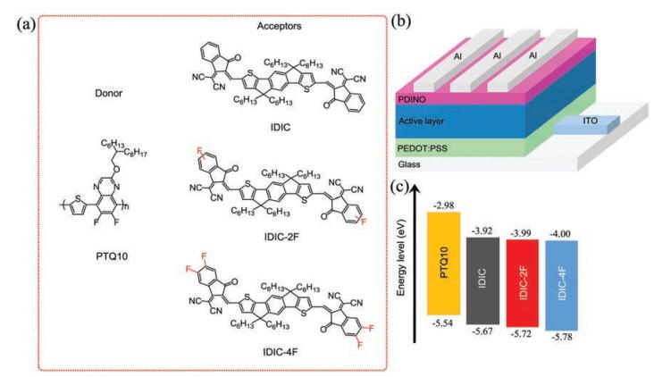
| Fig. 1. (a) Molecular structures of polymer donor PTQ10 and acceptors (IDIC, IDIC-2F, IDIC-4F). (b) Device structure used in this work. (c) Energy level diagram of the related materials used in the OSCs. | |
The molecular structures of PTQ10 donor and IDIC-nF (n=0, 2, 4) acceptors are shown in Fig. 1. Fig. 2 shows the synthetic routes of the IDIC-nF acceptors. One-pot reaction of compound 1 with IC, IC-1F and IC-2F easily generates the three different symmetrical SMAs: IDIC, IDIC-2F, and IDIC-4F (Scheme S1 in Supporting information). The detailed synthetic procedures were described in Supporting information. TGA measurement was employed to investigate the thermal stability of IDIC-nF, as seen in Fig. S1 (Supporting information). The results revealed that the end-group fluorination would enhance the thermal stability of the materials, and the decomposition temperatures (Td) at 5% weight-loss are 310 ℃, 350 ℃ and 350 ℃ for IDIC, IDIC-2F and IDIC-4F, respectively [39]. It indicates that all the three acceptors have good thermal stabilities for the OSCs fabrication.

|
Download:
|
| Fig. 2. Synthetic routes of IDIC, IDIC-2F and IDIC-4F. | |
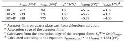
The UV–vis absorption spectra of the PTQ10 (for comparison) and IDIC-nF acceptor films are shown in Fig. S2a (Supporting information), and the optical absorption properties of IDIC-nF are summarized in Table 1. IDIC-2F and IDIC-4F acceptor films both present a main absorption peak at 719nm with absorption edge at about 775nm, which corresponds to an optical bandgap of about 1.60eV. Compared to fluoride-free acceptor IDIC, the fluorinated IDIC-nF generally red-shifts the absorption profile and λmax, resulting in lower optical bandgap than IDIC film (Egopt =1.63 eV). Fig. 1c shows the energy level diagram of the related materials calculated from the onset oxidation and reduction potentials measured by electrochemical cyclic voltammetry. Relative to the PTQ10 donor, the three IDIC analogue acceptors display reasonable energy level alignments. The highest occupied molecular orbital (HOMO) and the lowest unoccupied molecular orbital (LUMO) energies of IDIC-nF monotonically down-shift with increasing n, which is consistent with the electron-withdrawing effect of fluorine.
|
|
Table 1 Physicochemical properties of IDIC-nF (n = 0, 2, 4) acceptors. |
In order to evaluate the photovoltaic properties of the IDIC-nF acceptors, the OSCs with the conventional architecture (ITO/PEDOT: PSS/PTQ10:IDIC-nF/PDINO/Al) were fabricated. It should be mentioned that PDINO (perylene diimide functionalized with amino N-oxide) is a typical cathode interlayer, and PTQ10 was selected as donor because it possesses a suitable energy level and relatively low-cost synthesis. The fabrication condition of OSCs was optimized via controlling different donor/acceptor weight ratio, thermal annealing treatment and so on. The optimized conditions of OSCs are PTQ10:IDIC-nF (D/A) at weight ratio of 1:1 and thermal annealing at 140 ℃ (for IDIC-based OSC) or 120 ℃ (for IDIC-2F and IDIC-4F based OSC) for 5min [36-38]. The PTQ10: IDIC-nF blend active layers were spin-coated from chloroform solution without the use of any additives in nitrogen protected glove box.
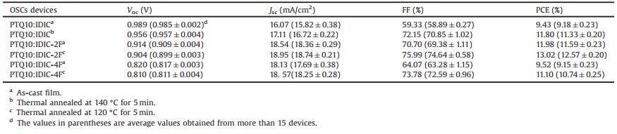
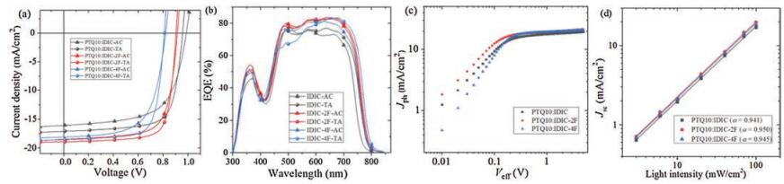
The current density–voltage (J–V) curves of the optimized OSCs based on PTQ10:IDIC-nF under air mass global (AM 1.5 G) simulated solar illumination is presented in Fig. 3a and the corresponding photovoltaic parameters are listed in Table 2. The devices based on PTQ10: IDIC without thermal annealing showed a PCE of 9.43% (Voc=0.989 V, Jsc =16.07 mA/cm2, FF=59.33%), and the PCE increased to 11.80% (Voc=0.956 V, Jsc =17.11mA/cm2, FF=72.15%) after 140 ℃ thermal annealing for 5 min, which matches the values reported in the literature [37]. Thermal annealing at 120 ℃ for 5min improved the PCE of the OSCs based on end-group fluorination acceptors from 11.98% (Voc=0.914 V, Jsc =18.54 mA/cm2, FF=70.70%) to 13.02% (Voc=0.904 V, Jsc = 18.95 mA/cm2, FF=75.99%) for IDIC-2F acceptor, and from 9.52% (Voc=0.820 V, Jsc = 18.13 mA/cm2, FF=64.07%) to 11.10% (Voc=0.810 V, Jsc = 18.57 mA/cm2, FF=73.78%) for IDIC-4F acceptor, respectively. It is clearly noted that the Voc decreases with increasing n (the number of fluorination) in IDIC-nF, which is consistent with the lower LUMO levels of IDIC-2F and IDIC-4F. Meanwhile, the Jsc values increase from 17.11 mA/cm2 for the OSC based on IDIC acceptor to 18.57–18.95 mA/cm2 for OSCs with the fluorinated acceptors, benefitted from their lower optical bandgap and broader absorption. The results of Jsc trends are coincident with the external quantum efficiency (EQE) spectra (Fig. 3b). The FF values of ~72%−73% for the IDIC-nF based OSCs are very similar, except for the IDIC-2F-based OSCs with the highest FF of ~75%. Due to the advantages of Jsc and FF as well as acceptable Voc, the IDIC-2F-based OSCs achieve the highest PCE of 13%.

|
Download:
|
| Fig. 3. Photovoltaic performance of the OSCs based on PTQ10: acceptors. (a) J-V curves of the traditional structured OSCs based on PTQ10: acceptors (1:1, w/w), under the illumination of AM1.5 G, 100 mW/cm2. (b) EQE spectra of the corresponding OSCs. (c) Jph versus Veff curves of the optimized devices. (d) Light intensity dependence of Jsc. | |
|
|
Table 2 Device performance of the OSCs based on PTQ10: IDIC-nF (1:1, w/w) under AM 1.5 G 100 mW/cm2 illumination. |
It is important to develop the photovoltaic materials that tolerate thickness variations of the BHJ active layer for large-scale and printable manufacturing of OSCs [40]. Therefore, the active layer thickness dependence of the OSCs performance of the PTQ10: IDIC-2F based OSCs was investigated, and the active layer thickness changed from 80 nm to 354nm. The plots of photovoltaic performance versus active layer thickness are shown in Fig. S3 (Supporting information) and photovoltaic parameters of the corresponding OSCs are presented in Table S1 (Supporting Information). The Voc and FF values reveal a decreasing tendency with the increase of active layer thickness, and the downward trend of FF is more obvious, while the Jsc value of the OSCs increases with the increase of the active layer thickness. The OSC reached the highest PCE of 13.02% with the active layer thickness at 120 nm. It is necessary to mention that the PCE of the OSCs based on PTQ10: IDIC-2F still keep high values of 12.00% and 11.46% with active layer thickness of 80 and 354 nm, respectively. The thickness-insensitive PCE of the OSCs verifies that the PTQ10: IDIC-2F OSCs have potential for large-scale and printable fabrication technology.
In order to systematically study the exciton dissociation and charge collection behavior of the OSCs with different SMAs, the dependence of photocurrent density (Jph) versus the effective voltage (Veff) of the optimized devices was measured. Fig. 3c shows the Jph versus Veff plot of the OSCs, where Jph is defined as JL−JD and Veff is defined as V0−Vbias. JL and JD are the photocurrent densities under illumination and in the dark condition, and V0 is the voltage at which Jph=0 and Vbias is the applied bias [41, 42]. The charge dissociation probability P(E, T) can be calculated from the value ofJph/Jsat, where Jsat is the saturated Jph value when Veff ≥ 2V. Under the short circuit condition, the P(E, T) value are 96.32% for the IDIC, 97.78% for IDIC-2F and 97.19% for IDIC-4F based OSCs, respectively. In general, the highest P(E, T) values of the IDIC-2F based OSCs represent the efficient exciton dissociation and charge collection. Steady state photoluminescence (PL) quenching experiment was carried out to confirm the exciton dissociation and charge transfer behavior in the blends. As shown in Fig. S4 (Supporting information), comparison to neat PTQ10 film, PL spectroscopy of all the three blend films show quenching efficiencies of over 99%, indicating effective exciton dissociation and charge transfer between PTQ10 and IDIC-nF, thus resulting in the high FF [43-45].
To further illustrate the charge carrier recombination behavior in the OSCs with the different SMAs, the dependence of Jsc on light intensity (Plight) was measured. The relationship of Jsc and Plight can be described by the formula of Jsc∝(Plight)α, where α is a parameter related to the recombination degree [46-48]. If the value of α approaches 1, bimolecular recombination in the BHJ blend films could be ignored. As seen in Fig. 3d, the index α is 0.941, 0.950 and 0.945 for the IDIC, IDIC-2F and IDIC-4F based OSCs, respectively (Fig. 3d). The results of α value illustrate that less bimolecular recombination occur in the IDIC-2F based OSC device compared with the IDIC and IDIC-4F based OSCs.
The electron mobility (μe) and hole mobility (μh) of the PTQ10: IDIC-nF active layers were measured using the space-charge limited current (SCLC) method [49]. The structure of electron-only and hole-only devices are ITO/ZnO/PTQ10: IDIC-nF/PDINO/Al and ITO/PEDOT: PSS/PTQ10: IDIC-nF/MoO3/Ag, respectively. Fig. S5 (Supporting information) shows the plots of the measurement results, and the obtained μe and μh values of the PTQ10:IDIC-nF active layers and the polymer and SMA pure films are listed in Table S2. The electron mobilities of IDIC-nF are 5.64×10⁻⁴ cm2 V-1 s-1 for IDIC, 1.67×10⁻³ cm2 V-1 s-1 for IDIC-2F and 1.08×10⁻³ cm2 V-1 s-1 for IDIC-4F. Among the IDIC-nF, IDIC-2F has the highest electron mobility which is comparable to the SMFs used for the most efficient OSCs [13]. The electron mobilities of the blend active layers of the acceptor with PTQ10 donor are in the range of 6.16–8.96×10⁻⁴ cm2 V-1 s-1. For the PTQ10-based OSCs without any post-treatment, the μh/μe ratios are 0.09, 0.15 and 0.11 for the IDIC, IDIC-2F and IDIC-4F-based devices respectively. After thermal annealing under corresponding conditions for 5min, theμh/μe ratios of the corresponding OSCs increase to 0.13, 0.16 and 0.15 respectively. The OSCs based on IDIC-2F show the most balanced charge mobility with μh/μe of 0.15 and 0.16 for the devices without and with thermal treatment, which could be one reason for the higher PCE of 11.98% (as-cast device) and 13.02% (thermal annealing device) for the IDIC-2F based OSCs.
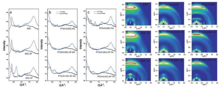
To investigate the end-group fluorination effects on aggregation morphologies of active layers, the atomic force microscopy (AFM), and transmission electron microscopy (TEM) measurements were conducted [50, 51]. Grazing incident wide-angle X-ray diffraction (GIWAXS) measurement was also performed to further investigate the molecular orientation and packing behavior in solid state. The plots and 2D patterns of GIWAXS measurement are displayed in Fig. 4 and Tables S3 and S4 (Supporting information). According to the 2D patterns, all neat IDIC, IDIC-2F and IDIC-4F acceptor films show predominant face-on orientation, mainly due to their similar skeletal structures. In the corresponding line-cuts, the neat IDIC film exhibits the (010) π-π stacking distance of 3.523 Å and coherence length of 31.821 Å in the out-of-plane (OOP) direction. With increasing the fluorination substitutions in the end-groups, the OOP (010) π-π stacking distance and coherence length values are 3.507 Å and 49.438 Å for neat IDIC-2F film and 3.570 Å and 57.224 Å for neat IDIC-4F film, respectively. It is noted that the neat IDIC-2F film presents the tightestπ-π stacking with moderate coherence length value. Upon blending with the PTQ10 donor polymer, the OOP π-π stacking coherence length values of all three blend films are comparable. After TA treatment, compared to the coexistence of face-on and edge-on orientation in PTQ10: IDIC blend film, the favorable face-on orientation was mostly retained in both PTQ10: IDIC-2F and PTQ10: IDIC-4F films, which is desirable for the vertical charge transport in devices. Especially, the PTQ10: IDIC-2F blend film shows closer OOP (010) π-π stacking, indicating the suitable miscibility between donor and acceptor components in blend, which benefits for the exciton dissociation and charge transfer in devices [52-54]. The improvement of molecular packing could be beneficial for the higher performance of the OSCs with the TA treatment. Meanwhile, the results are correlated well with the device performances mentioned above.

|
Download:
|
| Fig. 4. 1D line-cuts and 2D patterns of the GIWAXS measurements. (a) Neat acceptor films, (b) as cast PTQ10:acceptor blend films and (c) thermal annealed PTQ10:acceptor blend films. (d, g, j) GIWAXS patterns of three acceptor films, (e, h, k) GIWAXS patterns of as cast PTQ10: acceptor blend films. (f, i, l) GIWAXS patterns of thermal annealed PTQ10: IDIC-nF acceptor blend films. The sample names are labeled on the figures. | |
Fig. S6 (Supporting information) presents the AFM images of PTQ10: IDIC-nF blend films, and the relatively uniform morphology and smooth surface with a root-mean-square (RMS) roughness of 0.89 nm for IDIC, 0.87 nm for IDIC-2F and 1.27 nm for IDIC-4F. Fig. S7 (Supporting information) shows the TEM images of PTQ10: IDIC-nF blend films. The obviously refined fibrillary networks are found in all the PTQ10: IDIC-nF blend films both in as-cast and thermal annealed films. The domain size decreases with the increase of n of IDIC-nF SMAs after thermal annealing treatment. From corresponding relationship between devices performance and domain size, too large or too small domain sizes are not beneficial for the efficient exciton dissociation and charge transport. The AFM and TEM results all indicate that an appropriate phase separation and domain size are useful to improve devices performance.
In conclusion, in order to study the fluorination effects on IDT-based SMAs, three IDT-based SMA series IDIC-nF are designed and synthesized with n=0, 2, 4 fluorine atom(s). The absorption edge of IDIC-nF red-shifts with the improved π-π stacking and crystallinity, and the energy level of IDIC-nF downshifts with increasing n. Due to the higher Jsc and FF as well as acceptable Voc, the difluorinated IDIC-2F acceptor based OSCs achieve the highest PCE of 13% in comparison with the OSC devices based on IDIC and IDIC-4F. And the photovoltaic performance of the OSCs based on PTQ10: IDIC-2F is insensitive to the active layer thickness: PCE of the PTQ10: IDIC-2F OSCs still keep high values of 12.00% and 11.46% with active layer thickness of 80 and 354 nm, respectively. The results indicate that fine and delicate modulation of SMAs molecular structure is an effective way to improve photovoltaic performance of the OSCs.
Declaration of competing interestThe authors declare that they have no known competing financial interests or personal relationships that could have appeared to influence the work reported in this paper.
AcknowledgmentsThe work was supported by the Natural Science Foundation of China (Nos. 51820105003, 51863002 and 51973042), Excellent young scientific and technological talents of Guizhou, China (No. QKHPTRC [2019]5652).
Appendix A. Supplementary dataSupplementary material related to this article can be found, in the online version, at doi: https://doi.org/10.1016/j.cclet.2020.08.051.
| [1] |
G. Yu, J. Gao, J.C. Hummelen, F. Wudl, A.J. Heeger, Science 270 (1995) 1789-1791. DOI:10.1126/science.270.5243.1789 |
| [2] |
Y.F. Li, Acc. Chem. Res. 45 (2012) 723-733. DOI:10.1021/ar2002446 |
| [3] |
J. Zhang, H.S. Tan, X. Guo, A. Facchetti, H. Yan, Nat. Energy 3 (2018) 720-731. DOI:10.1038/s41560-018-0181-5 |
| [4] |
K.A. Mazzio, K. Luscombe, Chem. Soc. Rev. 44 (2015) 78-90. DOI:10.1039/C4CS00227J |
| [5] |
Y.Y. Lin, X.W. Zhan, Acc. Chem. Res. 49 (2016) 175-183. DOI:10.1021/acs.accounts.5b00363 |
| [6] |
C.H. Cui, Y.F. Li, Energy Environ. Sci. 12 (2019) 3225-3246. DOI:10.1039/C9EE02531F |
| [7] |
G. Zhang, J.B. Zhao, P.C.Y. Chow, et al., Chem. Rev. 118 (2018) 3447-3507. DOI:10.1021/acs.chemrev.7b00535 |
| [8] |
C.B. Nielsen, S. Holliday, H.Y. Chen, S.J. Cryer, I. McCulloch, Acc. Chem. Res. 48 (2015) 2803-2812. DOI:10.1021/acs.accounts.5b00199 |
| [9] |
Y. Chen, X. Wan, G. Long, Acc. Chem. Res. 46 (2013) 2645-2655. DOI:10.1021/ar400088c |
| [10] |
Y.T. Yang, K. Wang, G.Q. Li, et al., Small 14 (2018) 1801542. DOI:10.1002/smll.201801542 |
| [11] |
J. Yuan, Y. Zhang, L. Zhou, et al., Joule 3 (2019) 1140-1151. DOI:10.1016/j.joule.2019.01.004 |
| [12] |
Y. Cui, H.H. Yao, L. Hong, et al., Natl. Sci. Rev. (2020). DOI:10.1093/nsr/nwz200 |
| [13] |
Y. Cui, H. Yao, J.Q. Zhang, et al., Adv. Mater. 32 (2020) 1908205. DOI:10.1002/adma.201908205 |
| [14] |
C. Yan, S. Barlow, Z. Wang, et al., Nat. Rev. Mater. 3 (2018) 18003. DOI:10.1038/natrevmats.2018.3 |
| [15] |
J. Hou, O. Inganäs, R.H. Friend, F. Gao, Nat. Mater. 17 (2018) 119-128. DOI:10.1038/nmat5063 |
| [16] |
A. Wadsworth, M. Moser, A. Marks, et al., Chem. Soc. Rev. 48 (2019) 1596-1625. DOI:10.1039/C7CS00892A |
| [17] |
X. Che, Y. Li, Y. Qu, S.R. Forrest, Nat. Energy 3 (2018) 422-427. DOI:10.1038/s41560-018-0134-z |
| [18] |
Y. Lin, J. Wang, Z.G. Zhang, et al., Adv. Mater. 27 (2015) 1170-1174. DOI:10.1002/adma.201404317 |
| [19] |
Z. Zheng, Q. Hu, S. Zhang, et al., Adv. Mater. 30 (2018) 1801801. DOI:10.1002/adma.201801801 |
| [20] |
W. Zhao, S. Li, H. Yao, et al., J. Am. Chem. Soc. 139 (2017) 7148-7151. DOI:10.1021/jacs.7b02677 |
| [21] |
S. Li, L. Ye, W. Zhao, et al., J. Am. Chem. Soc. 140 (2018) 7159-7167. DOI:10.1021/jacs.8b02695 |
| [22] |
W. Li, L. Ye, S. Li, H. Yao, H. Ade, J. Hou, Adv. Mater. 30 (2018) 1707170. DOI:10.1002/adma.201707170 |
| [23] |
B. Fan, X. Du, F. Liu, et al., Nat. Energy 3 (2018) 1051-1058. DOI:10.1038/s41560-018-0263-4 |
| [24] |
R. Yu, H. Yao, L. Hong, et al., Nat. Commun. 9 (2018) 4645. DOI:10.1038/s41467-018-07017-z |
| [25] |
B. Gao, H. Yao, J. Hou, et al., J. Mater. Chem. A 6 (2018) 23644-23649. DOI:10.1039/C8TA09830A |
| [26] |
W. Chen, J. Zhang, G. Xu, et al., Adv. Mater. 30 (2018) 1800855. DOI:10.1002/adma.201800855 |
| [27] |
X. Shi, J. Chen, K. Gao, et al., Adv. Energy Mater. 8 (2018) 1702831. DOI:10.1002/aenm.201702831 |
| [28] |
F. Babudri, G.M. Farinola, F. Naso, F.R. Ragni, Chem. Commun. 105 (2007) 1003-1022. |
| [29] |
M.L. Tang, Z. Bao, Chem. Mater. 23 (2011) 446-455. DOI:10.1021/cm102182x |
| [30] |
Y. Sakamoto, S. Komatsu, T. Suzuki, J. Am. Chem. Soc. 123 (2001) 4643-4644. DOI:10.1021/ja015712j |
| [31] |
T. Lei, X. Xia, J.Y. Wang, J. Pei, J. Am. Chem. Soc. 136 (2014) 2135-2141. DOI:10.1021/ja412533d |
| [32] |
H.G. Kim, B. Kang, H. Ko, et al., Chem. Mater. 27 (2015) 829-838. DOI:10.1021/cm503864u |
| [33] |
T.J. Aldrich, M. Matta, W. Zhu, et al., J. Am. Chem. Soc. 141 (2019) 3274-3287. DOI:10.1021/jacs.8b13653 |
| [34] |
Y. Zeng, R. Duan, Y. Guo, et al., Chin. Chem. Lett. 30 (2019) 211-216. DOI:10.1016/j.cclet.2018.05.029 |
| [35] |
H. Lai, Q. Zhao, Z. Chen, et al., Joule 4 (2020) 688-700. DOI:10.1016/j.joule.2020.02.004 |
| [36] |
F. Pan, C. Sun, Y.F. Li, et al., Energy Environ. Sci. 12 (2019) 3400-3411. DOI:10.1039/C9EE02433F |
| [37] |
C.K. Sun, F. Pan, H.J. Bin, et al., Nat. Commun. 9 (2018) 743. DOI:10.1038/s41467-018-03207-x |
| [38] |
X.J. Li, F. Pan, C.K. Sun, et al., Nat. Commun. 10 (2019) 519. DOI:10.1038/s41467-019-08508-3 |
| [39] |
A. He, Y. Qin, W. Dai, D. Zhou, J. Zou, Chin. Chem. Lett. 30 (2019) 2263-2265. DOI:10.1016/j.cclet.2019.07.018 |
| [40] |
K. Sun, Z.Y. Xiao, S.R. Lu, et al., Nat. Commun. 6 (2015) 6013. DOI:10.1038/ncomms7013 |
| [41] |
J.L. Wu, F.C. Chen, Y.S. Hsiao, et al., ACS Nano 5 (2011) 95. |
| [42] |
V. Mihailetchi, J. Wildeman, P. Blom, Phys. Rev. Lett. 94 (2005) 126602. DOI:10.1103/PhysRevLett.94.126602 |
| [43] |
T. Wang, R. Sun, M. Shi, et al., Adv. Energy Mater. 10 (2020) 2000590. DOI:10.1002/aenm.202000590 |
| [44] |
J. Song, C. Li, L. Zhu, et al., Adv. Mater. 31 (2019) e1905645. DOI:10.1002/adma.201905645 |
| [45] |
P. Bi, F. Zheng, X. Yang, et al., J. Mater. Chem. A 5 (2017) 12120-12130. DOI:10.1039/C7TA01557G |
| [46] |
A.K.K. Kyaw, H.D. Wang, V. Gupta, et al., ACS Nano 7 (2013) 4569-4577. DOI:10.1021/nn401267s |
| [47] |
L.J.A. Koster, V.D. Mihailetchi, R. Ramaker, P.W.M. Blom, Appl. Phys. Lett. 86 (2005) 123509. DOI:10.1063/1.1889240 |
| [48] |
J.Y. Wang, J.X. Zhang, Y.Q. Xiao, et al., J. Am. Chem. Soc. 140 (2018) 9140-9147. DOI:10.1021/jacs.8b04027 |
| [49] |
P.W.M. Blom, M.C.J.M. Vissenberg, Mater. Sci. Eng. 27 (2000) 53. DOI:10.1016/S0927-796X(00)00009-7 |
| [50] |
Y. Huang, E.J. Kramer, A.J. Heeger, G.C. Bazan, Chem. Rev. 114 (2014) 7006-7043. DOI:10.1021/cr400353v |
| [51] |
J.R. Tumbleston, B.A. Collins, L.Q. Yang, et al., Nat. Photon. 8 (2014) 385-391. DOI:10.1038/nphoton.2014.55 |
| [52] |
L. Ye, H. Hu, M. Ghasemi, et al., Nat. Mater. 17 (2018) 253-260. DOI:10.1038/s41563-017-0005-1 |
| [53] |
S. Chen, S.M. Lee, J. Xu, et al., Energy Environ. Sci. 11 (2018) 2569-2580. DOI:10.1039/C8EE01546E |
| [54] |
Z. Luo, R. Ma, Y. Xiao, et al., Small 16 (2020) e2001942. DOI:10.1002/smll.202001942 |