 2021, Vol. 32


Water splitting to produce hydrogen and oxygen holds great promise to address imperative energy and environment crisis [1, 2]. As one of the semi-reactions of electrochemical water splitting, the oxygen evolution reaction (OER) relates to oxygen-oxygen bond formation and proceeds through a four-proton-coupled electron-transfer process which introduces a huge kinetic barrier and thus dominates the whole reaction rate [3-6]. So far, noble metal based electrocatalysts such as iridium dioxide, iridium-carbon, and ruthenium dioxide are still most effective to conduct OER owing to their low onset potentials [7-9]. However, noble metal based electrocatalysts require a high overpotential of ~300mV to obtain a current density of 10mA/cm2 [3, 4]. Additionally, the low earth scarcity and high price of noble metals severely restrict their large-scale applications [3-5, 9].
In recent years, tremendous efforts have been devoted to explore earth-abundant and high-performing electrocatalysts for OER [10-12], such as the layer structure materials [13-15], metal carbides [16, 17], metal chalcogenides [18], metal borides [19], organometallics [20-22], perovskite oxides [23-26], spinels [27-29], and non-metal materials [30, 31]. Among them, NiFe based compounds have been regarded as the most active catalysts in basic solutions and displayed superior OER performances as compared to pure Ni or Fe oxides/hydroxides [3-6, 32, 33]. It has been proved that Fe plays a key role during OER because Fe would modify the electronic structure of the active phase (NiOOH) and thus enhance the transformation of Ni(OH)2 to NiOOH [10, 34-36]. Nonetheless, there are still great challenges to adopting the NiFe based catalysts for commercial applications which need to deliver large catalytic current densities (> 200mA/cm2) with a long-time operational stability [37, 38].
Theoretically, the electronic structure would determine the catalytic performance of a catalyst which can be optimized through engineering the composition by doping method [39-41]. While, nitrogen doping is demonstrated as a feasible means to optimize electrochemical activity through conquering the intrinsic activation barriers during the OER process [39, 42, 43]. In terms of electronic information, N doping is favorable to the interaction with reactants because the N has lone-pair electrons in the extranuclear electron [39, 42, 44-46]. Therefore, doping with N into NiFe based electrocatalysts would provide a promising method to improve the electrocatalytic activities under ultra-high current densities for OER due to its remarkable electronic properties and structural characteristics.
Encouraged by the findings above, we fabricated three-dimensional (3D) N and Fe doped Ni(OH)2 nanosheets on self-supported conductive nickel foam (denoted as Fe, N-Ni(OH)2/NF) through simple ammonia hydrothermal and impregnation method to catalyze the OER. The ammonia solution was selected as the N source to adjust the electronic structure which endowed the catalyst with excellent OER performances under ultra-high current densities. On the other hand, Fe doping through simple impregnation method endowed the catalyst with superior kinetic performance. Owing to the optimized electronic structure by nitrogen doping and the assistance of the phase transformation of Ni(OH)2 to NiOOH by Fe doping, the Fe, N-Ni(OH)2/NF catalyst achieved sharp subtractive potentials of 1.57V and 1.59V under ultra-high current densities of 500mA/cm2 and 1000mA/cm2, respectively. The long term durability study of Fe, N-Ni(OH)2/NF at constant potentials of 1.9V and 2.1V showed no obvious decay of the overall current densities after 10 h.
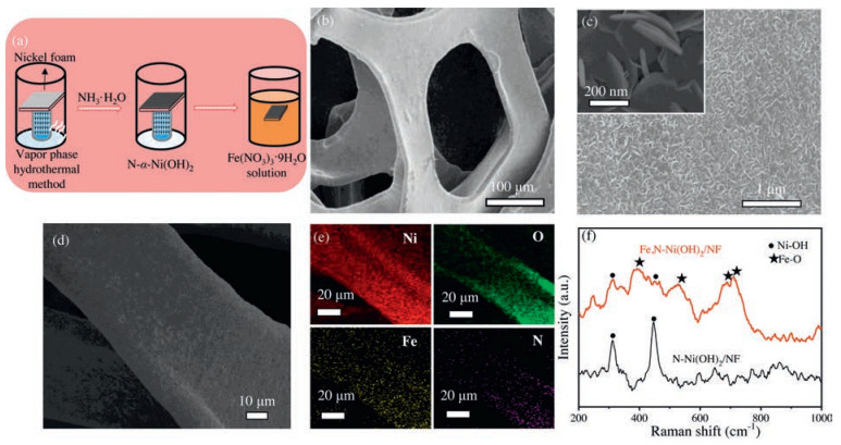
The fabrication process of the 3D Fe, N-Ni(OH)2/NF was based on two steps (Fig. 1a): Firstly, a piece of acid-prepared Ni foam was soaked into ammonia solution and heated at 90 ℃ for 8h. Secondly, the dry N-Ni(OH)2 on Ni foam was dipped in Fe(NO3)3 solution and dried spontaneously in fume hood. Besides, the synthetic details were provided in Supporting information. We methodically figured out the effects of Fe contents to obtain the highest OER capacity, and the Fe(NO3)3 solution concentration of 0.1mol/L was optimized (Fig. S1 in Supporting information). The field emission scanning electron microscope (FESEM) and transmission electron microscope (TEM) images presented that the Fe, N-Ni(OH)2 nanosheets were homogeneously grown on Ni foam (Figs. 1b and c and Fig. S2 in Supporting information). The elemental mapping images resulted via energy-dispersive X-ray spectroscopy (EDX) exhibited that the actual presence of Fe, Ni, N, and O elements in 3D Fe, N-Ni(OH)2/NF (Figs. 1d and e). The X-ray diffraction (XRD) pattern of 3D Fe, N-Ni(OH)2/NF showed five featured XRD peaks centered at 19.2°, 33.1°, 38.5°, 59.0°, and 62.7° which could be attributed to the (001), (100), (101), (110) and (111) of α-Ni(OH)2 planes, confirming the existence of α-Ni(OH)2 (Fig. S3 in Supporting information), without any peaks for Fe. The high resolution transmission electron microscope (HRTEM) of N-Ni(OH)2/NF showed the interplanars of 0.270nm, 0.231nm, and 0.461nm, which could be attributed to the (001), (100), and (101) crystal planes of α-Ni(OH)2. Also, selected area electron diffraction (SAED) pattern showed the lattice planes of (001), (100), and (110) of crystalline α-Ni(OH)2 (Fig. S4 in Supporting information). Furthermore, Raman spectra of 3D Fe, N-Ni(OH)2/NF showed four peaks (392 cm-1, 531 cm-1, 679 cm-1, and 707 cm-1) which were related to Fe-O bond. Besides, the other two peaks (308 cm-1 and 451 cm-1) were assigned to the Ni-O bond peaks (Fig. 1f) [47, 48]. The results above showed the Fe was introduced and Fe, N-Ni(OH)2 nanosheets were successfully grown in NF.

|
Download:
|
| Fig. 1. (a) The fabrication process and (b-d) field emission scanning electron microscope (FESEM) images of Fe, N-Ni(OH)2/NF, inset: the enlarged FESEM image. (e) Elemental mappings of 3D Fe, N-Ni(OH)2/NF. (f) The Raman spectra of Fe, N-Ni(OH)2/NF and N-Ni(OH)2/NF. | |
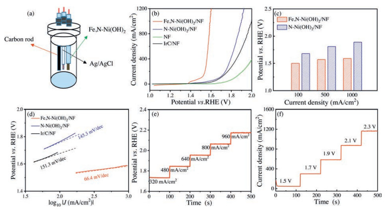
The OER performance of 3D Fe, N-Ni(OH)2/NF was studied through using a three-electrode system, while N-Ni(OH)2/NF, pure NF and commercial Ir/C/NF were used as references (Fig. 2a). As shown in Fig. 2b, the 3D Fe, N-Ni(OH)2/NF required a lowest OER potential of 1.50V at 100mA/cm2, which was smaller than that of N-Ni(OH)2/NF, NF and Ir/C/NF (1.68V, 1.83V, and 1.69V, respectively). The potential reported here was switched to the value versus the reversible hydrogen electrode (RHE). The 3D Fe, N-Ni(OH)2/NF only required low potentials of 1.5V, 1.57V, and 1.59V to realize the ultra-high current densities of 100mA/cm2, 500mA/cm2, and 1000mA/cm2, respectively (Fig. 2c). Notably, a high current density of 1300mA/cm2 (> 1000mA/cm2) can be achieved at a relative low potential of 1.61V, which made the 3D Fe, N-Ni(OH)2/NF a promising OER electrocatalyst towards practical application in industrial water splitting in basic electrolyte [37, 38]. The 3D Fe, N-Ni(OH)2/NF showed a much higher OER catalytic activity than the N-Ni(OH)2/NF with potentials of 1.68V, 1.81V and 1.89V at 100mA/cm2, 500mA/cm2, and 1000mA/cm2, respectively. The Tafel plots showed a lower Tafel slope of 66.4mV/dec for 3D Fe, N-Ni(OH)2/NF as compared to that of 145.3mV/dec for N-Ni(OH)2/NF, indicating faster OER kinetics of Fe, N-Ni(OH)2/NF (Fig. 2d). The multiple-current step curve of the 3D Fe, N-Ni(OH)2/NF at increasing current densities from 320 to 960mA/cm2 is shown in Fig. 2e. With the start current density of 320mA/cm2, the potential step located at 1.72V remained uniform for the rest 200s, and the rest four steps also showed similar trends. Moreover, the multiple-potential-steps of 3D Fe, N-Ni(OH)2/NF showed the potential from 1.50 to 2.30V for three cycles with the start level of 47mA/cm2 at 1.50V (Fig. 2f) [49].

|
Download:
|
| Fig. 2. (a) The scheme of electrochemical cell. (b) Polarization curves of 3D Fe, N-Ni(OH)2/NF, N-Ni(OH)2/NF, NF and Ir/C/NF. (c) Comparison of potentials required at the current densities of 100 mA/cm2, 500 mA/cm2, and 1000 mA/cm2 for Fe, N-Ni(OH)2/NF and N-Ni(OH)2/NF electrocatalysts. (d) Tafel plots of Fe, N-Ni(OH)2/NF, N-Ni(OH)2/NF and Ir/C/NF. (e) Multiple-current step curve and (f) multiple-potential step curve of Fe, N-Ni(OH)2/NF without iR-corrected. All above data were tested in 1.0 mol/L KOH. | |
Double layer capacitances (Cdl) of Fe, N-Ni(OH)2/NF was 23.3mF/cm2, which was higher than that of N-Ni(OH)2/NF (21.5mF/cm2) (Fig. 3a), indicating larger active surface area of Fe, N-Ni(OH) 2/NF [50]. Besides, the charge transfer resistance of the electrodes for the OER evaluated by electrochemical impedance spectroscopy (EIS) are shown in Fig. 3b, and the 3D Fe, N-Ni(OH)2/NF exhibited a much smaller charge-transfer resistance compared with the N-Ni(OH)2/NF, NF and Ir/C/NF, indicating a fast electron transfer in the 3D Fe, N-Ni(OH)2/NF. Moreover, chronopotentiometric measurement of Fe, N-Ni(OH)2/NF (Fig. 3c) showed excellent potential sustentions with initial values of 2.1V and 1.9V at around 1000mA/cm2 and 500mA/cm2 respectively after a long period of 10 h test, verifying an intensive stability. What's more, Fig. 3d exhibited the potential at 100mA/cm2 and corresponding Tafel slope of Fe, N-Ni(OH)2/NF, which compared well with those previously reported Ni/Fe-based selenides and other nonprecious OER electrocatalysts in 1.0mol/L KOH (Table S1 in Supporting information).

|
Download:
|
| Fig. 3. (a) ECSAs of Fe, N-Ni(OH)2/NF and N-Ni(OH)2/NF. (b) Nyquist plots of Fe, N-Ni(OH)2/NF, N-Ni(OH)2/NF, NF, and Ir/C/NF. (c) Chronopotentiometric measurements of Fe, N-Ni(OH)2/NF at potentials of 1.9 V and 2.1 V without iR-correction. (d) Comparison of Tafel slopes and potentials required for a current density of 100 mA/cm2. | |
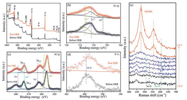
To further explore the structure change of Fe, N-Ni(OH)2 before and after OER, the X-ray photoelectron spectroscopy (XPS) measurements were conducted to probe the mechanism towards the OER performance (Fig. 4a). The intensity of Ni 2p had no obvious change while the binding energy of Fe 2p had positive shifts about 0.6eV which could be attributed to the oxidation of Fe ions (Figs. 4b and c) [3]. The intensity of N 1s also showed an ignored change, indicating that the presence of N was stable during the OER process owing to the introduction of Fe (Fig. 4d). Moreover, for the purpose of figuring out electrocatalytic mechanism of Fe, N-Ni(OH)2/NF during the OER process, in-situ electrochemical Raman spectroscopy was conducted at different applied potentials in 1.0mol/L KOH (Fig. 4e). The Ni-O peaks located at 307 cm-1 and 455 cm-1, as well as Fe-O peaks located at 528 cm-1 and 716 cm-1 were maintained at low potentials of 1.0V [48]. The intensity of Ni-OH decreased with applied potential increasing to 1.50V. Meanwhile, two peaks located at 473 cm-1 and 557 cm-1 for NiOOH increased with applied potential increasing above 1.60V [51, 52], and thenα-Ni(OH)2 persistently converted to NiOOH when the potential was above 1.80V. Hence, the amorphous NiOOH was verified comprehensively to be the active species leading to the improved OER performance based on above results. Furthermore, the induction of Fe into the Ni(OH)2 lattice may promote the phase transformation of Ni(OH)2 to NiOOH, which is beneficial to obtain high OER activity [10, 34-36].

|
Download:
|
| Fig. 4. (a) XPS survey spectra of Fe, N-Ni(OH)2/NF and N-Ni(OH)2/NF. High revolution (b) Fe 2p, (c) Ni 2p, and (d) N 1s of Fe, N-Ni(OH)2/NF before and post OER process. (e) In-suit Raman spectra of the 3D Fe, N-Ni(OH)2/NF with the potentials from 1.0 V to 1.8 V. | |
Meanwhile, more comparative experiments were carried out to explore the optimized conditions for Fe, N-Ni(OH)2 to present the best OER activity. Fig. S11 (Supporting information) showed the polarization curves of Fe, N-Ni-Ni(OH)2/NF with different hydrothermal times. When treated through ammonia hydrothermal method for 8h, Fe, N-Ni(OH)2/NF exhibited outstanding OER activity. Besides, the effect of hydrothermal temperature was investigated to confirm 90 ℃ as the optimized choice.
In conclusion, we have demonstrated a facile method to fabricate 3D N and Fe doped α-Ni(OH)2 nanosheets grown on Ni foam through the ammonia hydrothermal and impregnation methods to conduct OER under ultra-high current densities in alkaline electrolyte. The as-resultant Fe, N-Ni(OH)2/NF catalyst delivered low potentials of 1.57V and 1.59V to trigger the OER under ultra-high current densities of 500mA/cm2 and 1000mA/cm2 with strong durability, respectively, which compared well with the potentials of previously reported NiFe-based electrocatalysts toward the same current densities and were even superior to the benchmark Ir/C/NF electrode. In-situ Raman spectroscopy was employed to confirm NiOOH as the active species in Fe, N-Ni(OH)2/NF during OER process. The excellent OER electrocatalytic performances can be attributed to the optimized electronic structure through N doping. Furthermore, the incorporation of Fe into Ni(OH)2 lattice helped the phase transformation of Ni(OH)2 to NiOOH, and thus played a crucial role in efficient OER process. The as-prepared Fe, N-Ni(OH)2/NF presented in this work may offer new ideas to synthesize transition metal based hydroxides and provide new insights into the study of OER process towards ultra-high current densities.
Declaration of competing interestThe authors report no declarations of interest.
AcknowledgmentsS. Lyu thanks Key Laboratory of Biomass Chemical Engineering of Ministry of Education, College of Chemical and Biological Engineering for the use of their equipment. S. Lyu thank Prof. Yang Hou of Zhejiang University for using the experimental techniques of his research group.
Appendix A. Supplementary dataSupplementarymaterial related to this article can befound, in the online version, at doi: https://doi.org/10.1016/j.cclet.2020.09.030.
| [1] |
Y. Hou, M. Qiu, T. Zhang, et al., Adv. Mater. 29 (2017) 1604480. DOI:10.1002/adma.201604480 |
| [2] |
M. Asnavandi, Y.C. Yin, Y.B. Li, C.H. Sun, C. Zhao, ACS Energy Lett. 3 (2018) 1515-1520. DOI:10.1021/acsenergylett.8b00696 |
| [3] |
X.D. Cheng, Z.Y. Pan, C.J. Lei, et al., J. Mater. Chem. A 7 (2019) 965-971. DOI:10.1039/C8TA11223A |
| [4] |
X.D. Cheng, C.J. Lei, J. Yang, et al., Chem Electron Chem 5 (2018) 3866-3872. DOI:10.1002/celc.201801104 |
| [5] |
C.J. Lei, S.L. Lyu, J.C. Si, et al., Chem Cat Chem 11 (2019) 5855-5874. DOI:10.1002/cctc.201901707 |
| [6] |
N.T. Suen, S.F. Hung, Q. Quan, et al., Chem. Soc. Rev. 46 (2017) 337-365. DOI:10.1039/C6CS00328A |
| [7] |
Y. Lee, J. Suntivich, K.J. May, E.E. Perry, Y. Shao-Horn, J. Phys, Chem. Lett. 3 (2012) 399-404. DOI:10.1021/jz2016507 |
| [8] |
J.D. Blakemore, N.D. Schley, M.N. Kushner-Lenhoff, et al., Inorg. Chem. 51 (2012) 7749-7763. DOI:10.1021/ic300764f |
| [9] |
M.A. Younis, S.L. Lyu, Q.D. Zhao, et al., BMC Mat. 1 (2019) 6. DOI:10.1186/s42833-019-0006-2 |
| [10] |
K.Y. Zhu, X.F. Zhu, W.S. Yang, Angew. Chem. Int. Ed. 58 (2019) 1252-1265. DOI:10.1002/anie.201802923 |
| [11] |
C.J. Lei, Y. Wang, Y. Hou, et al., Energy Environ. Sci. 12 (2019) 149-156. DOI:10.1039/C8EE01841C |
| [12] |
C.J. Lei, H.Q. Chen, J.H. Cao, et al., Adv. Energy Mater. 8 (2018) 1801912. DOI:10.1002/aenm.201801912 |
| [13] |
L. Han, S.J. Dong, E. Wang, Adv. Mater. 28 (2016) 9266-9291. DOI:10.1002/adma.201602270 |
| [14] |
K.Y. Zhu, T. Wu, Y. Zhu, et al., ACS Energy Lett. 2 (2017) 1654-1660. DOI:10.1021/acsenergylett.7b00434 |
| [15] |
B.C. Weng, F.H. Xu, C.L. Wang, et al., Energy Environ. Sci. 10 (2017) 121-128. DOI:10.1039/C6EE03088B |
| [16] |
H.S. Fan, H. Yu, Y.F. Zhang, et al., Angew. Chem. Int. Ed. 56 (2017) 12566-12570. DOI:10.1002/anie.201706610 |
| [17] |
T.Y. Ma, J.L. Cao, M. Jaroniec, S.Z. Qiao, Angew. Chem. Int. Ed. 55 (2016) 1138-1142. DOI:10.1002/anie.201509758 |
| [18] |
F.M. Wang, T.A. Shifa, X.Y. Zhan, et al., Nanoscale 7 (2015) 19764-19788. DOI:10.1039/C5NR06718A |
| [19] |
J. Masa, I. Sinev, H. Mistry, et al., Adv. Energy Mater. 7 (2017) 1700381. DOI:10.1002/aenm.201700381 |
| [20] |
B. Wurster, D. Grumelli, D. Hötger, R. Gutzler, K. Kern, J. Am. Chem. Soc. 138 (2016) 3623-3626. DOI:10.1021/jacs.5b10484 |
| [21] |
J.J. Duan, S. Chen, C. Zhao, Nat. Commun. 8 (2017) 15341. DOI:10.1038/ncomms15341 |
| [22] |
C. Liu, J. Wang, J.J. Wan, et al., Angew. Chem. Int. Ed. 59 (2020) 3630-3637. DOI:10.1002/anie.201914587 |
| [23] |
J. Suntivich, K.J. May, H.A. Gasteiger, J.B. Goodenough, Y. Shao-Horn, Science 334 (2011) 1383-1385. DOI:10.1126/science.1212858 |
| [24] |
K. Zhu, T. Wu, M. Li, et al., J. Mater. Chem. A 5 (2017) 19836-19845. DOI:10.1039/C7TA05404A |
| [25] |
W.T. Hong, M. Risch, K.A. Stoerzinger, et al., Energy Environ. Sci. 8 (2015) 1404-0427. DOI:10.1039/C4EE03869J |
| [26] |
K. Zhu, H. Liu, X. Li, et al., Electrochim. Acta 241 (2017) 433-439. DOI:10.1016/j.electacta.2017.04.167 |
| [27] |
J.Y.C. Chen, J.T. Miller, J.B. Gerken, S.S. Stahl, Energy Environ, Sci. 7 (2014) 1382-1386. DOI:10.1039/c3ee43811b |
| [28] |
H.Y. Wang, S.F. Hung, H.Y. Chen, et al., J. Am. Chem. Soc. 138 (2016) 36-39. DOI:10.1021/jacs.5b10525 |
| [29] |
H. Osgood, S.V. Devaguptapu, H. Xu, J. Cho, G. Wu, Nano Today 11 (2016) 601-625. DOI:10.1016/j.nantod.2016.09.001 |
| [30] |
T.Y. Ma, S. Dai, M. Jaroniec, S.Z. Qiao, Angew. Chem. Int. Ed. 55 (2016) 1138-1142. DOI:10.1002/anie.201509758 |
| [31] |
X. Lu, W.L. Yim, B.H.R. Suryanto, C. Zhao, J. Am. Chem. Soc. 137 (2015) 2901-2907. DOI:10.1021/ja509879r |
| [32] |
H.L. Chen, Q.D. Zhao, L.G. Gao, J.W. Ran, Y. Hou, ACS Sustain. Chem. Eng. 7 (2019) 4247-4254. DOI:10.1021/acssuschemeng.8b05953 |
| [33] |
X.Y. Zhang, J. Li, Y. Yang, et al., Adv. Mater. 30 (2018) 1803551. DOI:10.1002/adma.201803551 |
| [34] |
S. Klaus, Y. Cai, M.W. Louie, L. Trotochaud, A.T. Bell, J. Phys. Chem. C 119 (2015) 7243-7254. DOI:10.1021/acs.jpcc.5b00105 |
| [35] |
B.J. Trześniewski, O. Diaz-Morales, D.A. Vermaas, et al., J. Am. Chem. Soc. 137 (2015) 15112-15121. DOI:10.1021/jacs.5b06814 |
| [36] |
L. Trotochaud, S.L. Young, J.K. Ranney, S.W. Boettcher, J. Am. Chem. Soc. 136 (2014) 6744-6753. DOI:10.1021/ja502379c |
| [37] |
F. Yu, H.Q. Zhou, Y.F. Huang, et al., Nat. Commun. 9 (2018) 2551. DOI:10.1038/s41467-018-04746-z |
| [38] |
Y.P. Liu, X. Liang, L. Gu, et al., Nat. Commun. 9 (2018) 2609. DOI:10.1038/s41467-018-05019-5 |
| [39] |
J.H. Hao, W.S. Yang, J.W. Hou, et al., J. Mater. Chem. A 5 (2017) 17811-17816. DOI:10.1039/C7TA03663A |
| [40] |
L.Y. Wen, R. Xu, Y. Mi, Y. Lei, Nat. Nanotechnol. 12 (2017) 244-250. DOI:10.1038/nnano.2016.257 |
| [41] |
J.K. Norskov, T. Bligaard, J. Rossmeisl, C.H. Christensen, Nat. Chem. 1 (2009) 37-46. DOI:10.1038/nchem.121 |
| [42] |
J.H. Hao, W.S. Yang, Z. Peng, et al., ACS Catal. 7 (2017) 4214-4220. DOI:10.1021/acscatal.7b00792 |
| [43] |
J.X. Gu, S. Magagula, J.X. Zhao, Z.F. Chen, Small Methods 3 (2019) 1800550. DOI:10.1002/smtd.201800550 |
| [44] |
Y.F. Zhan, X. Yu, L.M. Cao, et al., Int. J. Hydrogen Energy 41 (2016) 13493-13503. DOI:10.1016/j.ijhydene.2016.06.087 |
| [45] |
Z.C. Wang, W.J. Xu, X.K. Chen, et al., Adv. Funct. Mater. 29 (2019) 1902875. DOI:10.1002/adfm.201902875 |
| [46] |
X.X. Zou, X.X. Huang, A. Goswami, et al., Angew. Chem. 126 (2014) 4461-4465. DOI:10.1002/ange.201311111 |
| [47] |
I. Chourpa, L. Douziech-Eyrolles, L. Ngaboni-Okassa, et al., Analyst 130 (2005) 1395-1403. DOI:10.1039/b419004a |
| [48] |
S. Haschke, D. Pankin, Y. Petrov, et al., ChemSusChem 10 (2017) 3644-3651. DOI:10.1002/cssc.201701068 |
| [49] |
J.H. Cao, C.J. Lei, B. Yang, Batt. Supercaps 2 (2019) 348-354. DOI:10.1002/batt.201800098 |
| [50] |
Y.M. Liu, Y. Su, X. Quan, et al., ACS Catal. 8 (2018) 1186-1191. DOI:10.1021/acscatal.7b02165 |
| [51] |
X. Zou, Y.P. Liu, G.D. Li, et al., Adv. Mater. 29 (2017) 1700404. DOI:10.1002/adma.201700404 |
| [52] |
M.W. Louie, A.T. Bell, J. Am. Chem. Soc. 135 (2013) 12329-12337. DOI:10.1021/ja405351s |