 2021, Vol. 32


b College of Chemistry and Material Science, Hebei Normal University, Shijiazhuang 050024, China;
c Petroleum Geology Research and Laboratory Center, Research Institute of Petroleum Exploration & Development (RIPED), PetroChina, Beijing 100083, China
Photoelectrochemical (PEC) water splitting is a promising technology to provide hydrogen fuel, which integrates solar energy conversion and water electrolysis into a single photoelectrode [1-3]. Particularly, photoanode has a core effect on the PEC water splitting system owing to the multiple electron transfer process in water oxidation [4-6]. The PEC water splitting on photoanodes involves the following process: the generation of electron–hole pairs after photo excitation; the charge separation and holes migration to the photoanode surface; and the water oxidation reaction in the photoanode/electrolyte interface [7-10]. Because of low price and high stability, TiO2 etc. metal oxide semiconductors have attracted considerable attention to make the continuous breakthroughs in solar to hydrogen conversion efficiency [11, 12]. For TiO2 photoanode, weak light absorption under solar light and slow surface water oxidation kinetics usually result in unsatisfied photoconversion efficiency.
It have been reported that the integration of water oxidation catalysts with photocatalyst can improve the reaction dynamics by reducing the overpotential of water oxidation and improving charge separation ability of semiconductor [13, 14]. Layered double hydroxides (LDHs) show extraordinary oxygen evolution reaction (OER) performances with low overpotential and high stability, therefore also attracted intensive attention as water oxidation cocatalysts in PEC water splitting [15-20]. We discovered that the modification of ZnFe-LDH or NiFe-LDH on TiO2 can efficiently improve the charge separation efficiency and surface OER kinetic process [19, 20]. The interface structure and the matched band position in these TiO2/LDHs photoanodes play a key role in the final photoanodes activity. In spite of all this progress, the PEC solar-to-fuel conversion efficiency still cannot satisfy the requirement in practice due to the ultralow utilization of light, which makes it highly necessary to further exploration of TiO2 photoanodes with visible light absorption. Phthalocyanine copper (CuPc) is one of organic semiconductors with high charge-transport properties, excellent thermal and chemical stability, which inspires great interest in PEC photoelectrode synthesis [21-23]. When combined with TiO2, CuPc may act as an efficient photosensitizer which derives in high photo-absorption and thereby gives high PEC performance.
Taking advantage of electronegative phthalocyanine ligands and positive LDH nanosheets, we successfully demonstrate the construction of a ternary TiO2/CuPc/NiFe-LDH photoanode, which involves the assembling of CuPc molecules and NiFe-LDH nanosheets on TiO2 by a facile layer-by-layer (LBL) method. It is shown that the CuPc and NiFe-LDH were uniformly anchored onto TiO2 nanorods, and the loading mass can be fine controlled by the cycle numbers. The optimal TiO2/CuPc/NiFe-LDH photoanode shows a photocurrent density of 2.10 mA/cm2 at 0.6 V vs. SCE, which is 5.7 times higher than that of pristine TiO2. An integrated studies reveal that CuPc loading on TiO2 bring strong visible light absorption; NiFe-LDH as a cocatalyst accelerates the surface water oxidation reaction.
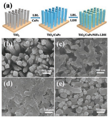
As shown in Fig. 1a, the synthesis of TiO2/CuPc/NiFe-LDH photoanode involves the TiO2 alternately immersed in copper(Ⅱ) phthalocyanine (CuPc) and exfoliated NiFe-LDH nanosheets solution through LBL method (see details in the experimental sections in Supporting information). The TiO2 nanorods were vertically grown on FTO substrate by hydrothermal method, with rather rough surface and diameter of 100–150 nm, length of 2.5 μm (Fig. 1b and Fig. S1 in Supporting information). The TiO2 nanorods became much smooth after CuPc (negatively-charged ligand) absorbed on the TiO2 surface (denoted as TiO2/CuPc, Fig. 1c). Then positively-charged NiFe-LDH nanosheets were further adhered on TiO2/CuPc by electrostatic interaction. Finally, TiO2 nanorods were cross links with CuPc and NiFe-LDH after 6 times cycle in CuPc and NiFe-LDH solution (Fig. 1d). The cross-section SEM images show that the introduced CuPc and NiFe-LDH are distributed uniformly on these TiO2 samples (Fig. S2 in Supporting information). In addition, TiO2/NiFe-LDH sample was fabricated to give a comparison study (Fig. 1e).

|
Download:
|
| Fig. 1. (a) Schematic illustration for the fabrication of TiO2/CuPc/NiFe-LDH. SEM images of (b) TiO2, (c) TiO2/CuPc, (d) TiO2/CuPc/NiFe-LDH and (e) TiO2/NiFe-LDH, respectively. | |
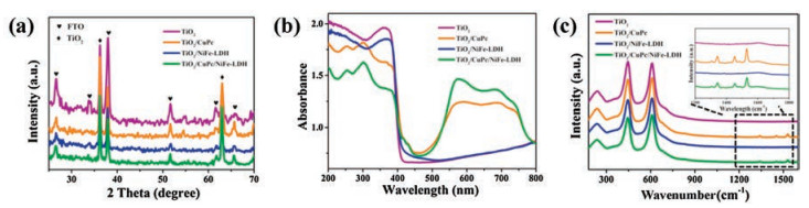
The composition and phase structure of obtained TiO2, TiO2/CuPc, TiO2/NiFe-LDH and TiO2/CuPc/NiFe-LDH were investigated by X-ray diffraction (XRD), UV–vis diffuse reflection and Raman spectra. XRD patterns of four prepared samples (Fig. 2a) show two sharp reflections at 2θ = 36.1° and 62.8°, corresponding to the (101) and (002) diffraction peaks of rutile TiO2, respectively [24]. But the signals of CuPc and NiFe-LDH are missed in TiO2/CuPc/NiFe-LDH, which can be attributed to the low concentration of CuPc and NiFe-LDH. In the UV–vis diffuse reflection spectroscopy (Fig. 2b), pristine TiO2 sample shows strong absorption in the UV light region. Slightly enhanced absorption at 400–500 nm was observed in TiO2/NiFe-LDH, originating from NiFe-LDH [25]. The visible light absorption of exfoliated NiFe-LDH was confirmed by the UV–vis absorption spectrum (Fig. S3 in Supporting information). In case of TiO2/CuPc and TiO2/CuPc/NiFe-LDH, the absorbance in the visible light region was significantly enhanced. CuPc has absorption edge at ~530 nm and the calculated bandgap through the Tauc analyses is 2.35 eV (Fig. S4 in Supporting information). The Raman spectra of the four samples show three peaks at 240 cm-1, 445 cm-1 and 608 cm-1, which can be attributed to the second order effect of vibration mode in rutile TiO2 [26]. The signals of CuPc at 1340 cm-1, 1450 cm-1 and 1530 cm-1 can be observed in TiO2/CuPc and TiO2/CuPc/NiFe-LDH [27]. Fe 2p and Ni 2p XPS spectra of TiO2/CuPc/NiFe-LDH were further investigated, confirming the successfully loading of NiFe-LDH in the composite photoanode (Fig. S5 in Supporting information). Compare with exfoliated NiFe-LDH, no shift of the Fe 2p and Ni 2p peaks in TiO2/CuPc/NiFe-LDH were observed, suggesting weak interaction between NiFe-LDH and CuPc. The above results demonstrated the successful loading of CuPc and NiFe-LDH in TiO2/CuPc/NiFe-LDH by the LBL method.

|
Download:
|
| Fig. 2. (a) XRD patterns, (b) UV–vis diffuse reflectance spectra and (c) Raman spectra of TiO2, TiO2/CuPc, TiO2/NiFe-LDH and TiO2/CuPc/NiFe-LDH, respectively. | |
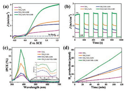
The PEC measurements were carried out using TiO2, TiO2/CuPc, TiO2/NiFe-LDH and TiO2/CuPc/NiFe-LDH samples as photoanodes in 0.5 mol/L Na2SO4 aqueous solution. In dark condition, electrochemical water splitting cannot react for these four samples at bias < 1.2 V vs. SCE (Fig. 3a). Under illumination, pristine TiO2 displays a relatively low photocurrent density of 0.37 mA/cm2 at 0.6 V vs. SCE. In contrast, the TiO2/NiFe-LDH and TiO2/CuPc photoanodes exhibit an enhanced photocurrent density of 0.97 mA/cm2 and 1.06 mA/cm2, respectively. The photocurrent density of TiO2/CuPc/NiFe-LDH further increased to 2.10 mA/cm2 at 0.6 V vs. SCE. It can be found that the fabricated TiO2/CuPc/NiFe-LDH has superior photocurrent density than most reported TiO2-based works (Table S1 in Supporting information). Amperometric I–t curves of four samples were measured under chopped light illumination (Fig. 3b). It can be observed that these photoanodes exhibited rapid and reproducible photocurrent response, corresponding to the ON-OFF signals of the light. Moreover, it is found that the TiO2 and TiO2/CuPc/NiFe-LDH show excellent photocurrent stability while the photocurrent of TiO2/CuPc and TiO2/NiFe-LDH has a decrease. The PEC measurements under visible light were further measured (Fig. S6 in Supporting information). Comparing with TiO2/NiFe-LDH (21.4 μA/cm2 at 0.6 V vs. SCE) or TiO2/CuPc (25.9 μA/cm2 at 0.6 V vs. SCE), the ternary photoanode TiO2/CuPc/NiFe-LDH showed more significant improvement with the photocurrent density of 52.3 μA/cm2 at same applied bias. Incident photon to current efficiency (IPCE) results of four samples was shown in Fig. 3c, displaying high photocatalytic activity in the UV light region. The maximum IPCEs are obtained at 375 nm, which are 7.94%, 12.48%, 11.59%, and 14.97% for TiO2, TiO2/CuPc, TiO2/NiFe-LDH, and TiO2/CuPc/NiFe-LDH samples, respectively. In the visible light region, the IPCE of TiO2/CuPc/NiFe-LDH is much higher than TiO2 (Fig. 3c inset), which is consistent with the PEC performance under visible light illumination. The IPCE of TiO 2/NiFe-LDH shows small improvement in the range of 450–650 nm, which can be attributed to the photocatalytic properties of NiFe-LDH. In order to confirm the water splitting products, the photocurrent and produced H2 were both monitored during the photoelectrolysis measurements. By comparing the theoretical and actual H2 yield, the average Faraday efficiency was calculated to be 99%, 97%, 98% and 99% for TiO2, TiO2/CuPc, TiO2/NiFe-LDH and TiO2/CuPc/NiFe-LDH samples, respectively (Fig. 3d and Table S2 in Supporting information). The durability test shows that TiO2/CuPc/NiFe-LDH samples give a relatively stable photocurrent density under illumination for 5 h (< 5% current decay, Fig. S7 in Supporting information). However, the photocurrent density of the TiO2/NiFe-LDH and TiO2/CuPc has a significant decrease along with the time. The results above demonstrate that introduction of CuPc or NiFe-LDH can improve the PEC performance of TiO2 photoanode and the obtained ternary TiO2/CuPc/NiFe-LDH photoanode shows more superior stability and sunlight utilization efficiency.

|
Download:
|
| Fig. 3. (a) Current-voltage curves, (b) amperometric I-t curves at potential of 1.23 V vs. RHE under chopped light illumination, (c) IPCEs measured at 1.23 V vs. RHE and (d) total H2 production of TiO2, TiO2/CuPc, TiO2/NiFe-LDH and TiO2/CuPc/NiFe-LDH, respectively. | |
The PEC performance of TiO2/CuPc/NiFe-LDH with different loading mass of CuPc and NiFe-LDH was also investigated. The loading mass onto TiO2 can be tuned by the cycle numbers of CuPc and NiFe-LDH in LBL process (denoted as TiO2/CuPc/NiFe-LDH-n, where n is the bilayer numbers). The LBL process of TiO2/CuPc/NiFe-LDH-n was monitored by UV–vis spectra (Fig. 4a), where visible light absorption intensities at 600 cm-1 increased from 0.78 to 1.37 along with the bilayer numbers increase from 2 to 8. In addition, Raman spectra at ~1340 cm-1, 1450 cm-1 and 1530 cm-1 also has a gradually enhancement as the bilayer numbers increase (Fig. 4b). SEM images show that the surface of TiO2 is completely covered by CuPc and NiFe-LDH as the bilayer numbers increase to 6 (Fig. S8 in Supporting information). The peaks of CuPc or NiFe-LDH cannot be observed in the XRD of TiO2/CuPc/NiFe-LDH-8, suggesting that the loading mass of CuPc and NiFe-LDH was relative low (Fig. S9 in Supporting information). The PEC measurements for TiO2/CuPc/NiFe-LDH-n photoanodes are shown in Fig. 4c. The photocurrent density gradually increases from 0.75 mA/cm2 (n = 2) to 2.10 mA/cm2 (n = 6) at 0.6 V vs. SCE, but decreases to 1.44 mA/cm2 in TiO2/CuPc/NiFe-LDH-8. Therefore, 6 bilayers numbers is more suitable in the series of TiO2/CuPc/NiFe-LDH samples. Moreover, the photocurrent density of TiO2/CuPc/NiFe-LDH-6 showed the largest photocurrent density under visible light in these samples (Fig. S10 in Supporting information). In addition, it is worth mention that all the TiO2/CuPc/NiFe-LDH samples in other parts were discussed with TiO2/CuPc/NiFe-LDH-6.

|
Download:
|
| Fig. 4. (a) UV–vis diffuse reflectance spectra, (b) Raman spectra and (c) current-voltage curves of TiO2, TiO2/CuPc/NiFe-LDH-2, TiO2/CuPc/NiFe-LDH-4, TiO2/CuPc/NiFe-LDH-6, TiO2/CuPc/NiFe-LDH-8, respectively. | |
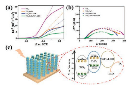
To give deep insights into the effect of CuPc and NiFe-LDH in TiO2/CuPc/NiFe-LDH, Mott-Schottky measurements was used to investigate the semiconducting properties of obtained four photoanodes [28]. The Mott-Schottky plots of four samples show positive slope, suggesting an n-type TiO2 semiconductor properties (Fig. 5a). The charge carrier density was assessed according to the Mott-Schottky equation, which were 6.62×10¹⁶, 1.13×10¹⁷, 1.59×10¹⁷ and 6.92×1017 cm-3 for TiO2, TiO2/CuPc, TiO2/NiFe-LDH and TiO2/CuPc/NiFe-LDH, respectively (see details in the experimental sections in Supporting information). This demonstrates that CuPc or LDH can increase the carrier density of TiO2 surface, and the enhancement is more significant in TiO2/CuPc/NiFe-LDH sample. By extrapolating the Mott–Schottky plot, the intercept of TiO2/CuPc/NiFe-LDH sample is shift from −0.60 V to −0.48 V compared with that of TiO2. The positive shift suggests a decrease of the upward bending in band edge, which facilitates the charge transfer in the semiconductor/electrolyte interface [29]. The electrochemical impedance spectroscopy (EIS) studies for these four samples were carried out (Fig. 5b). After incorporation of CuPc or NiFe-LDH, the arc diameters decreased slightly in TiO2/CuPc and TiO2/NiFe-LDH, representing the smaller charge transfer resistance [30]. The minimal arc radius in TiO2/CuPc/NiFe-LDH indicates the synergetic effect of CuPc and NiFe-LDH. The photoluminescence (PL) behaviors were measured (Fig. S11 in Supporting information), reflecting the recombination of electron and hole in the surface of semiconductors [31]. The PL emission spectra of TiO2 photoanode display strong PL emission peaks at 409 and 454 nm. By introducing of CuPc or NiFe-LDH, decreased PL emission intensity can be observed in TiO2/CuPc and TiO2/NiFe-LDH. Finally the lowest PL emission intensity in TiO2/CuPc/NiFe-LDH suggests a suppressed radiative recombination of generated charge carriers. In addition, the surface charge injection efficiency was calculated by photocurrent measured in the electrolyte with or without H2O2 (see details in the experimental sections in Supporting information). The charge injection efficiency of TiO2/CuPc at 0.6 V vs. SCE is 60.0%, which is comparable with that of TiO2 (58.0%). A giant improvement is obtained in TiO2/NiFe-LDH (79.2%) and TiO2/CuPc/NiFe-LDH 82.1%), suggesting the highly OER catalytic activity of NiFe-LDH in the photoanodes (Fig. S12 in Supporting information).

|
Download:
|
| Fig. 5. (a) Mott-Schottky plots collected at a frequency of 1 kHz in dark, (b) EIS measured at 0 V vs. SCE under illumination for the sample of TiO2, TiO2/CuPc, TiO2/NiFe-LDH and TiO2/CuPc/NiFe-LDH, respectively. (c) Schematic illustration of the PEC water oxidation process in the TiO2/CuPc/NiFe-LDH photoanode. | |
Given the above discussions, a mechanism for the enhanced PEC water splitting performance in this TiO2/CuPc/NiFe-LDH photoanode is proposed and shown in Fig. 5c. The photoexcited electron–hole pairs of TiO2 are generated under UV light illumination while CuPc can be excited under the visible light. The difference in band position for TiO2 and CuPc induce photo-generated electrons and holes transfer oppositely: electrons from CuPc to TiO2, while holes from TiO2 to CuPc and finally capture by NiFe-LDH [32, 33]. CuPc can broaden the spectral response and NiFe-LDH acts as the active site for water oxidation. The rapid transmissions and utilization of charge carriers suppress the recombination of electrons and holes generated by TiO2 and CuPc. The enhanced charge separation and injection efficiency was confirmed by the EIS and electrochemical testing. Consequently, by the synergetic effect of photosensitizer CuPc and cocatalyst NiFe-LDH, effective PEC water oxidation is performed in the TiO2/CuPc/NiFe-LDH photoanode with improved light absorption and charge utilization efficiency.
In summary, a ternary TiO2/CuPc/NiFe-LDH photoanode has been successfully prepared by a stepwise modificaiton of CuPc and exfoliated NiFe-LDH nanosheets onto TiO2 by LBL method. Due to the synergetic effect of photosensitizer and cocatalyst, the well-aligned TiO2/CuPc/NiFe-LDH significantly improves the light absorption ability and charge utilization efficiency. A deeper understanding based on the spectroscopy and electrochemical studies imply that the CuPc and NiFe-LDH can serve as photosensitizer and cocatalyst respectively, thereby improving the PEC water oxidation efficiency.
Declaration of competing interestThe authors declare that they have no known competing financial interests or personal relationships that could have appeared to influence the work reported in this paper.
AcknowledgmentsThis work was supported by the Beijing Natural Science Foundation (No. 2192040), the National Natural Science Foundation of China (Nos. 21922501, 21871021, 21521005 and 21902042) and the Science Foundation of Hebei Normal University (No. L2019B14).
Appendix A. Supplementary dataSupplementary material related to this article can be found, in the online version, at doi:https://doi.org/10.1016/j.cclet.2020.09.037.
| [1] |
R. Gao, D. Yan, Adv. Energy Mater. 11 (2019) 1900954. |
| [2] |
J.H. Kim, J.S. Lee, Adv. Mater. 20 (2019) 1806938. |
| [3] |
Z. Wei, B. Ding, H. Dou, et al., Chin. Chem. Lett. 30 (2020) 2110-2122. |
| [4] |
J. Xiao, L. Fan, F. Zhao, et al., J. Catal. 381 (2020) 139-149. DOI:10.1016/j.jcat.2019.10.033 |
| [5] |
G. Liu, Y. Zhao, R. Yao, et al., Chem. Eng. J. 355 (2019) 49-57. DOI:10.1016/j.cej.2018.08.100 |
| [6] |
L. Cai, Y. Du, X. Guan, Chin. Chem. Lett. 30 (2019) 2363-2367. DOI:10.1016/j.cclet.2019.07.020 |
| [7] |
G. Žerjav, M.S. Arshad, P. Djinović, et al., Nanoscale 13 (2017) 4578-4592. |
| [8] |
Y. Chen, J. Li, P. Liao, et al., Chin. Chem. Lett. 31 (2020) 1516-1519. DOI:10.1016/j.cclet.2019.12.013 |
| [9] |
R. Chen, S. Pang, H. An, et al., Nat. Energy 8 (2018) 655-663. |
| [10] |
Y. Si, S. Cao, Z. Wu, et al., Nano Energy 41 (2017) 488-493. DOI:10.1016/j.nanoen.2017.10.008 |
| [11] |
W. Li, A. Elzatahry, D. Aldhayan, et al., Chem. Soc. Rev. 22 (2018) 8203-8237. |
| [12] |
S. Feizpoor, A. Habibi-Yangjeh, Electrochim. Acta 262 (2018) 82-96. DOI:10.1016/j.electacta.2018.01.001 |
| [13] |
Y. Zhang, J. Huang, Y. Ding, Appl. Catal. B Environ. 198 (2016) 447-456. DOI:10.1016/j.apcatb.2016.05.078 |
| [14] |
S. Cao, C.J. Wang, W.F. Fu, et al., ChemSusChem 22 (2017) 4306-4323. |
| [15] |
W. Chen, T. Wang, J. Xue, et al., Small 10 (2017) 1602420. |
| [16] |
T. Li, X. Hao, S. Bai, et al., Acta Phys. Sin. 36 (2020) 1912005. |
| [17] |
H. She, P. Yue, X. Ma, et al., Appl. Catal. B Environ. 263 (2020) 118280. DOI:10.1016/j.apcatb.2019.118280 |
| [18] |
T.S. Munonde, H. Zheng, P.N. Nomngongo, Ultrason. Sonochem. 59 (2019) 104716. DOI:10.1016/j.ultsonch.2019.104716 |
| [19] |
F. Ning, M. Shao, S. Xu, et al., Energy Environ. Sci. 8 (2016) 263-2643. |
| [20] |
R. Zhang, M. Shao, S. Xu, et al., Nano Energy 33 (2017) 21-28. DOI:10.1016/j.nanoen.2017.01.020 |
| [21] |
X. Li, T. Zhang, Y. Chen, et al., Chem. Eng. J. 382 (2020) 122783. DOI:10.1016/j.cej.2019.122783 |
| [22] |
Y. Li, M. Yang, Z. Tian, et al., Front. Chem. 7 (2019) 334. DOI:10.3389/fchem.2019.00334 |
| [23] |
M. Ouyang, X. Hu, X. Shao, et al., RSC Adv. 59 (2019) 34382-34388. |
| [24] |
W. He, Y. Yang, L. Wang, et al., ChemSusChem 9 (2015) 1568-1576. DOI:10.1002/cssc.201403294 |
| [25] |
S. Bai, X. Yang, C. Liu, et al., ACS Sustainable Chem. Eng. 10 (2018) 12906-12913. |
| [26] |
M. Ye, D. Zheng, M. Wang, et al., ACS Appl. Mater. Interfaces 4 (2014) 2893-2901. DOI:10.1021/am405442n |
| [27] |
M. Ludemann, I.E. Brumboiu, O.D. Gordan, et al., J. Nanopart. Res. 11 (2011) 5855-5861. DOI:10.1007/s11051-011-0564-z |
| [28] |
Y. Wang, Y.-Y. Zhang, J. Tang, et al., ACS Nano 10 (2013) 9375-9383. |
| [29] |
W. Li, P. Da, Y. Zhang, et al., ACS Nano 11 (2014) 11770-11777. DOI:10.1021/nn5053684 |
| [30] |
X. Huai, L. Girardi, R. Lu, et al., Nano Energy 65 (2019) 104020. DOI:10.1016/j.nanoen.2019.104020 |
| [31] |
D. Dridi, Y. Litaiem, M. Karyaoui, et al., Eur. Phys. J. Appl. Phys. 2 (2019) 20401. |
| [32] |
J. Seo, N.J. Jeon, W.S. Yang, et al., Adv. Energy Mater. 20 (2015) 1501320. |
| [33] |
Q. Wang, T. Niu, L. Wang, et al., Chin. J. Catal. 4 (2018) 613-618. |