 2021, Vol. 32


b State Key Laboratory of Solidification Processing, Center for Nano Energy Materials, School of Materials Science and Engineering, Northwestern Polytechnical University and Shaanxi Joint Laboratory of Graphene (NPU), Xi'an 710072, China
Recently, PIBs have been widely researched as an extremely ascendant energy technology resulted from the moderate price and abundant potassium resources [1]. Whereas, the sluggish electrochemical reaction dynamics and electrode pulverization caused by the bigger radius of potassium-ion (r(K+) =1.38Å) have severely hindered its development [1-4]. Up to now, only a few materials including carbon-based [5-8], alloying/conversion-type [9-13] and organic composite [14] anodes have been reported for PIBs. Thus, the accelerated research of anode materials with small volume change and excellent cycle stability is urgent.
Metal sulfides, with the features of non-toxic, low cost, high theoretical capacity, are a kind of materials commonly used as the anode in lithium/sodium-ion batteries [15-18]. However, their stupendous volume variations and intrinsic insulation have resulted in structural disruptions and poor electrochemical performance. Especially, when using metal sulfides as anode for PIBs, the electrode deterioration caused by the tardiness of K+ migration will be amplified [19, 20]. Minimizing the size of metal sulfides could be a possible way towards these problems. Considering that the bitty diameter (< 10 nm) of quantum dots is beneficial to the electron/ion migration, it will be helpful to obtain excellent potassium ion storage performance [21, 22].
As a proof-of-concept, the uniform-dispersed ZnS quantum dots loading on reduced graphene oxide (ZnS QDs-rGO) composite was successfully prepared in this work [23-27]. ZnS quantum dots with the average diameter as small as 2.8 nm were in situ formed on rGO nanosheets. The design of minimized-dots loading on the conductive matrix can combine the advantages of quantum dots and graphene showing shorter potassium ions diffusion channels, smaller volume expansion, and higher electrode conductivity. On this basis, the electrochemical performance and reaction mechanism of ZnS QDs-rGO anode were studied. Eventually, the anode delivers an outstanding capacity of 122 mAh/g at 1.0 A/g over 500 cycles.
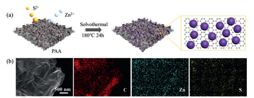
The ZnS QDs-rGO composite was prepared through a solvothermal method (Fig. 1a). In the ethylene glycol solvent, the surface of graphene oxide shows a negative charge state due to its rich oxygen-containing groups [28, 29]. During solvothermal processes, the graphene oxide adsorbs the positively charged zinc ions at first. Then, the zinc ions in situ react with sulfur ions to form anchored ZnS quantum dots. Meanwhile, the graphene oxide was reduced in the process [29, 30]. Although these oxygen-containing groups promote the uniform growth of quantum dots, the limited active sites may cause quantum dots to aggregate. To solve this problem, the surfactant PAA with rich carboxylic acid functional groups, was introduced to increase the nucleation site of ZnS [31]. The micro morphology and elemental mappings of the composite show that the functional PAA does promote the homogeneous distribution of ZnS quantum dots on the rGO sheets (Fig. 1b).

|
Download:
|
| Fig. 1. (a) Schematic illustration of the synthesis of the ZnS QDs-rGO. (b) SEM image and elemental mappings of ZnS QDs-rGO. | |
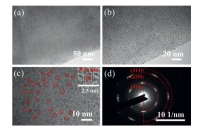
The morphology of ZnS QDs-rGO was characterized by transmission electron microscopy (TEM). Obviously, the ultra-small black spots separated from each other indicate that the active materials are dispersed homogeneously on the rGO nanosheets. No aggregated nanoclusters are observed (Fig. 2b). The statistical graph of particle size indicates that the size of quantum dots is concentrated around 2.8 nm (Fig. S1 in the Supporting information). Inset of high-resolution TEM (HRTEM) shows that the quantum dots have good crystallinity (Fig. 2c). The characteristic lattice plane (111) is distinctly performed, and its representative lattice spacing is 0.31 nm, which is well indexed to the ZnS [32]. Meanwhile, the selected area electron diffraction pattern (SAED) is a series of rings (Fig. 2d). These diffraction rings, from the innermost, are ascribed to (111), (220) and (311) planes of ZnS. Thus, ZnS QDs-rGO has been successfully prepared.

|
Download:
|
| Fig. 2. (a, b) TEM images, (c) HRTEM image and (d) SAED pattern of ZnS QDs-rGO. The inset of the Fig. 2c is the enlarged view of a single ZnS quantum dot. | |
To explore the morphology controllability of the ZnS QDs-rGO composite, comparative experiments have been conducted. A series of composites were synthesized by adjusting the proportion of PAA and other experimental parameters remained unchanged. The detailed preparation process is shown in the experimental section of Supporting information. The final products were characterized by scanning electron microscopy (SEM) and TEM (Figs. S2 and S3 in Supporting information). When the weight of PAA is halved, the ZnS nanoclusters (around 35−50 nm) composed of 3 nm primary particles are evenly distributed on the rGO sheets (ZnS NCs-rGO). When no PAA is added, the irregular ZnS agglomerates are formed (ZnS-rGO). These results fully prove the key role of PAA in increasing the active site of nucleation and inhibiting the growth of ZnS. On the basis of these results, a morphology-controllable preparation of ZnS quantum dots can be achieved.
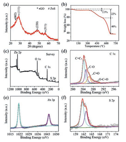
The phase composition and crystal structure of composite was characterized by X-ray diffraction (XRD), as shown in Fig. 3a. All main and sharp peaks are point to the face-centered cubic ZnS (JCPDS No. 65-1691) [32]. Another broad peak at 26.5° is indexed to the characteristic lattice plane (002) of rGO [29]. As a comparison, the XRD pattern of graphene oxide is displayed in Fig. S5 (Supporting information). The Fourier-transform infrared (FT-IR) spectra of composites are shown in Fig. S6 (Supporting information). These results further indicate that the GO has been reduced.

|
Download:
|
| Fig. 3. (a) XRD pattern and (b) TGA curve of ZnS QDs-rGO. (c) XPS survey spectrum of ZnS QDs-rGO and the high-resolution spectra of (d) C 1s, (e) Zn 2p and (f) S 2p. | |
The content percentage of ZnS in composite was quantified by thermo-gravimetric analysis (TGA), as shown in Fig. 3b. According to the transformation process of ZnS in the air, the weight loss below 150 ℃ could be related to the evaporation of water while the loss from 250 ℃ to 560 ℃ is interrelated to the oxidation of ZnS (ZnS + 3/2O2 = ZnO+SO2) and C (C+O2 = CO2) [32, 33]. We can infer that the ZnS QDs-rGO consists of 45.22wt% ZnS and the ZnS NCs-rGO contains 48.79wt% ZnS (Fig. S7 in Supporting information). The loading amount of ZnS in composite can be further increased to 51.17wt%, as shown in Figs. S8 and S9 (Supporting information).
The chemical composition and elemental status of the ZnS QDs-rGO were determined by X-ray photoelectron spectroscopy (XPS) analysis. The XPS survey spectrum demonstrates the chemical composition of C, Zn, and S in the composite (Fig. 3c). Four peaks in C 1s spectrum (Fig. 3d) can be indexed to C=C (284.2 eV), C-O (285.1 eV), C=O (286.3 eV) and O-C=O (288.1 eV). Two Zn 2p peaks (Fig. 3e) at 1044.8 eV and 1021.7 eV can be associated with the typical peaks of Zn 2p1/2 and Zn 2p3/2 orbit peaks in ZnS QDs-rGO. The S 2p spectrum (Fig. 3f) shows two peaks at 162.9 eV (S 2p1/2) and 161.7 eV (S 2p3/2) which further validates the presence of ZnS [34].
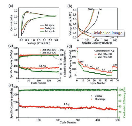
To evaluate the electrochemical performance, cyclic voltammetry (CV) curves were tested with a scan rate of 0.05 mV/s (Fig. 4a). In the first cycle, a broad cathodic peak less than 1.0 V can be viewed, which can be attributed to the irreversible formed solid electrolyte interphase (SEI) film [4, 35]. In the next cathodic cycles, two clear slop changes can be seen at 0.75 V and 0.15 V, which is contributed to the conversion reaction of ZnS & K+ and the alloying reaction of Zn & K +, respectively [18]. For anodic cycles, correspondingly two anodic peaks at 1.0 V and 0.4 V can be seen. As a result, the reaction process between ZnS and K+ is inferred as the following equations: ZnS + 2K+ + 2e− → Zn+K2S (1); Zn+xK+ + xe− → KxZn (2). The subsequent CV curves are depicted in Fig. S10 (Supporting information). It can be observed that the redox pair at a 0.15 V is markedly deviation to a lower potential. This can be attributed to the volume change of ZnS during the potassium ions insertion [36-39].

|
Download:
|
| Fig. 4. Electrochemical performances of ZnS QDs-rGO and ZnS NCs-rGO anode in PIBs. (a) The CV curves of ZnS QDs-rGO. (b) Galvanostatic charge-discharge curves of ZnS QDs-rGO at 0.1 A/g. (c) Galvanostatic cycle performances at 0.1 A/g. (d) Rate performances at 0.05, 0.1, 0.2, 0.5, 1 and 2 A/g. (e) long-term cycle performance of ZnS QDs-rGO at 1 A/g. | |
Fig. 4b exhibits the galvanostatic charge-discharge profiles of the ZnS QDs-rGO anode in 1st, 20th, 100th and 200th cycles at 0.1A/g. With the voltage drops to 1.0 V, the slope of the curve suddenly decreases in the first discharge process. The incipient discharge capacity of ZnS QDs-rGO is 720 mAh/g and the initial coulombic efficiency is 63%. The low coulombic efficiency should be attributed to the establishing process of irreversible SEI film [35]. The obvious two slope transitions at 0.4 V and 1.0 V during the charging process and two clear slope transitions at 0.75 V and 0.15 V in the discharge curves can be founded. After 200 cycles, the discharge capacity maintains 350.4 mAh/g and the coulombic efficiency keeps at 99.8%. As a comparison, the charge-discharge curves of ZnS NCs-rGO electrode were characterized (Fig. S11 in Supporting information). The coulombic efficiency is only 53.0% in the first cycle. In addition, the voltage platform is not conspicuous, indicating that the sluggish electrochemical reaction kinetics of ZnS NCs-rGO due to the agglomeration of ZnS quantum dots.
In order to prove the key effect of uniformly dispersed quantum dots with the smallest volume change on improved performance of PIBs. The galvanostatic cycle performances of these anodes were tested at 0.1A/g. The pure rGO anode as the benchmark was also tested (Fig. S12 in Supporting information). The capacity of ZnS QDs-rGO anode maintains 350.4 mAh/g and the coulombic efficiency reaches to 99.8% (Fig. 4c). On the contrary, the capacity of the ZnS NCs-rGO anode decreased significantly in the first 100 cycles and only 200 mAh/g can be obtained after 200 cycles (Fig. 4c). The capacity of ZnS-rGO anode continued to decline in all 200 cycles (Fig. S14 in Supporting information). The rate performances were also examined at different current densities from 0.05 A/g to 2.0 A/g (Fig. 4d). The ZnS QDs-rGO anode delivers excellent reversible capacities of 340.9, 265.6, 224.4, 168.8, 132.2 and 98.8 mAh/g at the constant current density of 0.05, 0.1, 0.2, 0.5, 1.0 and 2.0 A/g, respectively. The discharge capacity of 266 mAh/g can be restored when the current density is reduced to 0.05 A/g. Conversely, the rate performances of ZnS NCs-rGO and ZnS-rGO are worse (Fig. S15 in Supporting information). The capacity is nearly zero when the current density is 2.0 A/g. The comparative results confirm the structural advantages of ZnS QDs-rGO once again.
Furthermore, the long-term cycling stability of ZnS QDs-rGO anode was tested at 1.0 A/g (Fig. 4e). The discharge capacity maintains at 122 mAh/g even after 500 cycles. Compared with the electrochemical performances of other reported sulfide anodes in PIBs, as shown in Table S1 (Supporting information), ZnS QDs-rGO shows extremely high cycle stability. It is worth mentioning that the active material in this work has the smallest size compared to other nanoparticles in PIBs [38-41]. Several structural advantages of ZnS QDs-rGO have been summarized as follows: a) 2D materials as the template and buffer can alleviate the accumulation and volume expansion of quantum dots. b) The volume expansion effect can be infinitely weakened at the benefit of well-dispersed minimized quantum dots. c) The shortened potassium ions diffusion channels combined with highly conductive 2D materials can significantly improve the electrochemical performance of the composite.
In summary, uniform-dispersed ZnS QDs-rGO composite has been synthesized and investigated as an anode for PIBs. The ZnS QDs-rGO anode exhibits an unprecedented capacity of 122 mAh/g at 1.0 A/g over 500 cycles. Thus, ZnS QDs-rGO anode for PIBs has superior electrochemical performance, and the uniform-dispersed quantum dots-graphene structure has particular reference value for developing other electrode materials.
Declaration of competing interestThe authors declare that they have no known competing financial interests or personal relationships that could have appeared to influence the work reported in this paper.
AcknowledgmentsThe authors acknowledge the financial support of this work by the Science, Technology, and Innovation Commission of Shenzhen Municipality (Nos. JCYJ20180508151856806 and JCYJ20180306171121424), the Key R&D Program of Shanxi (No. 2019ZDLGY04-05), the National Natural Science Foundation of Shaanxi (Nos. 2019JLZ-01, 2019JLM-29 and 2020JQ-189), the National Natural Science Foundation of China (No. 21603175), the Research Fund of the State Key Laboratory of Solidification Processing (NPU), China (Nos. 2019-TS-06 and 2020-BJ-03), China Postdoctoral Science Foundation (No. 2018M641015).
Appendix A. Supplementary dataSupplementary material related to this article can be found, in the online version, at doi:https://doi.org/10.1016/j.cclet.2020.08.030.
| [1] |
J.C. Pramudita, D. Sehrawat, D. Goonetilleke, N. Sharma, Adv. Energy Mater. 7 (2017) 1602911. DOI:10.1002/aenm.201602911 |
| [2] |
N.N. Wang, C.X. Chu, X. Xu, et al., Adv. Energy Mater. 8 (2018) 1801888. DOI:10.1002/aenm.201801888 |
| [3] |
X.Y. Wu, D.P. Leonard, X.L. Ji, Chem. Mater. 29 (2017) 5031-5042. DOI:10.1021/acs.chemmater.7b01764 |
| [4] |
B. Huang, Z.F. Pan, X.Y. Su, L. An, J. Power Sources 395 (2018) 41-59. DOI:10.1016/j.jpowsour.2018.05.063 |
| [5] |
Z.X. Tai, Q. Zhang, Y.J. Liu, H.K. Liu, S.X. Dou, Carbon 123 (2017) 54-61. DOI:10.1016/j.carbon.2017.07.041 |
| [6] |
Y. Xu, C.L. Zhang, M. Zhou, et al., Nat. Commun. 9 (2018) 1720. DOI:10.1038/s41467-018-04190-z |
| [7] |
W. Wang, J.H. Zhou, Z.P. Wang, et al., Adv. Energy Mater. 8 (2018) 1701648. DOI:10.1002/aenm.201701648 |
| [8] |
G. Wang, X.H. Xiong, D. Xie, et al., J. Mater. Chem. A: Mater. Energy Sustain. 6 (2018) 24317-24323. DOI:10.1039/C8TA09751H |
| [9] |
W. Wang, B. Jiang, C. Qian, et al., Adv. Mater. 30 (2018) 1801812. DOI:10.1002/adma.201801812 |
| [10] |
Z. Huang, Z. Chen, S.S. Ding, C.M. Chen, M. Zhang, Mater. Lett. 219 (2018) 19-22. DOI:10.1016/j.matlet.2018.02.053 |
| [11] |
J. Bai, B.J. Xi, H.Z. Mao, et al., Adv. Mater. 30 (2018) 1802310. DOI:10.1002/adma.201802310 |
| [12] |
L. Yang, W.W. Hong, Y. Tian, et al., Chem. Eng. J. 385 (2020) 123838. DOI:10.1016/j.cej.2019.123838 |
| [13] |
T. Li, Q. Zhang, J. Energy Chem. 27 (2018) 373-374. DOI:10.1016/j.jechem.2017.12.009 |
| [14] |
Q. Xue, D.N. Li, Y.X. Huang, et al., J. Mater. Chem. A: Mater. Energy Sustain. 6 (2018) 12559-12564. DOI:10.1039/C8TA03921F |
| [15] |
L.F. Shen, Y. Wang, F.X. Wu, et al., Angew. Chem. Int. Ed. 58 (2019) 7238-7243. DOI:10.1002/anie.201901840 |
| [16] |
F.X. Wu, C.L. Zhao, S.Q. Chen, et al., Mater. Today 21 (2018) 960-973. DOI:10.1016/j.mattod.2018.03.004 |
| [17] |
Y. Huang, Y. Jiang, Z.F. Ma, et al., Nanomaterials 9 (2019) 469. DOI:10.3390/nano9030469 |
| [18] |
F.X. Wu, J. Maier, Y. Yu, Chem. Soc. Rev. 49 (2020) 1569-1614. DOI:10.1039/C7CS00863E |
| [19] |
T. Li, Q. Zhang, J. Energy Chem. 27 (2018) 373-374. DOI:10.1016/j.jechem.2017.12.009 |
| [20] |
V. Lakshmi, Y. Chen, A.A. Mikhaylov, et al., Chem. Commun. 53 (2017) 8272-8275. DOI:10.1039/C7CC03998K |
| [21] |
Z.X. Huang, B. Liu, D. Kong, Y. Wang, H.Y. Yang, Energy Storage Mater. 10 (2018) 92-101. DOI:10.1016/j.ensm.2017.08.008 |
| [22] |
H. Li, L. Jiang, Q. Feng, et al., Energy Storage Mater. 17 (2019) 157-166. DOI:10.1016/j.ensm.2018.07.021 |
| [23] |
C. Tang, H.F. Wang, J.Q. Huang, et al., Electro. Ener. Rev. 2 (2019) 332-371. DOI:10.1007/s41918-019-00033-7 |
| [24] |
R. Raccichini, A. Varzi, S. Passerini, B. Scrosati, Nat. Mater. 14 (2015) 271-279. DOI:10.1038/nmat4170 |
| [25] |
G. Li, B. Huang, Z. Pan, et al., Energy Environ. Sci. 12 (2019) 2030-2053. DOI:10.1039/C8EE03014F |
| [26] |
Z.X. Wei, B. Ding, H. Dou, et al., Chin. Chem. Lett. 30 (2019) 2110-2122. DOI:10.1016/j.cclet.2019.11.022 |
| [27] |
B.L. Xu, S.H. Qi, M.M. Jin, et al., Chin. Chem. Lett. 30 (2019) 2053-2064. DOI:10.1016/j.cclet.2019.10.028 |
| [28] |
S.N. Alam, N. Sharma, L. Kumar, Graphene 6 (2017) 1-18. DOI:10.4236/graphene.2017.61001 |
| [29] |
C. Nethravathi, M. Rajamathi, Carbon 46 (2008) 1994-1998. DOI:10.1016/j.carbon.2008.08.013 |
| [30] |
O.C. Compton, S.T. Nguyen, Small 6 (2010) 711-723. DOI:10.1002/smll.200901934 |
| [31] |
H.P. Soni, D. Parmar, N. Patel, M. Chawda, D. Bodas, Mater. Lett. 62 (2008) 2700-2703. DOI:10.1016/j.matlet.2008.01.019 |
| [32] |
W. Qin, D.S. Li, X.J. Zhang, et al., Electrochim. Acta 191 (2016) 435-443. DOI:10.1016/j.electacta.2016.01.116 |
| [33] |
M.L. Mao, L. Jiang, L.C. Wu, M. Zhang, T.H. Wang, J. Mater. Chem. A: Mater. Energy Sustain. 3 (2015) 13384-13389. DOI:10.1039/C5TA01501D |
| [34] |
J. Li, Y. Fu, X. Shi, Z. Xu, Z. Zhang, Chem. Eur. J. 23 (2017) 157-166. DOI:10.1002/chem.201604532 |
| [35] |
C.L. Yan, X. Gu, L. Zhang, et al., J. Mater. Chem. A: Mater. Energy Sustain. 6 (2018) 17371-17377. DOI:10.1039/C8TA05297B |
| [36] |
B. Jia, Y. Zhao, M. Qin, et al., J. Mater. Chem. A: Mater. Energy Sustain. 6 (2018) 11147-11153. DOI:10.1039/C8TA03166E |
| [37] |
X.D. Ren, Q. Zhao, W.D. Mcculloch, Y.Y. Wu, Nano Res. 10 (2017) 1313-1321. DOI:10.1007/s12274-016-1419-9 |
| [38] |
H. Gao, T.F. Zhou, Y. Zheng, et al., Adv. Funct. Mater. 27 (2017) 1702634. DOI:10.1002/adfm.201702634 |
| [39] |
Q.Y. Yu, J. Hu, Y.Z. Gao, et al., J. Alloys. Compd. 766 (2018) 1086-1091. DOI:10.1016/j.jallcom.2018.07.065 |
| [40] |
M.L. Mao, C.Y. Cui, M.G. Wu, et al., Nano Energy 45 (2018) 346-352. DOI:10.1016/j.nanoen.2018.01.001 |
| [41] |
D.G. Yin, Z. Chen, M. Zhang, J. Phys. Chem. Solids 126 (2019) 72-77. DOI:10.1016/j.jpcs.2018.10.029 |