 2021, Vol. 32


b School of Chemistry and Chemical Engineering, State Key Laboratory of Hollow-fiber Membrane Materials and Membrane Processes, Tiangong University, Tianjin 300387, China
 Ying Na received her B.S. degrees from Changchun University of Science and Technology in 2019. She is now an M.S. candidate in the School of Materials Science and Engineering at Tianjin University in China. Her research focuses on the design of electrode materials to improve the electrochemical performance for lithium-ion batteries;
 |
 Xiaohong Sun is an Associate Professor in School of Materials Science and Engineering at Tianjin University in China. She received her B.S. and pH.D. degree in 2005 and 2010 from Nankai University in China. Her research interests include the structure and morphology design, synthesis and characteristics of nanoscale and porous materials and their applications in electrochemical and energy storage;
 |
 Anran Fan received her B.S. degree from Jilin Jianzhu University of Science and Technology in 2017. She is currently undertaking her M.S. degree under the supervision of Pr. Xiaohong Sun in the School of Materials Science and Engineering, Tianjin University, China. Her research focuses on the design of electrode materials including the structure and morphology to improve the electrochemical performance for lithium-ion batteries and sodium-ion batteries;
 |
 Shu Cai is a Professor of the School of Materials Science and Engineering at Tianjin University, China. She received her pH.D. degree from Tianjin University in 2000. Her research focuses on synthesis of nanoparticles, and applications in sodium ion battery; processing and properties of oxide ceramics and composite ceramics; biomaterials for orthopedic application;
 |
 Chunming Zheng received the B.S., M.S. and pH.D. degree from Nankai University, China in 2002, 2006 and 2010. He is now a Professor of the School of Chemistry and Chemical Engineering at Tiangong University, China. His research interests include the controllable synthesis of nanoporous metal oxides and their applications in sustainable chemical and electrochemical processes.
 |
Lithium-ion batteries (LIBs) have become the main energy storage system for various civilian electronic equipment owing to their high specific energy, excellent charge retention ability and low toxicity [1, 2]. In addition, LIBs are gradually replacing traditional nickel-cadmium batteries and are used in deep-sea exploration, aerospace, military equipment and other fields [3]. Compared with civilian equipment, deep submersibles, planetary detectors, military mobile power supplies and other devices place stricter requirements on the performance of batteries, especially to provide electricity even at low temperatures. However, in the practical application of low temperatures (≤10 ℃), the energy and power of LIBs are reduced greatly [4]. It is reported that the energy and power density provided by commercial 18, 650 LIBs at -40 ℃ are only 5% and 1.25% of the values at room temperature, which severely limits its use in the cold-resistant fields such as the deep sea, aerospace and military [5, 6]. Hence, outstanding low-temperature performance is one of the urgent problems to be solved in the development of LIBs.
In recent years, many researchers have made in-depth studies on the main factors causing the poor performance of LIBs at low temperatures and summarized them into three aspects. (1) The viscosity of the electrolyte increases and the conductivity decreases significantly [7]. (2) The electrochemical impedance increases, especially the charge transfer resistance (Rct) [8]. (3) The diffusion capacity of Li+ reduces in the electrode material [9]. Above mentioned drawbacks jointly contribute to the severe polarization and inferior electrochemical activity of electrode materials at low temperatures, and thus resulting in sharp capacity fading of electrodes during charge-discharge processes. Furthermore, during low-temperature charging, especially at high rates, the anode is more prone to precipitate lithium metal and exacerbate the irreversible reaction with the electrolyte, which causes the cell polarization to increase again [10]. Eventually, the performance of the battery is further deteriorated. However, the types of electrolytes available are limited and the development of separators is relatively slow, so the current research on the low-temperature performance of LIBs mainly focuses on the modification of electrode materials. By enhancing the ion diffusion rate, electronic conductivity and spatial structure stability of electrode materials to improve its charge-discharge specific capacity at low temperatures.
In this review, we systematically analyze the major factors that limit the capacity of LIBs in combination with recent studies on low-temperature performance. Then, according to the different cathode and anode materials, the methods and the related action mechanisms for enhancing the capacity of LIBs in cold environments are summarized, including reducing the particle size, surface coating, designing structures and doping. Finally, the research direction of LIBs at low temperatures has prospected.
2. Methods for enhancing the low-temperature capacity of cathode materialsThe cathode is the core component of a LIB and directly affects its electrochemical performance. The capacity attenuation of the cathode material at low temperature is mainly caused by four factors: the reduced activation of the active material in the cathode leads to a decrease in capacity; the more difficult Li+ intercalation causes a certain discharge capacity loss; the increased electrochemical impedance reduces the electrochemical reaction kinetics, especially the Rct; the lattice contraction limits the diffusion of Li+ in the crystal and reduces the diffusion coefficient of Li+ [11, 12]. For these reasons, we focused on the improvement methods of LiFePO4, Li3V2(PO4)3, nickel-cobalt-manganese ternary materials, Li-rich materials and LiMn2O4 cathode materials that are often used at low temperatures (Table 1).
|
|
Table 1 Low-temperature capacity of different cathode materials. |
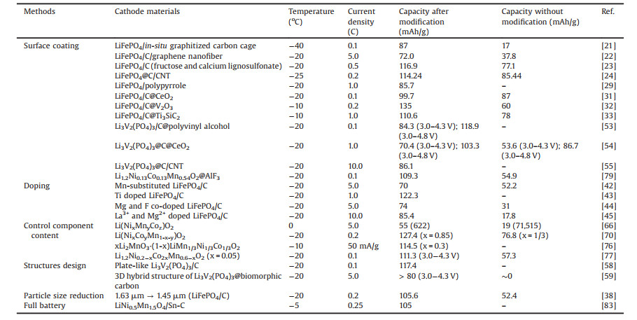
LiFePO4 with olivine structure has been the mainstream cathode material in LIBs as a result of its advantages, such as high discharge specific capacity (~170 mAh/g), stable structure, excellent cycle performance and high safety [13]. In theory, LiFePO4 exchanges Li+ with the electrolyte on all surfaces, but the actual Li+ can only move to the crystal in the [010] direction, which seriously affects the diffusion capacity of Li+ (~10-14cm2/s) [14, 15]. Meanwhile, LiFePO4 also has poor electronic conductivity (~10-9 S/cm) [16]. These shortcomings will be amplified as the electrochemical activity of the material decreases in cold environments, resulting in a sharp reduction in battery capacity. Therefore, the research on LiFePO4 mainly focuses on improving the extremely poor ion diffusion rate and electron conductivity at low temperatures. The optimizing methods are surface coating, particle size reduction, and doping.
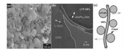
Surface coating is a useful method to enhance the low-temperature capacity of cathode materials. On the one hand, electron transport networks will be established to increase the conductivity of the cathode material [17, 18]. On the other hand, the material structure will be stabilized by reducing the polarization of the material during charging and discharging. Carbon coating in the surface coating is a relatively mature approach to optimize the electrochemical performance of LiFePO4. Firstly, at high temperature, carbon can not only form more pores in the pyrolysis process to promote the infiltration of electrolyte on the LiFePO4 but also effectively inhibit Fe2+ oxidation to enhance the purity of LiFePO4 phase [13, 15, 19, 20]. Secondly, a uniform and complete carbon coating can build a conductive network to enhance the surface conductivity of LiFePO4 particles. Finally, the coating of multiple carbon sources can not only improve the graphitization degree of the carbon but also establish a better conductive network through complementary advantages, thus optimizing the low-temperature performance of LiFePO4. Yao et al. [21] wrapped nano-sized LiFePO4 spheres with in-situ graphitized carbon cages, resulting in better electron conductivity (2.15×10⁻¹ S/cm) and excellent capacity (87 mAh/g vs. 17 mAh/g) in 1 mol/L LiPF6 ethylene carbonate (EC)-dimethyl carbonate (DMC)-ethyl methyl carbonate (EMC) (the volume ratio of the three is 1:1:1) electrolyte solution at -40 ℃. Xie et al. [22] used graphene nanofibers to form LiFePO4/C with a "bridge network" structure. The composite in 1 mol/L LiPF6 EC-DMC (the volume ratio of the two is 1:1) delivered the capacities of 92.8 mAh/g after 200 cycles at -20 ℃ and 1 C. Liu et al. [23] demonstrated that LiFePO4/C coated with fructose and calcium lignosulfonate had a capacity retention rate of 75.1% at -10 ℃ and 0.5 C in 1 mol/L LiPF6 EC-EMC-diethyl carbonate (DEC) (the volume ratio of the three is 3:3:4) electrolyte. The 3D carbon-nanotube-decorated nano-LiFePO4@C/CNTs designed by Wu et al. showed an excellent low-temperature property [24]. At -25 ℃ in 1 mol/L LiPF6 EC-DMC-DEC (the weight ratio of the three is 1:1:1) electrolyte, the capacity retention of this synthetic composite could achieve ~71.4% of that at 25 ℃. Fig. 1 shows the morphology of the LiFePO4@C/CNT composite. It displays that the improvement in low-temperature performance results from the synergy of the amorphous uniform carbon coating. The amorphous carbon is evenly coated on LiFePO4 nanoparticles, which improves the diffusion capacity of Li+ and enhances the stability of the interface of LiFePO4. Simultaneously, the carbon nanotubes connect the LiFePO4@C particles to form an optimal 3D conducting network in the entire electrode, thus cutting down the internal resistance and optimizing the low-temperature performance. Moreover, the method also alleviates the effect of low temperature on LiFePO4 working voltage. The middle discharge voltage of LFP@C/CNT (3.26 V) was higher than that of the pristine LFP (3.00 V), LFP@C (3.03 V) and LFP/CNT (3.09 V) at -25 ℃. This is because the co-coating of carbon and carbon nanotubes reduces the polarization of LiFePO4 at low temperatures, accelerates the electrochemical reaction, and thus increases its working voltage.

|
Download:
|
| Fig. 1. (a) HRPTEM image, (b) schematic structure diagram and (c) SEM image of the LiFePO4@C/CNT nanocomposite. Reproduced with permission [24]. Copyright 2013, John Wiley and Sons. | |
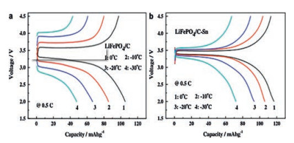
However, some studies have shown that excessive carbon coating can cause the production of Fe2P as a by-product, which seriously reduces the tap density of LiFePO4 and induces a declining actual specific capacity of LiFePO4 [25]. Therefore, some conductive polymers with similar mechanisms of carbon action are selected to modify the conductivity of LiFePO4, such as polyaniline and polypyridine [26, 27]. Compared with carbon, they have better compatibility with electrolytes, which can effectively adjust the polarity difference between LiFePO4 and electrolyte, promote the infiltration of electrolyte into active particles and lower the Rct [28]. Gao et al. [29] synthesized the 2.95% polypyrrole-coated LiFePO4 composite (LiFePO4/PPy) had a high capacity of 85.7 mAh/g at -20 ℃ and 1 C in 1 mol/L LiPF6 EC-DEC (the volume ratio of the two is 1:1) electrolyte. Furthermore, they also showed that the coating of Polypyrrole (2.95%) slowed the drop in discharge voltage caused by low temperatures, but too much PPy had the opposite effect. This is because PPy has no discharge voltage platform, which will inevitably affect the discharge platforms of LiFePO4/PPy composites. Moreover, metals or metal oxides have drawn high attention from researchers by reason of their excellent conductivity and simple preparation. Lin et al. [30] systematically researched the effect of Sn-coating on the electrochemical performance of LiFePO4/C and showed that Sn-coating was beneficial to enhance the low-temperature capacity of LiFePO4/C (Fig. 2). It is attributed to the fact that the Sn-coating increases the mutual contact between LiFePO4 particles, reduces the activation energy required to transport Li+ (42.76 kJ/mol vs. 81.02 kJ/mol), and thus promotes the rapid diffusion of Li+ at low temperature. At the same instant, the coating layer also inhibits the dissolution of Fe in the electrolyte and plays an effective role in protecting the active material. Yao et al. [31] reported that Li+ had better insertion/extraction capability in CeO2-coated LiFePO4 at low temperatures. This is by reason of the improved contact between the LiFePO4 and the current collector and particles, which alleviates the increase in Rct (606.5 Ω vs. 744.4 Ω) and delivers an excellent low-temperature capacity of 99.7 mAh/g after 30 cycles at -20 ℃ and 0.1 C in 1 mol/L LiPF6 EC-DMC (the volume ratio of the two is 1:1) electrolyte. Similarly, Jin et al. [32] coated highly conductive V2O3 (103 S/cm) on the external of LiFePO4 to promote Li+ transport in the LiFePO4 and raise the low-temperature capacity of LiFePO4/C (~135 mAh/g at -10 ℃ and 0.2 C in 1 mol/L LiPF6 EC-DEC (the weight ratio of the two is 1:1) electrolyte). In addition to the coating mentioned above, Cai et al. [33] showed that coating with 4 wt% Ti3SiC2 (TSC-4) was another effective tactic to enhance the poor low-temperature performance of LiFePO4/C. The crystal structure of Ti3SiC2 is a highly anisotropic hexagon and has a huge surface area. Ti3SiC2 can form a "plane-to-point" conduction mode between the original particles, increase the low electron transfer rate and make it compatible with the diffusion rate of Li+, thereby improving the low-temperature capacity of LiFePO4. The results showed that the TSC-4 kept capacity retention of 97.0% at -10 ℃ and 1 C after 100 cycles in 1 mol/L LiPF6 EC-DMC (the volume ratio of the two is 1:1) electrolyte (LiFePO4/C was 81.2%).

|
Download:
|
| Fig. 2. (a) Capacity of LiFePO4/C and (b) LiFePO4/C-Sn under different temperatures at 0.5 C. Reproduced with permission [30]. Copyright 2013, Elsevier. | |
Particle size reduction has a general mechanism of action in improving the low-temperature capacity for LiFePO4. Reducing the particle size can observably shorten the length of the diffusion path of Li+ and electrons, promote the lithium insertion/extraction process, and enhance the electron transfer speed to a certain extent [34, 35]. Meanwhile, the huge specific surface area of the small particles can make them fully get in touch with the electrolyte and promote the rapid diffusion of Li+ between the solid and the liquid phases [36]. Zhao et al. [37] proposed that the discharge capacity of carbon-coated LiFePO4 material would increase with the decrease of particle size at low temperatures. At -20 ℃ under 0.2 C, the capacity could be enhanced from 52.4 mAh/g to 105.6 mAh/g when the particle size diminished from 1.63 μm to 1.45 μm (1 mol/L LiPF6 in EC-DEC (the volume ratio of the two is 1:1) as the electrolyte). However, smaller particles not only produce more side reactions but also require a large amount of binder for binding, which will inevitably lead to a reduction in capacity [38]. Moreover, for the 1D diffusion of LiFePO4 in the [010] direction. Zhao et al. [39] prepared large-sized single-crystal LiFePO4 nanosheets with a high exposure ratio along the direction of [010] by controlling the thickness of the particle layer, as shown in Fig. 3. The shorter path lengths and the larger effective contact field with the electrolyte in the [010] direction are significantly improved the Li+ diffusivity (6.2×10⁻¹³cm2/s).

|
Download:
|
| Fig. 3. Schematic illustration of shortening the Li+ diffusion distance along the [010]. Reproduced with permission [39]. Copyright 2014, American Chemical Society. | |
The low-temperature capacity of LiFePO4 can also be increased by trace doping of elements. The fact that the doped ion is close to the iron ion radius does not induce a large change in the structure of the crystal. Proper doping can change the ratio of Fe3+/Fe2+, reduce the energy level of conduction bands and valence bands, and improve the conductivity of LiFePO4 [40]. Moreover, doping can promote the formation of phases and provide more Li+ vacancies, and thus optimize the electrochemical activity of LiFePO4 [41]. Zeng et al. [42] developed LiFe0.98Mn0.02PO4/C materials, which showed a high capacity of 70 mAh/g at -20 ℃ and 5 C in 1 mol/L LiPF6 EC-DMC-DEC-EMC (the volume ratio of the four is 1:1:1:1) electrolyte. The substitution of trace Mn2+ weakens the increase of potential difference between the charging and discharging voltage platforms, promotes the insertion and extraction of Li +, and thus enhances the electrochemical performance. Li et al. [43] announced that the LiFePO4/C with Ti in-situ doped had a discharge capacity of 26 mAh/g more than LiFePO4/C at -20 ℃ and 1 C in 1 mol/L LiPF6 EC-DEC (the volume ratio of the two is 1:1) electrolyte. Huang et al. [44] prepared LiFe0.92Mg0.08(PO4)0.99F0.03 electrode material co-doped with Mg and F by solid-phase method. The doped F rearranges the electron cloud in the PO43- to increase the electronic conductivity. The length of the Mg-O bond is shorter than that of the Fe-O, which broadens the diffusion channel of Li+ and improves the ion conductivity of LiFePO4. At -20 ℃ in 1 mol/L LiPF6 EC-DEC (the volume ratio of the two is 1:1) electrolyte, the specific capacities of the material were 109 (1 C), 94 (2 C), and 74 mAh/g (5 C). Zhang et al. [45] synthesized La and Mg-doped Li0.99La0.01Fe0.9Mg0.1PO4 composite electrode material by solution impregnation process and had a high low-temperature capacity, 56.6 mAh/g under -20 ℃ and at 50 C (1 mol/L LiPF6 in EC-DEC (the volume ratio of the two is 1:1) as the electrolyte). The results of electrochemical impedance experiments indicated that the ion doping, and carbon aerogel coatings improved the electronic conductivity of LiFePO4 (10-1 S/cm).
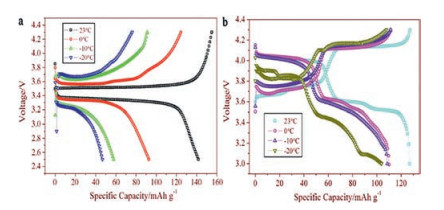
2.2. Li3V2(PO4)3 cathode materialLi3V2(PO4)3 has attracted great attention because of its good thermal stability, excellent ions mobility and high reversible capacity (~197 mAh/g) [46, 47]. Rui and co-workers reported that the low-temperature performance of Li3V2(PO4)3/C was remarkably exceeded that of LiFePO4/C in 1 mol/L LiPF6 EC-DMC (the weight ratio of the two is 1:1) electrolyte [48]. The initial charge and discharge curves of Li3V2(PO4)3/C and LiFePO4/C at diverse temperatures are illustrated clearly in Fig. 4. At -20 ℃, Li3V2(PO4)3/C has a stable and reversible discharge capacity of 108.1 mAh/g versus LiFePO4/C is only 45.4 mAh/g. Obviously, at low temperatures, Li3V2(PO4)3 has better capacity stability than LiFePO4. It may be due to the 3D network Li+ channels of Li3V2(PO4)3 (LVP) which contribute to Li+ diffusion, resulting in excellent Li+ intercalation/deintercalation reversibility and structural stability [49, 50]. To further improve the low-temperature capacity of Li3V2(PO4)3, scholars have adopted the strategies of surface coating and designing structures.

|
Download:
|
| Fig. 4. The initial charge and discharge curves of (a) LiFePO4/C and (b) Li3V2(PO4)3/C at diverse temperatures (23, 0, -10 and -20 ℃) and 0.3 C. Reproduced with permission [48]. Copyright 2011, Elsevier. | |
The mechanism of the surface coating to optimize the low-temperature performance of Li3V2(PO4)3 is the same as LiFePO4, which raises the electrical conductivity and reduces the polarization to increase the low-temperature capacity of materials [51, 52]. The Li3V2(PO4)3/C coated with polyvinyl alcohol prepared by Qiao et al. provided a remarkably initial discharge capacity of 84.3 mAh/g (3.0-4.3 V) and 118.9 mAh/g (3.0-4.8 V) in the electrolyte 1 mol/L LiPF6 EC-DMC (the weight ratio of the two is 1:1) at -20 ℃, 0.1 C [53]. Cai et al. [54] proved that CeO2 (2%) significantly reduced the Rct (from 491.8 Ω to 119.5 Ω) and increase the capacity (70.4 mAh/g (3.0-4.3 V); 103.3 mAh/g (3.0-4.8 V)) of Li3V2(PO4)3/C at -20 ℃ and 1 C. Tai et al. [55] demonstrated that the Li3V2(PO4)3 coated with glucose and carbon nanotubes showed an excellent low-temperature capacity, 86.1 mAh/g between 3.0 V and 4.3 V at -20 ℃, 10 C (1.2 mol/L LiPF6 in EC-DMC-EMC (the volume ratio of the three is 1:1:1) as the electrolyte). The synergistic effect of two carbon sources prevents particle agglomeration and provides remarkable electron and Li+ transport paths.
The structure design can dramatically enhance the low-temperature capacity of the electrode materials. For example, the large specific surface field of the flat plate structure raises the contact area between the electrode and the electrolyte and promotes the rapid diffusion of Li+ between them [56], and the mixing of various structures can efficiently avoid the self-aggregation of low-dimensional nanomaterials and improve the tap density [57]. The plate-shaped Li3V2(PO4)3/C material with a thickness of 100 nm and a size of 1-2 μm prepared by Teng et al. had a specific capacity of 120.7 mAh/g at -20 ℃ and 0.1 C (1 mol/L LiPF6 in EC-DMC (the volume ratio of the two is 1:1) as the electrolyte), which is 95.3% of the capacity at room temperature [58]. Cheng et al. [59] designed a novel 3D structure of Li3V2(PO4)3@biomorphic carbon that can operate at low temperatures (LVP@HPBC). As shown in Fig. 5, after calcination, the gelatinous layer on one side of the agar was carbonized into a 2D carbon layer, and the long beard on the other side was converted into a 1D carbon tube and 0D carbon-coated LVP particles, thus forming this three-dimensional hybrid structure. The synergistic effect produced by the combination of 0D, 1D and 2D carbon provides fast ion transport, high conductivity and strong structural stability of Li3V2(PO4)3, hence obtaining high low-temperature capacity (105 mAh/g at -20 ℃ in 1 mol/L LiPF6 EC-DMC-EMC (the volume ratio of the three is 1:1:1) electrolyte).

|
Download:
|
| Fig. 5. The morphology of the LVP@HPBC. Reproduced with permission [59]. Copyright 2017, John Wiley and Sons. | |
Nickel-cobalt-manganese ternary cathode material (NMC) combines the advantages of LiNiO2, LiCoO2 and LiMnO2 ternary layered materials, namely, it has a high reversible specific capacity, good cycling stability and low toxicity [60-63]. Current research on low-temperature capacity performance mainly focuses on increasing the diffusion kinetics of Li+ by controlling the ratio of three metal ions (Ni, Co, Mn).
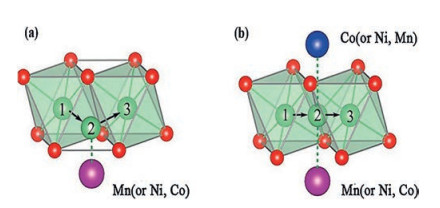
In the layered structure of NMC, Li+ has two diffusion paths, namely, tetrahedral path and oxygen dumbbell path [64, 65]. In the early stage of charging, Li+ is inclined to choose oxygen dumbbell hopping, and tetrahedral position hopping begins to dominate when the Li+ extracted exceeds 1/3, as shown in Fig. 6. In Fig. 6a, When the Li+ diffuses to position 2, the distance between Li and O atoms will affect the diffusion activation energy of Li+. In Fig. 6b, the electrostatic interaction of transition metal cations on Li+ influences the work done by the system to transfer Li+. Consequently, the Li+ diffusion kineticsdepend on the Li slab space and the type and valence state of transition metals. Based on this, Cui et al. [66] indicated that Li(Ni0.6Mn0.2Co0.2)O2 had the highest diffusion coefficient of Li+ and a small dependence on temperatures, with a capacity of 55 mAh/g at 0 ℃, 5 C. As Ni content rises in NMC material (532-622-71515-811), average ions radius enhances (Ni2+ (0.069 nm) > Ni3+ (0.056 nm) > Co3+ (0.054 nm) > Mn4+ (0.053 nm)). However, the increase of Ni valence will lead to a decrease in the average radius of Ni. These two conditions restrict each other, and there is an equilibrium point near 622, which maximizes the space of the Li slab space in 622, thus optimizing the low-temperature capacity property of NMC.

|
Download:
|
| Fig. 6. (a) Tetrahedral position pathway (b) and oxygen dumbbell pathway for Li+ diffusion in NMC layered structure. Reproduced with permission [66]. Copyright 2016, John Wiley and Sons. | |
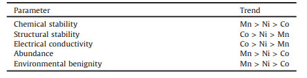
In NMC, Ni, Co, and Mn have an obvious ternary synergistic effect, and each has its advantages and disadvantages [67]. The Mn3+/4+ band lies above the Ni2+/3+ band, and Mn3+ tends to be oxidized to Mn4+ during the synthesis process by reducing Ni3+ to Ni2+ [68]. Thus, Mn4+ helps to incorporate Ni as a stable Ni2+ into NMC and is used as a structural stabilizer without participating in the charge-discharge processes. However, Mn readily migrates into the lithium plane due to the smaller octahedral site stability energy (OSSE) (Co3+ (-2.13 Δo) > Ni3+ (-1.35 Δo) > Mn3+ (-0.42 Δo)), which changes the crystal structure from a layered to a spinel structure and leads to a significant reduction in capacity. In contrast, Co does not occur such migration and can effectively keep the layered structure in a steady state due to the large OSSE. But the disadvantage of Co is that it is expensive and harmful to the environment. The properties of Ni are between Mn and Co (Table 2), which can both increase the capacity of the material and stabilize the structure [68, 69]. Yoon et al. [70] also showed that the high nickel content in NMC can greatly increase the low-temperature capacity of NMC. The capacity of Li(Ni0.85Co0.075Mn0.075)O2 is 127.4 mAh/g, while Li(Ni1/3Co1/3Mn1/3)O2 is 76.8 mAh/g at -20 ℃ and 0.2 C (both are in 1.2 mol/L LiPF6 EC-EMC (the volume ratio of the two is 3:7) electrolyte).
|
|
Table 2 Comparison of the characteristics of Mn, Co and Ni in NMC. Reproduced with permission [68]. Copyright 2020, Springer Nature. |
The Li-rich cathode materials xLi2MnO3·(1-x)LiMO2 (M=Ni, Co, Mn) (LLR) are more attractive than existing commercial cathode materials due to their higher specific capacity (more than 250 mAh/g, 4.6 V) and low cost [71, 72]. The high discharge specific capacity of LLR benefits from their unique structural components, namely layered Li2MnO3 and MnO2 [73]. When the charging potential is 4.5 V, Li2MnO3 is activated [74]. Meanwhile, Li+ escapes from the lithium layer and produces O vacancies, and forms MnO2 subsequently. Therefore, a delithiation and deoxygenation platform is created to increase capacity. At present, the research on its low-temperature performance is still in the exploration stage, and the improvement methods mainly include controlling component content and surface coating.
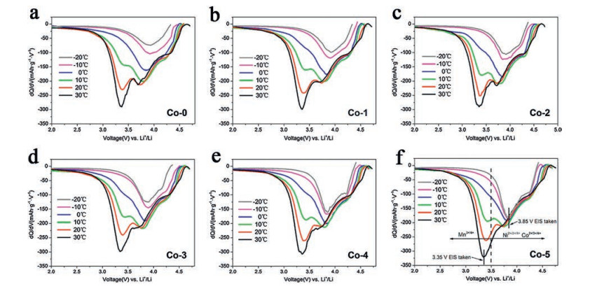
In 2014, Qiu et al. [75] explored the low-temperature properties of Li[Li0.144Ni0.136Co0.136Mn0.544]O2. The results showed that the initial coulombic efficiency decreased from 91.5% to 74.2% with the applied charging/discharging temperature from 50 ℃ to 0 ℃, which indicated that the charge and discharge asymmetry of the LLR increased as the temperature decreased. Furthermore, through the analysis of the dQ/dV curves, it was found that the peak at around 3.3 V obviously relied on the temperature, and the peak was assigned to the reaction process in which Li+ was embedded into MnO2 component. This means that the process of lithium re-intercalation into MnO2 derived from the Li2MnO3 component is an important reason for the degradation of the low-temperature properties of LLR. Similarly, Yu and co-workers also indicated that the content of Li2MnO3 (x) had a certain effect on the low-temperature performance of xLi2MnO3·(1-x)LiMn1/3Ni1/3Co1/3O2, mainly the electrical conductivity [76]. x=0.3 ameliorated the layered structure of the compound and reduced the mixing of Li+/Ni+ cations to a minimum, thus the composite material exhibited the largest conductivity (4.36×10⁻⁶ S/cm). In addition to regulating the composition of Li2MnO3, Kou et al. [77] pointed out that trace Co could reduce the sensitivity of LLR to temperature. As shown in Fig. 7, compared with other contents, the reduction peak of Ni4+ or Co4+ at 3.85 V of the sample with high Co content is hardly affected by temperatures. This means that trace amounts of Co can reduce the charge transfer activation energy at low temperatures by promoting the interface reduction reaction of Ni4+ or Co4+, thereby optimizing the low-temperature performance of the LLR (the capacity retention rate of Li1.2Ni0.2-xCo2xMn0.6-xO2 at x=0.05 is 17.3% higher than x=0 at -20 ℃ and 0.1 C (1 mol/L LiPF6 in EC-EMC (the volume ratio of the two is 1:1) as the electrolyte).

|
Download:
|
| Fig. 7. dQ/dV plots of the Li1.2Ni0.2-xCo2xMn0.6-xO2 ((a) x = 0, (b) 0.01, (c) 0.02, (d) 0.03, (e) 0.04, (f) 0.05) cells under different temperatures. Copied with permission [77]. Copyright 2015, American Chemical Society. | |
Surface coating can enhance the low-temperature capacity of LLR to some extent. Zhao et al. [78] showed that coating AlF3 provided a feasible method for the application of low-temperature LLR. Firstly, the dense AlF3 layer builds fast Li+ transport channels for adjacent active materials and reduces the side reactions between the electrolyte and the active materials. Secondly, AlF3 promotes electrochemical performance by changing the working voltage of LLR. The coating of AlF3 enables the sample to form an oxidation peak at 2.8 V that does not exist in the pure sample, thus forming the spinel structure on the surface of LLR. And the electron migration rate in the spinel structure is higher than that in layered structure [79], which is beneficial to charge transfer reaction. Finally, the presence of LiAlO2 enhances the diffusion kinetics of Li+. The Li1.2Ni0.13Co0.13Mn0.54O2 coated with 2% AlF3 coating prepared by this research group displayed a higher discharge capacity than the original sample at low temperatures (161.9 mAh/g vs. 144.1 mAh/g at -10 ℃, 109.3 mAh/g vs. 54.9 mAh/g at -20 ℃ (0.1 C)).
2.5. LiMn2O4 cathode materialThe spinel structure of the LiMn2O4 cathode material has the advantages of non-toxicity and low cost due to the absence of Co. Nevertheless, the Jahn-Teller effect can cause the phase transformation of LiMn2O4 (cubic system-tetragonal system) and induce a large change in the volume during the cycling process, thereby reducing the capacity of the LiMn2O4 [80, 81]. In the process of the discharge, Mn2+ and Mn4+ produced by the disproportionation reaction of Mn ions (2Mn3+=Mn2++Mn4+) are easily soluble in the electrolyte, leading to the reduction of cathode active materials and the attenuation of capacity. The low-temperature performance of LiMn2O4 has been rarely reported. Shen et al. [82] investigated the phase transition in spinel LiMn2O4 by using powder synchrotron radiation diffraction. The study showed that doping Co in the [Mn2O4] framework could increase the average valence state of Mn, reduce the concentration of Mn3+, and play a role in suppressing Jahn Teller distortion. Elia and co-workers explored the low-temperature performance of a full battery (LiNi0.5Mn1.5O4/Sn-C) [83]. The study not only pointed out that the sudden drop in battery capacity in cold temperatures is due to the cold accelerates the polarization of the electrode and seriously hinders the Li-Sn alloying process. And it also showed that this specially configured battery had a higher low-temperature capacity, which is 105 mAh/g (75% of theoretical value) after 200 cycles at -5 ℃ and 0.25 C in 1 mol/L LiPF6 EC-DEC-DMC (1:1:1) electrolyte.
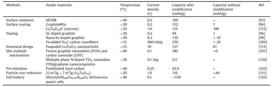
3. Methods for enhancing the low-temperature capacity of anode materialsThe anode material of a LIB is usually accompanied by the rapid increase of Rct and the difficulty of Li+ embedding during the low-temperature charge-discharge processes [4, 11]. In that case, the anode polarization is serious and a large amount of metal lithium precipitates on the surface [84]. This metal lithium easily reacts with the electrolyte to form non-reactive sediment, which leads to the decrease of Li+ concentration in the electrolyte and the attenuation of the capacity. In this review, anode materials are divided into carbon and non-carbon materials to discuss optimizing methods (Table 3).
|
|
Table 3 Low-temperature capacity of different anode materials. |
Graphite is the most commonly used carbon anode material for LIBs under subzero temperature conditions. In cold environments, the poor lithium intercalation/deintercalation ability of graphite is related to the high Rct at graphite electrode interface, the lowered Li+ diffusion capability within graphite layers, and the instability of the solid electrolyte interface (SEI) film [9, 85, 86]. Furthermore, the graphite electrode has a low operating voltage (less than 0.2 V vs. Li/Li+), which can easily structure a lithium coating and causes serious safety issues, especially at low temperatures [87, 88]. Heretofore, the low-temperature performance is mainly optimized by surface oxidation, surface coating, doping, mix multiple mechanisms, and pre-lithiation.
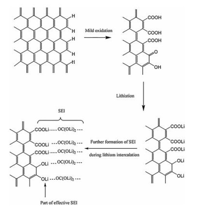
There is a given number of dangling bonds and groups on the graphite surface, and the carbon-hydrogen bonds block Li+ from intercalating into the graphite structure to inhibit the lithium storage process [89]. The surface oxidation can convert the carbon-hydrogen bond into a carboxyl group, and the lithiated carboxyl can form a lithium salt on the electrode surface and act as a component of the SEI film, thereby increasing the lithium content in the SEI film and reducing the impedance (illustrated in Fig. 8). Simultaneously, the oxidation process also produces nanochannels and micropores, which can serve as reversible lithium storage sites to promote the insertion/extraction of Li+ [90, 91]. Mao et al. [92] reported that K2FeO4 oxidation formed some mesoscopic channels on the graphite surface, which promoted the infiltration of electrolyte and graphite. Whereby, the charge transfer impedance and the diffusion impedance were reduced, as shown in Fig. 9. Zhao et al. [93] demonstrated that oxidation modification raised the average interlayer distance of Mesocarbon Microbeads (MCMB) and promoted Li+ insertion kinetics, which extraordinarily ameliorated the capacity of MCMB at -40 ℃ (100 mAh/g, the original MCMB has almost no capacity at -40 ℃ and 0.2 C).

|
Download:
|
| Fig. 8. Changes of chemical bonds on graphite surface after mild oxidation. Reproduced with permission [89]. Copyright 2006, Elsevier. | |

|
Download:
|
| Fig. 9. Nyquist plots of graphite oxidized by K2FeO4 (NG: natural graphite, OG: oxidized graphite). Copied with permission [92]. Copyright 2006, Elsevier. | |
The low-temperature properties of graphite materials are improved after surface coating, which may be caused by (1) stabilized the SEI film [94]. Defects on the graphite surface are likely to cause the SEI to rupture, which leads to the reaction between graphite and electrolyte and accelerates the stripping of graphite structure. The coating can be adsorbed on the defective position and cover it to improve the stability of the SEI. (2) The coating of metal or metal oxide can greatly lower the resistance between graphite particles and heighten the intercalation dynamics of Li+ [95]. Nobili et al. [96] used tin-coated graphite as the anode. Compared with the uncoated material, the SEI resistance and Rct were reduced by 3 and 10 times at -20 ℃ and 0.2 C (1 mol/L LiPF6 EC-DEC-DMC (1:1:1) as the electrolyte). It showed that tin coating reduced the polarization of the battery in a cold environment. Friesen et al. [97] announced that a small amount of surface coating of Al2O3 fully prevented the obvious risk of lithium metal deposition.
The doping of metal nanoparticles can improve the desolvation of Li+ and enhance the internal conductivity of carbon materials, thus increasing low-temperature capacity [98]. The excellent low-temperature performance of the Sn doped oxidized graphite electrode was ascribed to the increase in the internal conductivity of the metal-dispersed powder electrode (94 mAh/g at -30 ℃ and 0.2 C in LiPF6 1 mol/L in EC-DEC-DMC (1:1:1) electrolyte) [96]. Similar to it, Yan and co-workers synthesized a Sn/expanded graphite (Sn/EG) composite material with a close-packed layered structure [99]. And the experimental results showed that as the temperature decreased, the Rct of Sn/EG increased less rapidly than graphite and exhibited faster Li+ intercalation kinetics, which helped to improve low-temperature capacity. At -20 ℃ in 1 mol/L LiPF6 EC-DMC (the volume ratio of the two is 1:1) electrolyte, the capacity of Sn/EG is 130 mAh/g was better than graphite (< 10 mAh/g). Li et al. [100] designed a Fe-doped Fe3C carbon nanofiber composite, which showed a high capacity of 250 mAh/g after 55 cycles at -15 ℃ and 400 mA/g in 1 mol/L LiPF6 EC-EMC-DMC (the volume ratio of the three is 1:1:1) electrolyte. The introduction of Fe enhances the conductivity of Fe3C and reduces the polarizability of the electrode surface.
In addition to the above methods, preparing composite electrodes and pre-lithiation can also improve the low-temperature capacity of graphite. Xu et al. [101] developed a novel electrode composed of carbon nanotubes and thin graphite sheets with holes. The holes in the graphite nanosheets facilitated the transport of Li+ and the CNT prevented the restack of graphite sheets, thus improving the low-temperature performance (180 mAh/g at -40 ℃ and 0.1 C in 1 mol/L LiPF6 EC-EMC-DMC (the volume ratio of the three is 1:1:1) electrolyte). Liu et al. [102] built a LIB with an outstanding low-temperature performance by an ordinary pre-lithiation strategy. The initial Li+ extracted from Li3V2(PO4)3 was used to pre-harden hard carbon. The self-formed Li3V2(PO4)3 was used as the cathode and the pre-lithiated hard carbon as the anode to form 4 V LIB with a high capacity retention rate of over 67% at -40 ℃, which was much better than traditional LIBs.
3.2. Non-carbon materialsUp to now, there has been less research on the low-temperature operation of non-carbon anode materials, mainly including Li 4Ti5O12, Rutile-TiO2 and Si-based materials. The methods for enhancing the low-temperature capacity of these three anode materials are summarized below.
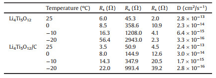
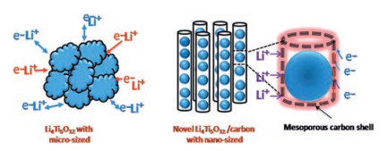
The spinel-type Li4Ti5O12 is a potential anode material for LIBs [103]. Compared with graphite anode materials, Li4Ti5O12 has good Li+ intercalation/deintercalation reversibility and displays no structural transition during the cycle [104, 105]. Furthermore, it possesses a high working voltage of 1.55 V (vs. Li/Li+), which can stay away from the formation of lithium dendrites and partly ensure the security of LIBs [106-108]. Nevertheless, its poor electronic conductivity (< 10-13 S/cm) and sluggish Li+ diffusion coefficient (10-9~10-13cm2/s) severely limit its electrochemical kinetics, particularly at low temperatures [109, 110]. At present, the low-temperature capacity is mainly improved by reducing particle size, surface coating and structural design. Pohjalainen et al. [111] researched on the low-temperature property of two different sizes of Li4Ti5O12 (~150 nm vs. ~225 nm) and showed that small particle size and large surface area were beneficial to the capacity (110 mAh/g vs. 84 mAh/g at -20 ℃ and 1 C in 1 mol/L LiPF6 EC-DMC (the volume ratio of the two is 1:1) electrolyte). The small particles form secondary aggregates with a larger specific surface area (22 m2/g vs. 7 m2/g), which not only increases the tap density of Li4Ti5O12 (970 g/dm3 vs. 670 g/dm3) but also promotes the lithium insertion/extraction process. Yuan and co-workers demonstrated that the capacity of sucrose-coated Li4Ti5O12 (Li4Ti5O12/C) (119 mAh/g) was higher than the original Li4Ti5O12 (108 mAh/g) at -20 ℃ and 1 C in 1 mol/L LiPF6 EC-DMC (the volume ratio of the two is 1:1) electrolyte [112]. This is since the carbon coating averts the direct contact of Li4Ti5O12 with the electrolyte and improves the compatibility. As a result, the impedance of Li4Ti5O12 is significantly reduced and the diffusion rate of Li+ is increased, as shown in Table 4. Peng et al. [113] designed a novel peapod-like Li4Ti5O12 composite architecture with excellent low-temperature performance. Fig. 10 schematically illustrates that the synergy effect between the active-material core and the carbon fiber shell improves the kinetics of Li+. The internal Li4Ti5O12 nanoparticles with a diameter of 20-30 nm shorten the diffusion path of Li+ and lower the resistance. The external core-shell connects Li4Ti5O12 nanoparticles to further enhance the conductivity of lithium ions and electrons. For this reason, Li4Ti5O12 in 1 mol/L LiPF6 EC-DEC (the volume ratio of the two is 1:1) electrolyte showed a higher coulomb efficiency of ~99% after 500 cycles at -25 ℃ and 10 C.
|
|
Table 4 Impedance parameters of Li4Ti5O12 and Li4Ti5O12/C. Copied with permission [112]. Copyright 2010, Elsevier. |

|
Download:
|
| Fig. 10. Electron-transfer pathways of the peapod-like Li4Ti5O12 composite. Reproduced with permission [113]. Copyright 2016, Royal Society of Chemistry. | |
Rutile-TiO2 is an alternative material for carbonaceous anodes with high capacity (335 mAh/g), low cost, non-toxic and other characteristics [114]. The optimization method of low-temperature capacity is mainly a mixture of multiple mechanisms. At room temperature, it is difficult to insert lithium into bulk rutile, but it can be partially inserted in nano-scale rutile material [115, 116]. There are two different paths for the insertion/extraction of Li+ in rutile-TiO2, showing a high anisotropy (along the ab-plane (DLi+=10-14cm2/s) and via the c-axis (DLi+=10-6cm2/s)) [117, 118]. Marinaro et al. [119] proposed that high-surface nano-sized rutile TiO2 (180 m2/g) had a high low-temperature capacity (77 mAh/g) inside a potential window of 0.1–3 V at -40 ℃ and 0.2 C (1 mol/L LiPF6 in EC-DMC-DEC (the volume ratio of the three is 1:1:1) as the electrolyte). It can be seen that TiO2 is a promising low-temperature non-carbon anode material. Li et al. [120] designed an N-doped TiO2/TiN/graphene multiple-phase composite using a variety of mixing multiple mechanisms, which exhibited a high reversible capacity at low temperatures (211 mAh/g at -20 ℃ and 0.1 A/g in 1 mol/L LiPF6 EC-DMC (the volume ratio of the two is 1:1) electrolyte). The reasons are as follows: (1) TiO2 nanotubes promote the diffusion kinetics of Li+ by shortening the path. (2) The introduction of N and TIN increased the conductivity of the TiO2. (3) The large specific surface area of the graphene sheets promotes electron transfer by reducing the resistance between TiO2 nanotubes.
Other than two intercalation-type anodes, the alloy-type silicon-based anode materials are also used in low-temperature applications. Silicon-based anodes are gradually replacing current commercial graphite anodes due to the high specific capacity of silicon (Li4.4Si is 4212 mAh/g) [121, 122]. However, the material will undergo a huge volume expansion during the alloying process, resulting in a sharp decline in capacity [123, 124]. Markevich et al. [125] compared the cycle performance of graphite composite anode and silicon anode in 1 mol/L LiPF6 FEC-DMC (1:4) electrolyte and studied the low-temperature capacity performance of amorphous monolithic columnar silicon anode. The capacity of the silicon anode hardly decreases in the range of -20 ℃ to -30 ℃. Subburaj et al. [126] developed and tested a 1Ah lithium-ion pouch battery with silicon as the anode and LiNi0.8Co0.15Al0.05O2 as the cathode. At -40 ℃ in 1 mol/L LiPF6 EC-DMC-DEC (the volume ratio of the three is 1:3:1) electrolyte, the cell still retains 50% of the initial capacity after 60 cycles (C/15 charge and C/10 discharge rate). These reports prove that silicon-based materials are very attractive anode materials for low-temperature LIB, but further improvements are needed to improve low-temperature performance.
4. Conclusion and prospectiveThe low-temperature performance of LIBs is a critical factor restricting the application and the low-temperature capacity of cathode and anode materials plays a decisive role. Throughout all studies, reducing the particle size, surface coating and doping have a general mechanism of action in enhancing the low-temperature capacity for various electrode materials. The smaller particle can significantly shorten the diffusion path distance of Li+ and improve the lithium insertion/extraction process. Surface coating is beneficial to improve the surface conductivity of electrode materials and reduce contact resistance. Doping can form vacancies in the lattice structure and broaden the ion diffusion channel to promote the mobility of Li+ and electrons in the material. By summarizing, it is found that non-carbon anode materials show a higher low-temperature capacity than carbon materials. However, there are few studies on them, so research should be strengthened in the future. In addition to continuing to modify the existing materials to reduce the diffusion resistance of Li+, some electrode materials with excellent conductivity and short Li+ diffusion distance can also be developed to decrease the reduction of capacity caused by low temperature. In the end, we should also pay attention to the overall optimization of the battery system, that is, the correct matching of cathodes and anodes, so that the low-temperature performance of the battery can be further increased.
Declaration of competing interestThe authors report no declarations of interest.
AcknowledgmentsThis work was supported by the National Natural Science Foundation of China (NSFC, Nos. 51772205, 51572192, 51772208, 51472179) and the General Program of Municipal Natural Science Foundation of Tianjin (Nos. 17JCYBJC17000, 17JCYBJC22700).
| [1] |
J.B. Goodenough, K. Park, J. Am. Chem. Soc. 135 (2013) 1167-1176. DOI:10.1021/ja3091438 |
| [2] |
N. Zhang, X. Li, T. Hou, et al., Chin. Chem. Lett. 31 (2020) 1221-1225. DOI:10.1016/j.cclet.2019.09.050 |
| [3] |
M.C. Smart, B.V. Ratnakumar, L.D. Whitcanack, et al., Int. J. Energy Res. 34 (2010) 116-132. DOI:10.1002/er.1653 |
| [4] |
S.S. Zhang, K. Xu, T.R. Jow, J. Power Sources 115 (2003) 137-140. DOI:10.1016/S0378-7753(02)00618-3 |
| [5] |
G.T.K. Fey, Y.Y. Lin, K.P. Huang, et al., Adv. Mater. Res. 415- 417 (2011) 1572-1585. |
| [6] |
J. Fan, J. Power Sources 117 (2003) 170-178. DOI:10.1016/S0378-7753(03)00354-9 |
| [7] |
Y. Ji, Y. Zhang, C. Wang, J. Electrochem. Soc. 160 (2013) A636-A649. DOI:10.1149/2.047304jes |
| [8] |
S.S. Zhang, K. Xu, T.R. Jow, Electrochim. Acta 49 (2004) 1057-1061. DOI:10.1016/j.electacta.2003.10.016 |
| [9] |
A. Senyshyn, M.J. Mühlbauer, O. Dolotko, H. Ehrenberg, J. Power Sources 282 (2015) 235-240. DOI:10.1016/j.jpowsour.2015.02.008 |
| [10] |
G. Zhu, K. Wen, W. Lv, et al., J. Power Sources 300 (2015) 29-40. DOI:10.1016/j.jpowsour.2015.09.056 |
| [11] |
J. Hou, M. Yang, D. Wang, J. Zhang, Adv. Energy Mater. (2020) 1904152. |
| [12] |
P. Suresh, A.K. Shukla, N. Munichandraiah, J. Appl. Electrochem. 32 (2002) 267-273. DOI:10.1023/A:1015565404343 |
| [13] |
J. Wang, X. Sun, Energy Environ. Sci. 5 (2012) 5163-5185. DOI:10.1039/C1EE01263K |
| [14] |
P.P. Prosini, M. Lisi, D. Zane, M. Pasquali, Solid State Ion. 148 (2002) 45-51. DOI:10.1016/S0167-2738(02)00134-0 |
| [15] |
L. Yuan, Z. Wang, W. Zhang, et al., Energy Environ. Sci. 4 (2011) 269-284. DOI:10.1039/C0EE00029A |
| [16] |
Y.N. Xu, S.Y. Chung, J.T. Bloking, Y.M. Chiang, W.Y. Ching, Electrochem. Solid State Lett. 7 (2004) A131-A134. DOI:10.1149/1.1703470 |
| [17] |
Z. Chen, Y. Qin, K. Amine, Y.K. Sun, J. Mater. Chem. 20 (2010) 7606. DOI:10.1039/c0jm00154f |
| [18] |
P. Guan, L. Zhou, Z. Yu, et al., J. Energy Chem. 43 (2020) 220-235. DOI:10.1016/j.jechem.2019.08.022 |
| [19] |
Q. Liu, S. Liao, H. Song, Z. Liang, J. Power Sources 211 (2012) 52-58. DOI:10.1016/j.jpowsour.2012.03.090 |
| [20] |
Y. Kadoma, J. Kim, K. Abiko, et al., Electrochim. Acta 55 (2010) 1034-1041. DOI:10.1016/j.electacta.2009.09.029 |
| [21] |
B. Yao, Z. Ding, J. Zhang, X. Feng, L. Yin, J. Solid State Chem. 216 (2014) 9-12. DOI:10.1016/j.jssc.2014.04.023 |
| [22] |
D. Xie, G. Cai, Z. Liu, et al., Electrochim. Acta 217 (2016) 62-72. DOI:10.1016/j.electacta.2016.09.058 |
| [23] |
G. Wu, N. Liu, X. Gao, et al., Appl. Surf. Sci. 435 (2018) 1329-1336. DOI:10.1016/j.apsusc.2017.11.276 |
| [24] |
X. Wu, Y. Guo, J. Su, et al., Adv. Energy Mater. 3 (2013) 1155-1160. DOI:10.1002/aenm.201300159 |
| [25] |
R. Dominko, M. Bele, M. Gaberscek, et al., J. Electrochem. Soc. 152 (2005) A607-A610. DOI:10.1149/1.1860492 |
| [26] |
Y. Wang, Y. Wang, E. Hosono, K. Wang, H. Zhou, Angew. Chem. Int. Ed. 47 (2008) 7461-7465. DOI:10.1002/anie.200802539 |
| [27] |
K.S. Park, S.B. Schougaard, J.B. Goodenough, Adv. Mater. 19 (2007) 848-851. DOI:10.1002/adma.200600369 |
| [28] |
W. Chen, Y. Huang, L. Yuan, J. Electroanal. Chem. 660 (2011) 108-113. DOI:10.1016/j.jelechem.2011.06.013 |
| [29] |
Y. Gao, Int. J. Electrochem. Sci. 14 (2019) 3408-3417. |
| [30] |
Y. Lin, Y. Lin, T. Zhou, et al., J. Power Sources 226 (2013) 20-26. DOI:10.1016/j.jpowsour.2012.10.074 |
| [31] |
J. Yao, F. Wu, X. Qiu, N. Li, Y. Su, Electrochim. Acta 56 (2011) 5587-5592. DOI:10.1016/j.electacta.2011.03.141 |
| [32] |
Y. Jin, C.P. Yang, X.H. Rui, T. Cheng, C.H. Chen, J. Power Sources 196 (2011) 5623-5630. DOI:10.1016/j.jpowsour.2011.02.059 |
| [33] |
G. Cai, R. Guo, L. Liu, et al., J. Power Sources 288 (2015) 136-144. DOI:10.1016/j.jpowsour.2015.04.129 |
| [34] |
C.R. Sides, C.R. Martin, Adv. Mater. 17 (2005) 125-128. DOI:10.1002/adma.200400517 |
| [35] |
B. Zou, H. Wang, Z. Qiang, et al., Electrochim. Acta 196 (2016) 377-385. DOI:10.1016/j.electacta.2016.03.017 |
| [36] |
B. Ellis, H.P. Subramanya, Y.H. Rho, et al., Faraday Discuss. 134 (2007) 119-141. DOI:10.1039/B602698B |
| [37] |
N. Zhao, Y. Li, X. Zhao, X. Zhi, G. Liang, J. Alloys Compd. 683 (2016) 123-132. DOI:10.1016/j.jallcom.2016.04.070 |
| [38] |
P.G. Bruce, B. Scrosati, J. Tarascon, Angew. Chem. Int. Ed. 47 (2008) 2930-2946. DOI:10.1002/anie.200702505 |
| [39] |
Y. Zhao, L. Peng, B. Liu, G. Yu, Nano Lett. 14 (2014) 2849-2853. DOI:10.1021/nl5008568 |
| [40] |
K.L. Harrison, C.A. Bridges, M.P. Paranthaman, et al., Chem. Mater. 25 (2013) 768-781. DOI:10.1021/cm303932m |
| [41] |
Z. Hua, X. Zhang, X. Feng, et al., Chin. Chem. Lett. 30 (2019) 792-796. DOI:10.1016/j.cclet.2018.11.004 |
| [42] |
L. Zeng, Q. Gong, X. Liao, et al., Chin. Sci. Bull. 56 (2011) 1262-1266. DOI:10.1007/s11434-010-4097-0 |
| [43] |
Z. Li, X. Ren, Y. Zheng, et al., Ionics 26 (2020) 1599-1609. DOI:10.1007/s11581-019-03408-4 |
| [44] |
Y. Huang, Y. Xu, X. Yang, Electrochim. Acta 113 (2013) 156-163. DOI:10.1016/j.electacta.2013.09.044 |
| [45] |
H. Zhang, Y. Xu, C. Zhao, X. Yang, Q. Jiang, Electrochim. Acta 83 (2012) 341-347. DOI:10.1016/j.electacta.2012.07.128 |
| [46] |
M.Y. Saidi, J. Barker, H. Huang, J.L. Swoyer, G. Adamson, J. Power Sources 119- 121 (2003) 266-272. |
| [47] |
S. Yin, H. Grondey, P. Strobel, H. Huang, L.F. Nazar, J. Am. Chem. Soc. 125 (2003) 326-327. DOI:10.1021/ja028973h |
| [48] |
X.H. Rui, Y. Jin, X.Y. Feng, L.C. Zhang, C.H. Chen, J. Power Sources 196 (2011) 2109-2114. DOI:10.1016/j.jpowsour.2010.10.063 |
| [49] |
R. Qin, Y. Wei, T. Zhai, H. Li, J. Mater. Chem. A 6 (2018) 9737-9746. DOI:10.1039/C8TA01124A |
| [50] |
X.H. Rui, N. Ding, J. Liu, C. Li, C.H. Chen, Electrochim. Acta 55 (2010) 2384-2390. DOI:10.1016/j.electacta.2009.11.096 |
| [51] |
L. Zhang, X.L. Wang, J.Y. Xiang, et al., J. Power Sources 195 (2010) 5057-5061. DOI:10.1016/j.jpowsour.2010.02.014 |
| [52] |
J. Zhai, M. Zhao, Y. Wang, J. Solid State Electrochem. 18 (2014) 2857-2862. DOI:10.1007/s10008-014-2545-5 |
| [53] |
Y.Q. Qiao, J.P. Tu, X.L. Wang, C.D. Gu, J. Power Sources 199 (2012) 287-292. DOI:10.1016/j.jpowsour.2011.10.054 |
| [54] |
G. Cai, Y. Yang, R. Guo, et al., Electrochim. Acta 174 (2015) 1131-1140. DOI:10.1016/j.electacta.2015.06.097 |
| [55] |
L. Tai, Q. Zhao, L. Sun, et al., New J. Chem. 39 (2015) 9617-9626. DOI:10.1039/C5NJ01895A |
| [56] |
Y.Q. Qiao, X.L. Wang, Y.J. Mai, et al., J. Power Sources 196 (2011) 8706-8709. DOI:10.1016/j.jpowsour.2011.06.056 |
| [57] |
Y. Ding, P. Kopold, K. Hahn, et al., Adv. Funct. Mater. 26 (2016) 1112-1119. DOI:10.1002/adfm.201504294 |
| [58] |
F. Teng, Z. Hu, X. Ma, et al., Electrochim. Acta 91 (2013) 43-49. DOI:10.1016/j.electacta.2012.12.090 |
| [59] |
Y. Cheng, K. Feng, H. Wang, et al., Adv. Mater. Interfaces 4 (2017) 1700686. DOI:10.1002/admi.201700686 |
| [60] |
J.M. Zheng, X.B. Wu, Y. Yang, Electrochim. Acta 56 (2011) 3071-3078. DOI:10.1016/j.electacta.2010.12.049 |
| [61] |
C.S. Johnson, N. Li, C. Lefief, M.M. Thackeray, Electrochem. Commun. 9 (2007) 787-795. DOI:10.1016/j.elecom.2006.11.006 |
| [62] |
Q.Y. Wang, J. Liu, A.V. Murugan, A. Manthiram, J. Mater. Chem. 19 (2009) 4965. DOI:10.1039/b823506f |
| [63] |
Z. Luo, Y. Sun, H. Liu, Chin. Chem. Lett. 26 (2015) 1403-1408. DOI:10.1016/j.cclet.2015.06.007 |
| [64] |
Y. Wei, J. Zheng, S. Cui, et al., J. Am. Chem. Soc. 137 (2015) 8364-8367. DOI:10.1021/jacs.5b04040 |
| [65] |
K. Kang, Y.S. Meng, J. Breger, C.P. Grey, G. Ceder, Science 311 (2006) 977-980. DOI:10.1126/science.1122152 |
| [66] |
S. Cui, Y. Wei, T. Liu, et al., Adv. Energy Mater. 6 (2016) 1501309. DOI:10.1002/aenm.201501309 |
| [67] |
C. Julien, A. Mauger, K. Zaghib, H. Groult, Materials 9 (2016) 595. DOI:10.3390/ma9070595 |
| [68] |
A. Manthiram, Nat. Commun. 11 (2020) 1550. DOI:10.1038/s41467-020-15355-0 |
| [69] |
S. Myung, F. Maglia, K. Park, et al., ACS Energy Lett. 2 (2016) 196-223. |
| [70] |
S. Yoon, S. Myung, Y. Sun, J. Electrochem. Soc. 161 (2014) A1514-A1520. DOI:10.1149/2.0121410jes |
| [71] |
N. Yabuuchi, K. Yoshii, S. Myung, I. Nakai, S. Komaba, J. Am. Chem. Soc. 133 (2011) 4404-4419. DOI:10.1021/ja108588y |
| [72] |
M.M. Thackeray, C.S. Johnson, J.T. Vaughey, N. Li, S.A. Hackney, J. Mater. Chem. 15 (2005) 2257. DOI:10.1039/b417616m |
| [73] |
X. Liu, H. Li, E. Yoo, M. Ishida, H. Zhou, Electrochim. Acta 83 (2012) 253-258. DOI:10.1016/j.electacta.2012.07.111 |
| [74] |
J. Kim, C.S. Johnson, J.T. Vaughey, et al., Chem. Mater. 16 (2004) 1996-2006. DOI:10.1021/cm0306461 |
| [75] |
B. Qiu, J. Wang, Y. Xia, et al., J. Power Sources 268 (2014) 517-521. DOI:10.1016/j.jpowsour.2014.06.031 |
| [76] |
C. Yu, H. Wang, X. Guan, J. Zheng, L. Li, J. Alloys Compd. 546 (2013) 239-245. DOI:10.1016/j.jallcom.2012.08.026 |
| [77] |
J. Kou, L. Chen, Y. Su, et al., ACS Appl. Mater. Interfaces 7 (2015) 17910-17918. DOI:10.1021/acsami.5b04514 |
| [78] |
B. Zhao, J. Xie, H. Zhuang, et al., Solid State Ion. 347 (2020) 115245. DOI:10.1016/j.ssi.2020.115245 |
| [79] |
C. Yu, H. Wang, X. Guan, J. Zheng, L. Li, J. Alloys Compd. 546 (2013) 239-245. DOI:10.1016/j.jallcom.2012.08.026 |
| [80] |
B. Xu, D. Qian, Z. Wang, Y.S. Meng, Mater. Sci. Eng. R Rep. 73 (2012) 51-65. DOI:10.1016/j.mser.2012.05.003 |
| [81] |
J.W. Fergus, J. Power Sources 195 (2010) 939-954. DOI:10.1016/j.jpowsour.2009.08.089 |
| [82] |
C.H. Shen, R. Gundakaram, R.S. Liu, H.S Sheu, J. Chem. Soc. Dalton Trans. (2001) 37-40. |
| [83] |
G.A. Elia, F. Nobili, R. Tossici, et al., J. Power Sources 275 (2015) 227-233. DOI:10.1016/j.jpowsour.2014.10.144 |
| [84] |
K. Tatsumi, J. Conard, M. Nakahara, et al., J. Power Sources 81 (1999) 397-400. |
| [85] |
J. Fan, S. Tan, J. Electrochem. Soc. 153 (2006) A1081. DOI:10.1149/1.2190029 |
| [86] |
C.K. Huang, J.S. Sakamoto, J. Wolfenstine, S. Surampudi, J. Electrochem. Soc. 147 (2000) 2893. DOI:10.1149/1.1393622 |
| [87] |
M. Petzl, M. Kasper, M.A. Danzer, J. Power Sources 275 (2015) 799-807. DOI:10.1016/j.jpowsour.2014.11.065 |
| [88] |
Y.P. Wu, C. Jiang, C. Wan, R. Holze, J. Power Sources 111 (2002) 329-334. DOI:10.1016/S0378-7753(02)00349-X |
| [89] |
L.J. Fu, H. Liu, C. Li, et al., Solid State Sci. 8 (2006) 113-128. DOI:10.1016/j.solidstatesciences.2005.10.019 |
| [90] |
X. Cao, J.H. Kim, S.M. Oh, Electrochim. Acta 47 (2002) 4085-4089. DOI:10.1016/S0013-4686(02)00407-3 |
| [91] |
Y.P. Wu, C. Jiang, C. Wan, R. Holze, Solid State Ion. 156 (2003) 283-290. DOI:10.1016/S0167-2738(02)00680-X |
| [92] |
W. Mao, J. Wang, Z. Xu, Z. Niu, J. Zhang, Electrochem. Commun. 8 (2006) 1326-1330. DOI:10.1016/j.elecom.2006.06.011 |
| [93] |
G. Zhao, Z. Wei, N. Zhang, K. Sun, Mater. Lett. 89 (2012) 243-246. DOI:10.1016/j.matlet.2012.07.066 |
| [94] |
L.J. Fu, H.P. Zhang, Y.P. Wu, H.Q. Wu, R. Holze, Electrochem. Solid State Lett. 8 (2005) A456. DOI:10.1149/1.1990047 |
| [95] |
M. Mancini, F. Nobili, S. Dsoke, et al., J. Power Sources 190 (2009) 141-148. DOI:10.1016/j.jpowsour.2008.10.084 |
| [96] |
F. Nobili, M. Mancini, S. Dsoke, R. Tossici, R. Marassi, J. Power Sources 195 (2010) 7090-7097. DOI:10.1016/j.jpowsour.2010.05.001 |
| [97] |
A. Friesen, S. Hildebrand, F. Horsthemke, et al., J. Power Sources 363 (2017) 70-77. DOI:10.1016/j.jpowsour.2017.07.062 |
| [98] |
F. Nobili, S. Dsoke, T. Mecozzi, R. Marassi, Electrochim. Acta 51 (2005) 536-544. DOI:10.1016/j.electacta.2005.05.012 |
| [99] |
Y. Yan, L. Ben, Y. Zhan, X. Huang, Electrochim. Acta 187 (2016) 186-192. DOI:10.1016/j.electacta.2015.11.015 |
| [100] |
J. Li, W. Wen, G. Xu, et al., Electrochim. Acta 153 (2015) 300-305. DOI:10.1016/j.electacta.2014.12.008 |
| [101] |
J. Xu, X. Wang, N. Yuan, et al., J. Power Sources 430 (2019) 74-79. DOI:10.1016/j.jpowsour.2019.05.024 |
| [102] |
Y. Liu, B. Yang, X. Dong, Y. Wang, Y. Xia, Angew. Chem. Int. Ed. 56 (2017) 16606-16610. DOI:10.1002/anie.201710555 |
| [103] |
S. Wang, Y. Yang, Y. Dong, Z. Zhang, Z. Tang, J. Adv. Ceram. 8 (2019) 1-18. DOI:10.1007/s40145-018-0292-2 |
| [104] |
A. Guerfi, S. Sévigny, M. Lagacé, et al., J. Power Sources 119- 121 (2003) 88-94. |
| [105] |
S. Zhang, X. Ge, C. Chen, Chin. Chem. Lett. 28 (2017) 2274-2276. DOI:10.1016/j.cclet.2017.11.034 |
| [106] |
W. Xu, X. Chen, W. Wang, et al., J. Power Sources 236 (2013) 169-174. DOI:10.1016/j.jpowsour.2013.02.055 |
| [107] |
T.P. Zhou, X.Y. Feng, X. Guo, et al., Electrochim. Acta 174 (2015) 369-375. DOI:10.1016/j.electacta.2015.06.021 |
| [108] |
M. Guo, H. Chen, S. Wang, et al., J. Alloys Compd. 687 (2016) 746-753. DOI:10.1016/j.jallcom.2016.06.127 |
| [109] |
M.M. Rahman, J. Wang, M.F. Hassan, D. Wexler, H.K. Liu, Adv. Energy Mater. 1 (2011) 212-220. DOI:10.1002/aenm.201000051 |
| [110] |
K. Kim, C. Yu, C.S. Yoon, et al., Nano Energy 12 (2015) 725-734. DOI:10.1016/j.nanoen.2015.01.034 |
| [111] |
E. Pohjalainen, T. Rauhala, M. Valkeapää, J. Kallioinen, T. Kallio, J. Phys. Chem. C 119 (2015) 2277-2283. DOI:10.1021/jp509428c |
| [112] |
T. Yuan, X. Yu, R. Cai, Y. Zhou, Z. Shao, J. Power Sources 195 (2010) 4997-5004. DOI:10.1016/j.jpowsour.2010.02.020 |
| [113] |
L. Peng, H. Zhang, L. Fang, Y. Zhang, Y. Wang, Nanoscale 8 (2016) 2030-2040. DOI:10.1039/C5NR08399K |
| [114] |
Y. Wang, Y. Liao, W. Li, X. Tang, X. Li, Ionics 21 (2015) 1539-1544. DOI:10.1007/s11581-014-1309-7 |
| [115] |
Y.S. Hu, L. Kienle, Y.G. Guo, J. Maier, Adv. Mater. 18 (2006) 1421-1426. DOI:10.1002/adma.200502723 |
| [116] |
M.A. Reddy, M.S. Kishore, V. Pralong, et al., Electrochem. Commun. 8 (2006) 1299-1303. DOI:10.1016/j.elecom.2006.05.021 |
| [117] |
F. GLIGOR, S. DELEEUW, Solid State Ion. 177 (2006) 2741-2746. DOI:10.1016/j.ssi.2006.03.017 |
| [118] |
M.V. Kouiachova, N.M. Harrison, S.W. de Leeuw, Phys. Rev. B (2002) 235423. |
| [119] |
M. Marinaro, M. Pfanzelt, P. Kubiak, R. Marassi, M. Wohlfahrt-Mehrens, J. Power Sources 196 (2011) 9825-9829. DOI:10.1016/j.jpowsour.2011.07.008 |
| [120] |
J. Li, Y. Li, Q. Lan, Z. Yang, X. Lv, J. Power Sources 423 (2019) 166-173. DOI:10.1016/j.jpowsour.2019.03.060 |
| [121] |
C. Park, J. Kim, H. Kim, H. Sohn, Chem. Soc. Rev. 39 (2010) 3115. DOI:10.1039/b919877f |
| [122] |
A.A. Ensafi, M.M. Abarghoui, B. Rezaei, J. Alloys Compd. 712 (2017) 233-240. DOI:10.1016/j.jallcom.2017.04.103 |
| [123] |
B. Fuchsbichler, C. Stangl, H. Kren, F. Uhlig, S. Koller, J. Power Sources 196 (2011) 2889-2892. DOI:10.1016/j.jpowsour.2010.10.081 |
| [124] |
V.G. Khomenko, V.Z. Barsukov, J.E. Doninger, I.V. Barsukov, J. Power Sources 165 (2007) 598-608. DOI:10.1016/j.jpowsour.2006.10.059 |
| [125] |
E. Markevich, G. Salitra, D. Aurbach, J. Electrochem. Soc. 163 (2016) A2407-A2412. DOI:10.1149/2.1291610jes |
| [126] |
T. Subburaj, W. Brevet, F. Farmakis, et al., Electrochim. Acta 354 (2020) 136652. DOI:10.1016/j.electacta.2020.136652 |