 2021, Vol. 32


b Key Laboratory of Optoelectronic Devices and Systems of Ministry of Education and Guangdong Province, College of Optoelectronic Engineering, Shenzhen University, Shenzhen 518060, China;
c Faculty of Science and Technology, Technological and Higher Education Institute of Hong Kong, Hong Kong, China;
d Department of Chemical and Materials Engineering, University of Alberta, Edmonton, Alberta, T6G 1H9, Canada
Rechargeable lithium ion batteries (LIBs) with superior electrochemical characteristics (e.g., high energy density, long cycle life) have attracted considerable attention, due to their great potential applications in electric vehicles and portable electronic devices [1-4]. Compared to graphite anode used in traditional LIBs, many transition metal oxides (TMO, e.g., Co, Ni, Fe, Cu) have been widely studied as promising anode materials for next generation LIBs [5-10]. Among them [11-15], for example, CuO and its derivatives have demonstrated great advantages over many other anodes, owing to their high theoretical capacities, low cost and high safety [16, 17]. Besides, polymer binder, poly(vinylidene fluoride) (PVDF) played a crucial role in attaching electroactive materials (e.g., CuO particles) to the current collectors [18, 19]. However, it has been reported that PVDF suffered from poor electrical conductivity in which it could hinder the electron transfer process during the electrochemical reactions. Furthermore, PVDF as an inactive binder will have detrimental effects on the energy density of LIBs, which could further accelerate the deterioration of cycling stability and irreversible capacity losses [20, 21]. Thus, developing binder-free electrodes has become a promising trend for achieving high energy density LIBs [22, 23]. In particular, free-standing TMO-based electrode architectures could be developed by growing nanoarrays on substrates and assembling active materials into a hierarchical structure, such porous and array-structured electrodes might leave extra space to accommodate the strain of volume variation during the repeated charging/discharging processes and further accelerate the diffusion of electrolyte into electrodes. This could help solve the morphological collapse during the lithium ion intercalation and deintercalation processes [24]. CuO and its derivatives have been studied for serving as a binder-free electrode on Cu foil/foam collector or other metal surface [25-27]. Many researchers have put forward various explanations and hypotheses as aforementioned [28, 29]. However, experimental studies on the electrochemical performances of CuO anodes in comparison to the flower-like CuCoNi oxide binary structure have rarely been reported yet.
In this work, we investigated the electrochemical performances of CuO array on Cu foam electrode (CuO@CF) and flower-like CuCoNi-oxide nanowire array structure electrode (CuCoNi-oxide@CF). By a facile and simple erosion process followed by hydrothermal treatment, the CuO@CF and CuCoNi-oxide@CF could be successful obtained after further sintering under air atmosphere (Scheme S1 in Supporting information). The CuO@CF anode could manifest a high capacity over 650 mAh/g even at a high current density of 200 mA/g. This electrochemical performance was much lower than that of CuCoNi-oxide@CF (900 mAh/g at a current density of 200 mA/g). Furthermore, CuCoNiO-cell could exhibit better cycle stability and higher capacity than pure CuO@CF. It is believed that the CuO nanowire array structure and the CuCoNi-oxide binary structure could not only leave extra space for volumetric expansion, but also shorten the diffusion length of lithium ions, thus improving electrochemical performance during cycling. Overall, CuCoNi-oxide flower-like structure array@CF was capable of providing more space for volumetric expansion than CuO@CF and its flower-like structure could help release the pressure which might further enhance the cycle stability.
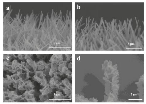
The typical morphology of CuO@CF and CuCoNi-oxide@CF electrodes were characterized by a field-emission scanning electron microscope (FESEM). A high coverage of Cu(OH)2 with pillar structure could be observed on the blue film grown from the copper foam, by immersing in an alkaline solution (Fig. 1a). Furthermore, it is found that CuO nanowire arrays derived from Cu(OH)2 pillars could be obtained by annealing at 200 ℃ for 2 h in air. The black film on the copper foam was indicative of the formation of CuO derived from thermal decomposition of Cu(OH)2 precursor. The length and diameter of the as-prepared CuO nanowires were estimated to be ~6 μm and ~200 nm (Fig. 1b), respectively. Furthermore, a high ratio of flower-like structure could be observed (Fig. 1c) after a simple hydrothermal process. After annealing process, a more compact flower-like structure CuCoNi-oxide could be obtained (Fig. 1d). The length and diameter of the as-prepared CuCoNi-oxidse with flower-like structure array were ~6 μm and ~500 nm, respectively. It is obvious that when Co and Ni elements were uniformly deposited onto CuO nanowires, the nanowires turned into more hyperbranched structure in comparison with pure CuO nanowires. This hyperbranched structure could provide more space for volumetric expansion, thus enhancing electrochemical stability of electrodes for LIBs. Apart from the peaks of Cu foam in the X-ray diffraction (XRD) of CuO nanowires, the diffraction peaks at 35.5°, 37.3°, 38.8° and 42.3° could be identified as CuO and Cu2O (Fig. S1a in Supporting information, red curve), respectively, which was ascribed to the CuO JCPDS No. 44-0706 and Cu2O JCPDS No. 34-1354. The diffraction peaks were obviously different from that of Cu(OH)2 nanowires, which was attributed to the formation of Cu(OH)2 JCPDS No. 35-0505 (Fig. S1a, black curve) [30]. Besides, the diffraction peaks located at 36.5°, 42.3° and 61.4° could be identified as the oxides of Co and Ni complex (Fig. S1b in Supporting information), derived from CuCoNi-oxide nanowire, which was ascribed to CoNiO2 JCPDS No. 10-0188. The above XRD analyses confirmed the formation of CuO nanowire and CuCoNi-oxide nanowire. It should be mentioned that Cu signals could be detected, owing to no impurities on Cu foam.

|
Download:
|
| Fig. 1. The SEM images of (a) Cu(OH)2 nanowires, (b) CuO nanowires, (c) CuCoNi ternary flower like structure and (d) annealed CuCoNi-oxide flower-like structure. | |
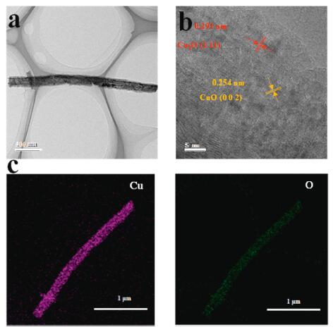
The typical TEM image of the CuO nanowire was shown in Fig. 2a. The length of the nanowire was estimated to be about 3 μm, in accordance with SEM results. The high-resolution transmission electron microscope (HRTEM) images also revealed the formation of CuO and Cu2O. In Fig. 2b, the lattice spacings of 0.291 and 0.254 nm were attributed to crystal plane (111) of Cu2O and crystal plane (002) of CuO, respectively [31]. Furthermore, the elemental mapping analysis (Fig. 2c) suggested that Cu and O elements were uniformly distributed in the nanowire structure. The TEM images of CuCoNi-oxide nanowire with a shell structure could be observed in Fig. 3a. The length of the nanowire was about 800 nm and the thickness of the shell was about 40 nm. The HRTEM images further verified the co-existence of CoCuOx and CoNiOx. The lattice spacings of 0.265 and 0.184 nm were associated with crystal plane (012) of CoCu2O3 and the crystal plane (220) of CoNiO2, respectively (Fig. S2 in Supporting information) [32]. Moreover, the elemental mapping analysis further confirmed the nanopillars was consisted with Cu and O elements, and the shell was consisted of Co, Ni and O elements. This indicated that Cu, Co, Ni and O in CuCoNi-oxide nanowires covered by shell were homogeneously distributed (Fig. 3b).

|
Download:
|
| Fig. 2. (a) TEM characterization of CuO nanowire; (b) HR-TEM image of CuO nanowire, and (c) elemental mapping images of the CuO nanowire. | |

|
Download:
|
| Fig. 3. (a) TEM characterization of CuCoNi-oxide nanowire and (b) elemental mapping images of the CuCoNi-oxide nanowire; XPS sepctra of (c) survey scan, (d) Co 2p high-resolution scan, and (e) Ni 2p narrow scan of CuCoNi-oxide nanowire. | |
The chemical composition and oxidation states of the samples (CuO and CuCoNi-oxide) were investigated by X-ray photoelectron spectroscopy (XPS). Note that the binding energies mentioned in this work was based on the reference peak of C 1s at 284.6 eV. Seen from the XPS survey scan in Fig. 3c, the presence of Cu, O and C elements was confirmed in both samples. In addition, the CuCoNi-oxide sample also suggested the co-existence of Co and Ni elements, indicating that Co and Ni were successfully doped into CuCoNi-oxide. It could be observed from Co 2p and Ni 2p high-resolution scan (Figs. 3d and e) that no signal was shown in the sample of CuO [33]. The difference in value between the peaks of Co 2p1/2 and Co 2p2/3 was 16.0 eV, indicating the existence of bivalent Co species in CuCoNi-oxide. For the Ni 2p XPS spectrum (Fig. 3e) of CuCoNi-oxide, four peaks located at 855, 861, 873 and 879 eV were presented, which could be assigned to Ni 2p3/2, Ni 2p3/2 satellite, Ni 2p1/2 and Ni 2p1/2 satellite signals of Ni2+, respectively. It indicated that before the ion exchange of Co2+, the bivalent Ni species was already doped into Cu(OH)2 during the hydrothermal process. Thus, on the basis of elemental mapping, XPS, XRD, SEM and TEM results, the CuCoNi-oxide nanowire was formed by doping Co2+ and Ni2+ dual-doped Cu(OH)2 array grown on CF. The well-defined array and flower-like morphology, electrically conductive copper foam and the multi-transition metal species, could guarantee CuO/CuCoNi-oxide nanowire a promising anode material for LIBs.
CuO nanowire structure grown from Cu substrate has been investigated as anode materials for LIBs, presenting high capacity and cyclability. Furthermore, some hierarchical architectures derived from nanostructured CuO film have been proposed and demonstrated to have excellent electrochemical performance [34]. In this study, the electrochemical behaviors of CuO and CuCoNi-oxide@CF electrodes were compared by cyclic voltammetry and galvanostatic discharge-charge measurements. The initial three discharge-charge curves of CuO and CuCoNi-oxide@CF were tested at a current density of 100 mA/g, as illustrated in Fig. 4. Two obvious potential plateaus located at about 1.4 V and 0.6 V could be observed from both CuO and CuCoNi-oxide@CF, corresponding to multistep of electrochemical reaction process. And the CV curves (Fig. S3 in Supporting informatoin) of CuO and CuCoNi-oxide nanowire LIBs also verified the two-peak electrochemical phenomenon of oxides. Furthermore, the initial discharge capacities of the CuO and CuCoNi-oxide nanowire electrodes were 1029 and 1191 mAh/g, respectively (Figs. 4a and b). The charge capacities of CuO and CuCoNi-oxide nanowire is about 685 and 1075 mAh/g, respectively. It should be mentioned that the first cycle Coulombic efficiencies of CuO and CuCoNi-oxide nanowire electrodes were determined to be 66.3% and 90.0%, respectively. The first cycle Coulombic efficiency was quite crucial for the design of full cell LIB. In order to avoid the irreversible lithium ions in the first cycle, it was recommended to conduct prelithiation treatment of anode materials using stabilized lithium metal powder for future practical applications [35, 36]. Also, the specific capacity values achieved in this work were higher than the theoretical capacity of 674 mAh/g, based on a maximum uptake of 2 mol of Li per mole of CuO. This phenomenon was common for metal oxide-based anode materials for electrochemical lithium storage [35]. The main cause for the large extra discharge capacity was due to the reversible formation of a solid electrolyte interface (SEI) film and polymeric gel-like film on the surface of the electrode materials, which was probably caused by electrochemical decomposition of electrolyte in the low potential region [37, 38].

|
Download:
|
| Fig. 4. Galvanostatic discharge-charge curve of (a) CuO nanowire and (b) CuCoNi-oxide. Rate performances of (c) CuO nanowire, and (d) CuCoNi-oxide nanowire. (e) Comparison of cycling performance comparison at a current density of 100 mA/g. (f) EIS results of CuO nanowire and CuCoNi-oxide nanowire electrodes before and after 10th cycles between CuO array electrode (black and blue hollow symbols) and CuCoNi-oxide array electrode (red and purple hollow symbols) at a current density of 100 mA/g, electric circuit model and some of frequencies (solid symbols). | |
Rate performance of CuO nanowire and CuCoNi-oxide nanowire electrodes were also investigated at various current density (Figs. 4c and d). Both specific capacity of CuO and CuCoNi-oxide electrodes showed good electrochemical stability at various current density. The CO electrodes endowed with hierarchical arrays exhibited good rate performance and high specific capacities even at high current density. The average specific capacity of CuO decreased from 685 mAh/g to 100 mAh/g, when the current density was increased from 100 mA/g to 2000 mA/g. When the current density was further decreased from 500 mA/g to 100 mA/g (Fig. 4c), the reversible capacity was again increased from 400 mAh/g to 550 mAh/g, suggesting that CuO electrode showed high specific capacity. Furthermore, the average specific capacity of CuCoNi-oxide declined from 1075 mAh/g to 145 mAh/g, when the current density was increased from 100 mA/g to 2000 mA/g. When the current density was declined from 500 mA/g to 100 mA/g (Fig. 4d), the reversible capacity again increased from 350 mAh/g to 760 mAh/g, implying that CuCoNi-oxide@CF electrode also exhibited better rate capacity. Such excellent rate performance might be attributed to the well-aligned arrays directly formed on the copper foam [39]. Further treatment turned the CuO array structure into a more hierarchical 3D, flower-like structure of CuCoNi-oxide. In addition, the CuCoNi-oxide anode also exhibited excellent performance in LIBs. Cycling performance of the CuO and CuCoNi-oxide array electrodes at a current density of 100 mA/g were presented in Fig. 4e. It could be observed that CuCoNi-oxide array electrode exhibited slow capacity fading and high capacity retention. Specifically, a capacity retention up to 73% at 100 mAh/g with a fading about 27% after 100 cycles was achieved with CuCoNi-oxide anode. Instead, the CuO array electrode (capacity retention up to 43% with a fading about 57%) after 100 cycles. Most of the copper-cobalt-nickel oxide nanowire arrays remained their flower-like structure and were closer to the substrate after long-term cycling (Fig. S4 in Supporting information). These results suggested that CuCoNi-oxide array electrodes exhibited excellent cycling stability and rate performance. In this work, the CuO and CuCoNi-oxide anodes not only facilitated the possibility of efficient transport of lithium ions, but also enhanced the diffusion of electrolyte into the inner region of the electrode and provide sufficient space to sustain the volume changes associated with lithium insertion and extraction, which could accelerate the electrochemical reaction kinetics and decrease polarization of the electrode during the discharge-charge cycle [40]. Furthermore, the electrochemical impedance spectra (EIS) of Li anode with CuCoNi-oxide and CuO after 10th cycles at 100 mA/g was compared with the pristine sample, as shown in Fig. 4f. Besides, the equivalent circuit model composed of an ohmic resistance (Rs), lithium ion charge transfer at interface (Rct and CPE) and Warburg impedance for solid state diffusion of lithium ions was proposed. A constant phase element (CPE) was used in the model instead of a pure capacitance, owing to the inhomogeneous surface. The results (Table S1 in Supporting information) suggested that charge-transfer resistance (Rct) at the Li- CuCoNi-oxide/CuO interface after 10th cycles (5.3 and 15.5 Ω, respectively) were much smaller than those of the pristine samples (7.5 and 24.7 Ω, respectively). This might be ascribed to the reaction of Cu2+/Co2+/Ni2+ with Li+, forming Li2O and Cu/Co/Ni and even further enhanced the formation and decomposition of SEI film [41], thus improving the surface affinity toward Li [42, 43]. Obviously, copper-cobalt-nickel oxide nanowire array anodes showed some advantages over other anodes, such as Si, Sn and graphite owing to the stable hierarchical structure and high specific capacity. Specifically, most of Si-based and Sn-based anode materials were fabricated in the form of powders and could suffer from relatively poor electron transport network [44-46]. Thus, copper-cobalt-nickel oxide nanowire arrays fully displayed discharge capacity, excellent cycling stability and enhanced rate performance could be obtained when CuO array was endowed with more hyperbranched CuCoNi-oxide structure.
In summary, a facile and efficient method was successfully explored for the fabrication of hierarchical CuO and CuCoNi-oxide nanowire arrays on Cu foam as free-standing anode materials for LIBs. The CuO/CuCoNi-oxide nanowire structure on Cu foam substrate was advantageous for realizing uniform and stable Li deposition and lowering the local current density. The fabrication process was simple and efficient. It not only showed good lithium affinity but also ensured fast electron transfer during the deposition process. By constructing hyperbranched nanowire structure, CuCoNi-oxide anodes exhibited better power density, cycle performance and cycling stability, compared to CuO with nanowire structure. This might be attributed to the unique hyperbranched structure of CuCoNi-oxide. which could accommodate more volumetric expansion space and provide more active sites, such as oxides of Co and Ni. Overall, this work demonstrated a facile and efficient method to fabricate a free-standing anodes with superior electrochemical performance for LIBs, which might be applicable to the fabrication of other metal oxide-based electrodes.
Declaration of competing interestThe work described was conducted entirely at our own laboratories and has not been published previously. The manuscript was approved by all authors and tacitly or explicitly by the responsible authorities where the work was carried out. If accepted, it will not be published elsewhere in the same form, in English or in any other language, without the written consent of the publisher. We have no finical competing interest.
AcknowledgmentsThis work is financially supported by the National Natural Science Foundation of China (No. 21975163) and China Postdoctoral Science Foundation (No. 2018M633125). The authors gratefully thank the research fellow, Wenguang Zhao, who helps conduct the TEM test and analysis in School of Advanced Materials, Peking University, Shenzhen Graduate School. The authors sincerely acknowledge the Instrumental Analysis center of Shenzhen University (Xili Campus) for HRTEM and SEM measurements and analysis. The authors also thank Dr. Bin Wang from City University of Hong Kong, who helped revise the manuscript and provided enlightening advice.
Appendix A. Supplementary dataSupplementary material related to this article can be found, in the online version, at doi:https://doi.org/10.1016/j.cclet.2020.06.013.
| [1] |
B. Dunn, H. Kamath, J.M. Tarascon, Science 334 (2011) 928-935. DOI:10.1126/science.1212741 |
| [2] |
D. Larcher, J.M. Tarascon, Nat. Chem. 7 (2015) 19-29. DOI:10.1038/nchem.2085 |
| [3] |
X.B. Cheng, R. Zhang, C.Z. Zhao, Q. Zhang, Chem. Rev. 117 (2017) 10403-10473. DOI:10.1021/acs.chemrev.7b00115 |
| [4] |
P.K. Nayak, L.T. Yang, W. Brehm, P. Adelhelm, Angew. Chem. Int. Ed. 57 (2018) 102-120. DOI:10.1002/anie.201703772 |
| [5] |
P.B. Geng, S.S. Zheng, H. Tang, et al., Adv. Energ. Mater. 8 (2018) 26. |
| [6] |
C.Z. Yuan, H.B. Wu, Y. Xie, X.W. Lou, Angew. Chem. Int. Ed. 53 (2014) 1488-1504. DOI:10.1002/anie.201303971 |
| [7] |
M. Chhowalla, H.S. Shin, G. Eda, et al., Nat. Chem. 5 (2013) 263-275. DOI:10.1038/nchem.1589 |
| [8] |
Q.Q. Ren, Z.B. Wang, K. Ke, S.W. Zhang, B.S. Yin, Ceram. Int. 43 (2017) 13710-13716. DOI:10.1016/j.ceramint.2017.07.083 |
| [9] |
X. Zuo, Y. Song, M. Zhen, Appl. Surf. Sci. 500 (2020) 144000. DOI:10.1016/j.apsusc.2019.144000 |
| [10] |
H. Yuan, L. Kong, T. Li, Q. Zhang, Chin. Chem. Lett. 28 (2017) 2180-2194. DOI:10.1016/j.cclet.2017.11.038 |
| [11] |
P. Poizot, S. Laruelle, S. Grugeon, L. Dupont, J.M. Tarascon, Nature 407 (2000) 496-499. DOI:10.1038/35035045 |
| [12] |
R.R. Salunkhe, Y.V. Kaneti, Y. Yamauchi, ACS Nano 11 (2017) 5293-5308. DOI:10.1021/acsnano.7b02796 |
| [13] |
Z. Hu, H. Liu, Ceram. Int. 41 (2015) 8257-8260. DOI:10.1016/j.ceramint.2015.03.010 |
| [14] |
J. Huang, M. Tan, J. Xu, et al., Appl. Surf. Sci. 488 (2019) 537-545. DOI:10.1016/j.apsusc.2019.05.223 |
| [15] |
J.C. Park, J. Kim, H. Kwon, H. Song, Adv. Mater. 21 (2009) 803-809. DOI:10.1002/adma.200800596 |
| [16] |
R. Dang, X. Jia, P. Wang, et al., Chin. Chem. Lett. 28 (2017) 2263-2268. DOI:10.1016/j.cclet.2017.09.064 |
| [17] |
S. Yuan, X.L. Huang, D.L. Ma, et al., Adv. Mater. 26 (2014) 2273-2279. DOI:10.1002/adma.201304469 |
| [18] |
G.D. Kang, Y.M. Cao, J. Membr. Sci. 463 (2014) 145-165. DOI:10.1016/j.memsci.2014.03.055 |
| [19] |
W.Q. Zhang, J.H. Nie, F. Li, Z.L. Wang, C.Q. Sun, Nano Energy 45 (2018) 413-419. DOI:10.1016/j.nanoen.2018.01.028 |
| [20] |
M.B. Zheng, H. Tang, L.L. Li, et al., Adv. Sci. 5 (2018) 24-31. |
| [21] |
H.J. Peng, J.Q. Huang, Q. Zhang, Chem. Soc. Rev. 46 (2017) 5237-5288. DOI:10.1039/C7CS00139H |
| [22] |
Y.H. Zhu, Y.B. Yin, X. Yang, et al., Angew. Chem. Int. Ed. 56 (2017) 7881-7885. DOI:10.1002/anie.201702711 |
| [23] |
R. Huang, Y. Li, Y. Song, L. Wang, J. Alloys. Compd. (2019) 152839. |
| [24] |
J.J. Mao, J. Iocozzia, J.Y. Huang, et al., Energ. Environ. Sci. 11 (2018) 772-799. DOI:10.1039/C7EE03031B |
| [25] |
G.Q. Tan, F. Wu, Y.F. Yuan, et al., Nat. Commun. 7 (2016) 10. |
| [26] |
R. Dang, X.L. Jia, X. Liu, et al., Nano Energy 33 (2017) 427-435. DOI:10.1016/j.nanoen.2017.01.024 |
| [27] |
S.R. Jia, Y. Wang, X.Q. Liu, et al., Nano Energy 59 (2019) 229-236. DOI:10.1016/j.nanoen.2019.01.081 |
| [28] |
S.L. Wu, Z.Y. Zhang, M.H. Lan, et al., Adv. Mater. 30 (2018) 7. |
| [29] |
J.X. Wang, Q.B. Zhang, X.H. Li, et al., Nano Energy 12 (2015) 437-446. DOI:10.1016/j.nanoen.2015.01.003 |
| [30] |
Z. Wang, F. Su, S. Madhavi, X.W. Lou, Nanoscale 3 (2011) 1618-1623. DOI:10.1039/c0nr00827c |
| [31] |
F.S. Ke, L. Huang, G.Z. Wei, et al., Electrochim. Acta 54 (2009) 5825-5829. DOI:10.1016/j.electacta.2009.05.038 |
| [32] |
H.H. Chen, J. He, Y.L. Li, et al., J. Mater. Chem. A 7 (2019) 7691-7700. DOI:10.1039/C9TA00275H |
| [33] |
Y. Zhang, T. Qu, F. Bi, et al., ACS Sustain. Chem. Eng. 6 (2018) 16859-16866. DOI:10.1021/acssuschemeng.8b04180 |
| [34] |
D.B. Zhang, Y. Shao, X.G. Kong, M.H. Jiang, X.D. Lei, Chem. Eng. J. 349 (2018) 491-499. DOI:10.1016/j.cej.2018.05.120 |
| [35] |
B. Wang, S. Wang, Y. Tang, et al., Appl. Energ. 252 (2019) 113452-113462. DOI:10.1016/j.apenergy.2019.113452 |
| [36] |
Z. Wang, Y. Fu, Z. Zhang, et al., J. Power Sources 260 (2014) 57-61. DOI:10.1016/j.jpowsour.2014.02.112 |
| [37] |
B. Wang, X.Y. Lu, Y. Tang, J. Mater. Chem. A 3 (2015) 9689-9699. DOI:10.1039/C5TA00140D |
| [38] |
L.Z. Xiong, Y. Teng, Y.X. Wu, J.J. Wang, Z.Q. He, Ceram. Int. 40 (2014) 15561-15568. DOI:10.1016/j.ceramint.2014.07.032 |
| [39] |
C.M. Zhang, J. Chen, Y. Zeng, et al., Nanoscale 4 (2012) 3718-3724. DOI:10.1039/c2nr30525a |
| [40] |
B. Ouyang, D.L. Chao, G.C. Jia, et al., Energy Storage Mater. 18 (2019) 462-469. DOI:10.1016/j.ensm.2018.08.007 |
| [41] |
L. Yanguang, T. Bing, W. Yiying, Nano Lett. 8 (2008) 265-270. DOI:10.1021/nl0725906 |
| [42] |
Z. Chen, L. Wei, G. Zhou, et al., Adv. Energ. Mater. 8 (2018) 1703404. DOI:10.1002/aenm.201703404 |
| [43] |
Y. Zhang, W. Zhang, M. Li, Z. Yang, Q. Wang, J. Mater. Chem. A 1 (2013) 14368-14374. DOI:10.1039/c3ta13018e |
| [44] |
H. Zhang, S. Liu, X. Yu, S.L. Chen, J. Alloys. Compd. 822 (2020) 153664-153671. DOI:10.1016/j.jallcom.2020.153664 |
| [45] |
G. Derrien, J. Hassoun, S. Panero, B. Scrosati, Adv. Mater. 19 (2007) 2336-2340. DOI:10.1002/adma.200700748 |
| [46] |
P. Poizot, S. Laruelle, S. Grugeon, L. Dupont, J.M. Tarascon, Nature 407 (2000) 496-499. DOI:10.1038/35035045 |