 2021, Vol. 32


b Laboratory of Clean Energy Chemistry and Materials, State Key Laboratory of Solid Lubrication, Lanzhou Institute of Chemical Physics, Chinese Academy of Sciences, Lanzhou 730000, China;
c Center of Materials Science and Optoelectronics Engineering, University of Chinese Academy of Sciences, Beijing 100080, China;
d School of Petrochemical Engineering, Lanzhou University of Technology, Lanzhou 730050, China;
e Dalian National Laboratory for Clean Energy, Dalian Institute of Chemical Physics, Chinese Academy of Sciences, Dalian 116000, China
The energy crisis and the greenhouse effect promote the rapid development of global new energy technologies [1]. Among various electrochemical energy storage systems, batteries and super-capacitors (SCs) are the most promising devices for portable electronic devices, electric vehicles and flexible wearable devices [2]. Lithium-ion batteries provide the highest energy density (150−200 Wh/kg), but at the expense of a limited cycle life [3]. On the other hand, while SCs benefit from the highest power capability (5−10 kW/kg) and long cycling life, their relatively lower energy densities (< 10 Wh/kg) hinder the practical application [4-6]. In order to obtain energy storage devices with excellent comprehensive performance, a new type of electrochemical energy storage device, metal ion hybrid SCs have been flourished successfully combining battery-type anode with capacitor-type cathode materials to achieve high energy density while keeping high power density [7, 8]. So far, lithium-ion hybrid SCs [9], sodium-ion hybrid SCs [10-13] and potassium-ion SCs [14-17] have been extensively studied, and great progress has been made with univalent Li+, Na+ and K+ as charge carriers, respectively [18-21]. However, the utilization of organic electrolytes has limited the application of these hybrid SCs due to the flammability, relatively low ionic conductivity and high viscosity [22-24]. In addition, the shortage of lithium resources and the complexity of the lithiation process have severely restricted the large-scale application of lithium-ion hybrid SCs [25-27]. Thus, researchers have been encouraged to look for relatively abundant cations as alternative. Some multivalent cations (Mg2+, Zn2+, Ni2+, Ca2+, Al3+, etc.) have been widely studied because one mole of reaction can provide several times more electrons than monovalent ions [28-32]. Among them, the aqueous zinc-ion hybrid super-capacitors (ZHSCs) holds great promise [33]. This is due to the inherent advantages of Zn metal such as eco-friendliness, abundant resource, high theoretical specific electric capacity (823 mAh/g), low redox potential of -0.76 V (vs. standard hydrogen electrode SHE) and stable chemistry in aqueous system [34]. Based on these advantages, Kang et al. assembled a new kind of ZHSC using zinc foil as anode, the activated carbon as cathode and 1 mol/L ZnSO4 as electrolyte, which achieved a high energy density of 84 Wh/kg and excellent cycle stability (a capacity retention of 91% over 10,000 cycles) [33]. In addition, Lu et al. demonstrated a high energy density (107.3 Wh/kg at a high current density of 4.2 A/g) and ultra-stable (99.7% retention after 20,000 cycles) aqueous ZHSC by introducing N-type dopants into a hierarchically porous carbon cathode to enhance its chemisorption of Zn2+ ions [35]. Despite these achievements, the cycling stability and the energy density of ZHSCs are still far from satisfactory. To improve the cycling performance, the porous carbon-based materials have been considered as cathode to assemble the ZHSCs, but the relatively low bulk density of carbon-based materials (generally 0.8 g/cm3) seriously affects the volumetric energy density of the device [36, 37]. Therefore, it remains a grand challenge to enhance the rate performance and cycle life of the Zn-based energy storage devices without sacrificing their remarkable volumetric energy storage characteristics [38, 39]. As far as we know, there is no relevant literature to study the volumetric properties of ZHSCs.
In this study, we demonstrated the ZHSC with high volumetric energy density and superb cycle stability employing the high-density porous carbon material as cathode and Zn foil directly used as anode in 1 mol/L ZnSO4 electrolyte. The dense three-dimensional (3D) graphene (DGH) possesses a specific surface area (SSA) of 208.29 m2/g and a high density of 1.50 g/cm3, which had a positive effect on increasing the volumetric energy density of the device. By the experiment, the ZHSC exhibited the high specific electric capacity of 222.03 F/g at a current density of 0.5 A/g, and the volumetric energy density of 118.42 Wh/L at a volumetric power density of 600.00 W/L, which was superior to those of the state-of-the-art carbon-based ZHSC. Furthermore, it showed excellent cyclic stability of 30,000 cycles at the current density of 10 A/g, and capacity retention rate of 80%. Due to the excellent electrochemical performance, DGH-based ZHSCs were expected to become the next generation of miniature energy storage devices.
The detailed preparation process of DGH electrode materials was as follows: Schematic diagram of the fabrication process for DGH was shown in Fig. S2a (Supporting information). Graphene oxide (GO) was prepared by the modified Hummers method using graphite powder as raw material [40]. Then the GO suspension at a concentration of 2 mg/mL (140 mg GO sheets into 70 mL deionized water) was transferred to a Teflon-lined autoclave for hydrothermal reaction (180 ℃ for 6 h) to prepare a black cylindrical graphene hydrogel. The cooled graphene hydrogel was rinsed repeatedly with deionized water and transferred to a vacuum oven for drying (40 ℃ for 72 h) to obtain DGH.
The configuration and mechanism of ZHSCs were schematically demonstrated in Fig. 1. For the ZHSC assembling, Zn foil was used as both anode and current collector. DGH coated on the stainless-steel current collector, the glass microfiber membrane and 1 mol/L ZnSO4 aqueous solution were used as the cathode, the separator and electrolyte, respectively. In the charging process (Fig. 1a), SO42– anions in the electrolyte migrated onto the surface of DGH which forming an electric double layer, as well as Zn2+ ions from the electrolyte were deposited onto the Zn foil. Reversibly, during the discharge process (Fig. 1b), SO42– anions diffused back into the electrolyte. Simultaneously, Zn2+ ions formed by the loss of electrons from Zn foil were also migrated back to the electrolyte. In the aqueous electrolyte, the rate of Zn2+ plating/stripping could be matched with the kinetic behavior of SO42– anions adsorption/desorption. Therefore, the aqueous ZHSC is feasible to achieve the excellent rate performance and high energy density. Fig. 1c exhibited the Ragone plot of ZHSC in this work compared with recently published energy storage devices [35, 41-43]. Our ZHSC demonstrated the maximum volumetric energy density (based on the cathode mass) of 118.42 Wh/L at a power density of 600.00 W/L and the power density of 24.00 kW/L with the volumetric energy density of 88.67 Wh/L, which was comparable to some standard electrochemical energy storage devices, such as nickel-metal hydride batteries [44, 45] and lithium sulfur batteries [46-48]. Moreover, the performance of ZHSC was superior to that of lead-acid batteries [49] and commercial SCs [7]. For achieving higher working voltage and specific electric capacity, individual units were connected in series and parallel for practical applications. For instance, two ZHSC coin cells in series behaved twice the electrochemical stability window relative to a single one (Fig. S1 in Supporting information), which can light characters "LZ", composed of thirty-three green light-emitting diodes (LEDs) (Fig. 1d). Meanwhile, two ZHSCs in a parallel configuration exhibited an enhanced specific electric capacity compared with that of a single one (Fig. S1).

|
Download:
|
| Fig. 1. Schematic illustration of the device construction and working mechanism of the ZHSC. (a) Charging process. (b) Discharging process. (c) Ragone plots of the ZHSC compared with the reported representative energy storage device. (d) Two ZHSCs in series lighted up characters "LZ". | |
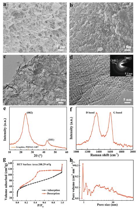
In order to explore the excellent electrochemical performance of ZHSC, the characteristics of cathode material was considered. The parameters of DGH were displayed in Fig. S2b (Supporting information). Compared with the sample before vacuum drying, the volume of DGH after drying was reduced by 80 times. According to the Eq. S1 (Supporting information), the density of DGH reached up to 1.50 g/cm3, which was higher than those of the reported carbon-based material [50-53]. The SEM image of 3D graphene hydrogel after hydrothermal treatment (Fig. 2a) displayed the 3D interconnected porous network structure composed of reduced graphene oxide (rGO) sheets. By comparison, Fig. 2b demonstrated the SEM image of DGH. It was shown that DGH was a dense structure. Although the DGH had highly dense structure, it still remains abundant pore structure. Further verification, the low magnification TEM image (Fig. 2c) of DGH showed that the rGO sheets were folded and intertwined into interconnected nanopores, indicating that the pore structure of the graphene hydrogel was maintained during the densification process. This stacking way facilitated the formation of a 3D frame, which ensured that the electrode material had an effective ion accessible surface area and a fast ion transport paths while being densified. Further morphology and structural characterization were performed by high resolution transmission electron microscopy (HRTEM) with selected area electron diffraction (SAED), as shown in Fig. 2d. The nanoscale pore structure of DGH was observed, which composed of curved graphene layers, which providing a smooth path for ion transfer. In addition, SAED pattern represented a polycrystalline ring pattern of DGH, which may be caused by the folding of the graphene sheets. The two diffraction rings corresponded to (002) and (101) crystal planes, indicating the graphitized properties of the rGO nanosheets.

|
Download:
|
| Fig. 2. Morphological and structure characterization of DGH. (a) SEM image of the obtained 3D graphene hydrogel by means of hydrothermal treatment. (b) SEM image. (c) TEM image. (d) High magnification TEM image. The insets showed the SAED pattern. (e) XRD pattern. (f) Raman spectrum. (g) N2 adsorption-desorption isotherms. (h) The pore size distribution curve. | |
The XRD pattern of DGH was showed in Fig. 2e. The diffraction peaks were detected at 24.2° and 43.0°, corresponding to the (002) and (101) crystal planes of graphite (JCPDS No. 41–1487), respectively. No impurity peaks appeared, which was consistent with SAED analysis. Raman spectrum of DGH demonstrated two strong characteristic peaks at around 1359 and 1603 cm–1, corresponding to the D band representing the disordered characteristic of the material and the G band reflecting the degree of graphitization, respectively (Fig. 2f). The intensity ratio of D band to G band was 0.996, verifying the stable carbon matrix of DGH. N2 adsorption-desorption isotherm and the corresponding pore size distribution of DGH were acquired. In Fig. 2g, the isotherm exhibited a hysteresis loop combining type I and type IV isotherms, indicating the presence of micropores and mesopores. In detail, the large amount of N2 adsorption at low relative pressures (< 0.1) demonstrated that DGH was rich in micropores. In the range of relative pressures from 0.4 to 0.8, the significant hysteresis characteristic illustrated the existence of mesoporous structures. As can be seen from the pore size distribution curve in Fig. 2h, the pores were mainly concentrated around 0.9 nm and 3.4 nm, reflecting the presence of smaller pores. The result further illustrated the higher density of DGH. Such a robust porosity endowed DGH with SSA of 208.29 m2/g and the specific pore volume of 0.21 cm3/g. The above result exhibited that DGH possessed a highly developed hierarchical porosity network of micropores in combination with the small amount of mesopores. Because of the relatively dense 3D interconnected porous network, DGH had the high electrical conductivity, which was 0.066 S/cm by using four-probe conductivity measurements superior to the reported carbon-based materials [54]. Moreover, the presence of mesopores promoted electrolyte ions to diffuse into the stacked graphene layers and remarkably increased the accessible surface area. Therefore, the rational combination of the high density and hierarchical porous structure, good graphitization degree and excellent conductivity made DGH as promising cathode for zinc-ion storage.
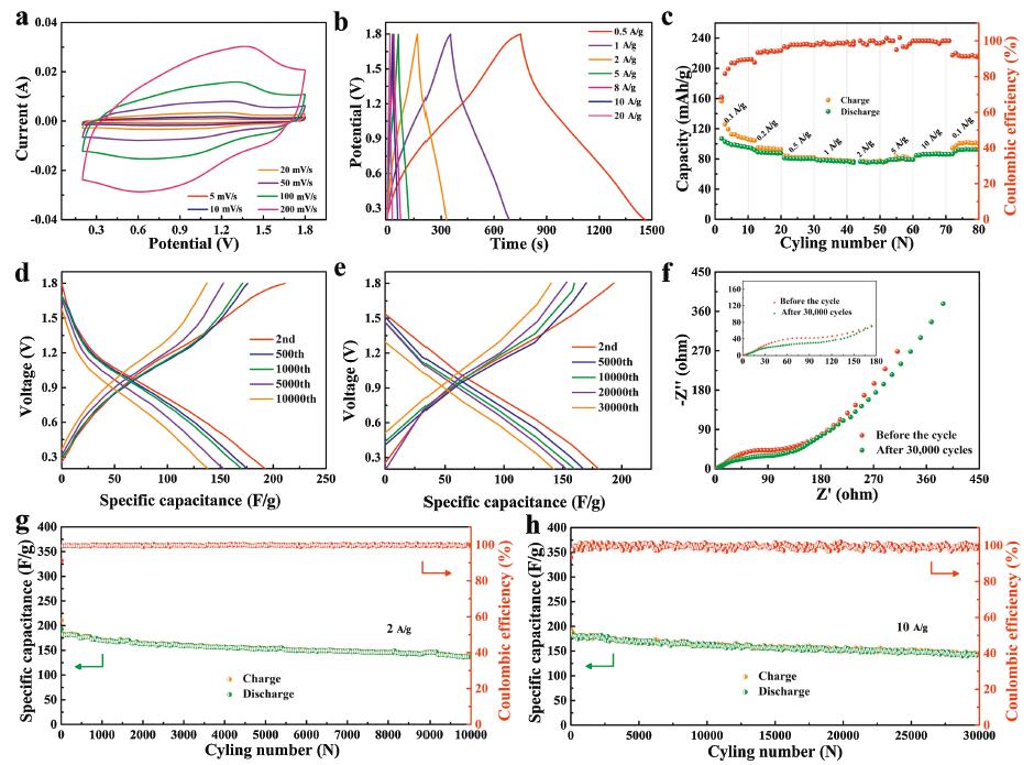
To evaluate electrochemical performance of DGH, the DGH-based ZHSC was assembled and tested in a 2032 coin-type cell using 1 mol/L ZnSO4 solution as electrolyte. As shown in the Fig. S3 (Supporting information), the CV and GCD curves presented the regular shapes in the range from 0.2 V to 1.8 V, suggesting the DGH-based ZHSC had a rechargeable and stable work voltage range of 0.2–1.8 V. In Fig. 3a, the CV curves were not obviously deformed even at the scan rate of 200 mV/s, indicating that ZHSC exhibited excellent reaction kinetics during rapid charging-discharging process. Fig. 3b showed the GCD plots of DGH-based ZHSC at different current densities. The good quasi-isosceles triangle shapes from 0.5 A/g to 20 A/g was demonstrated, suggesting a good reversibility during the charging-discharging processes. The calculation based on the discharge curves illustrated that the corresponding gravimetric specific electric capacity values Cg (the mass of DGH) were as high as 222.03 F/g at the current density of 0.5 A/g, and the corresponding volumetric specific electric capacity was 333.01 F/cm3. When increasing the current density to 20 A/g, the gravimetric specific electric capacity and volumetric specific electric capacity still remained 166.25 F/g and 249.38 F/cm3. The excellent performance may be attributed to the rich pore structure of the DGH cathode, which was extremely beneficial to the adsorption/desorption and diffusion of electrolyte ions during rapid charging-discharging process. For contrast, GO were used as cathode to construct the GO-based ZHSC and the electrochemical performance of GO-based ZHSC device was also investigated under the same conditions. As shown in Fig. S4 (Supporting information), compared with DGH-based ZHSC, the GO-based ZHSC presented the relatively low specific electric capacity of 126.69 F/g and 65.00 F/g at the current density of 0.5 A/g and 20 A/g, respectively. The specific electric capacity difference was mainly attributed to solvent-accessible surface area. Although GO possessed a well-ordered lamellar structure, the loss of active sites and the slow ions transport due to the stacking of sheets brought about the sharp decline in specific electric capacity. The above result indicated the fast and effective Zn2+ ions storage ability in DGH cathode. DGH possessed the larger effective SSA than that of GO, which provides more active sites for energy storage. Furthermore, the cycling performances of DGH-based ZHSC was evaluated in Fig. 3g. DGH-based ZHSC exhibited the striking cycling stability, in which the discharge specific electric capacity retained 72% of the initial discharge capacity (192.80 F/g) after 10,000 charge-discharge cycles at a current density of 2 A/g. Remarkably, it still held an impressively discharge specific electric capacity of 142.90 F/g even at a high current density of 10 A/g, and remain the capacity retention of 80% when the cycling was extended to a long duration of 30,000 cycles, as shown in Fig. 3h. In addition, the coulombic efficiency maintained almost 100% during the cycling term.

|
Download:
|
| Fig. 3. Characterization of electrochemical properties of DGH-based ZHSC. (a) CV curves at scan rates from 5 mV/s to 200 mV/s. (b) GCD curves at different current densities from 0.5 A/g to 20 A/g. (c) The rate performances. (d) GCD curves at different cycles at a current density of 2 A/g. (e) GCD curves at different cycles at a current density of 10 A/g. (f) Nyquist diagram of DGH-based ZHSC before and after 30,000 cycles at current density of 10 A/g. (g, h) long-term cycling stability at the current density of 2 A/g for 10,000 cycles and 10 A/g for 30,000 cycles, respectively. | |
To further authenticate the cycling stability of ZHSC, the typical charge-discharge profiles of DGH-based ZHSC ranging from 2nd cycle to 30,000th at current densities of 2 A/g and 10 A/g were shown in Figs. 3d and e, respectively. It was observed that the discharge curves had a slight displacement, indicating its high cycle stability. It was concerned with the rich pore structure of DGH, which was extremely beneficial to the diffusion of electrolyte ions during rapid charging-discharging process. Furthermore, the rate capability of DGH-based ZHSC was evaluated in detailed at various current densities. ZHSC was firstly cycled at 0.1 A/g for 10 cycles, followed by cycling with a stepwise increase of the charging-discharging rates to 10 A/g (Fig. 3c). DGH-based ZHSC exhibited an excellent capacity retention ratio of 80.4% indicating that the DGH-based ZHSC possessed a superior rate performance. When the current density went back to 0.1 A/g, the capacity can be resumed to the original capacity, further illuminating the excellent cycle stability.
By contrast, the cycle performance of GO-based ZHSC appeared a short cycle life (Fig. S4e), especially at a high current density of 10 A/g. To gain insight into the electrolyte ions transport and kinetics behaviors of hierarchical porous structure of DHG, EISs of GO-based ZHSC and DGH-based ZHSC were measured at the open circuit voltage in the frequency range of 0.01 Hz to 100 MHz, as shown in Fig. S4c. It was observed that DGH cathode exhibited the smaller ohmic resistance (Rs) and charge transfer resistance (Rct) than those of GO cathode, clarifying that the combination of high electric conductivity and interconnected hierarchically porous structure of DGH cathode facilitated the rapid Zn2+ diffusion, which can remarkably improve its rate performances. Moreover, the EISs measurement of DGH-based ZHSC were employed before and after 30,000 cycles at a current density of 10 A/g (Fig. 3f). It can be found that the equivalent series impedance after cycling did not increase significantly, while the charge transfer impedance and diffusion impedance slightly increase, which indicating that DGH had good conductivity and structural stability even after a long-term cycling, but the impedance transformation of the device was also related to the anode.
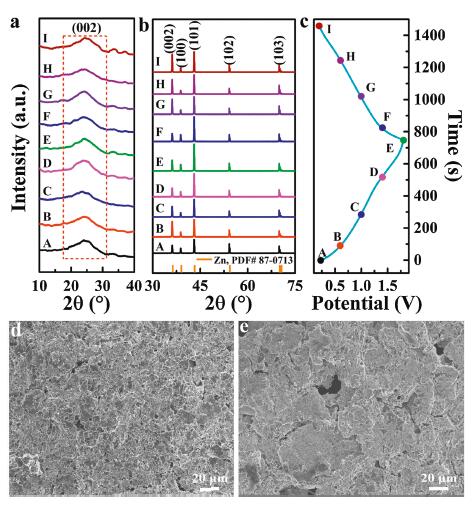
Subsequently, the ex-situ XRD patterns of different charge-discharge voltages in the first cycle were used to explore the energy storage mechanism of DGH cathode and Zn foil anode in ZHSC, as shown in Fig. 4. The GCD curves of DGH-based ZHSC started from 0.2 V, then charged to 1.8 V, and finally discharged to 0.2 V again, as shown in Fig. 4c. Here, 9 points from A to I were selected as detection targets, corresponding to 0.2, 0.6, 1.0, 1.4 and 1.8 V, respectively. Fig. 4a showed the XRD patterns of DGH cathode under different charge-discharge voltages. It was observed that the corresponding (002) crystal plane located at 24.1° did not show no significant change, illustrating the physical adsorption-desorption process occurred on the surface of DGH cathode. Meanwhile, SEM images of DGH cathode before and after cycling test were shown in Figs. 4d and e. After cyclic testing, the morphology had made little visible difference. All the results implied that DGH maintained a stable structure under different charge-discharge voltages. The structural transformation of Zn anode was analyzed by XRD and SEM measurements. Fig. 4b showed the XRD patterns of Zn anode under different charge-discharge voltages. All the Zn (JCPDS No. 87–0713) anode exhibited mainly five characteristic peaks of (002), (100), (101), (102) and (103) corresponding to 2θ=36.1°, 38.8°, 43.0°, 54.2° and 70.1°, respectively. With the progress of the charging process, the intensities of peaks of (100) and (101) gradually increased, representing that Zn2+ ions were deposited on the surface of Zn anode. Inversely, when the discharging process continued, the intensity of (100) and (101) diffraction peaks gradually weakened, suggesting the stripping transformation of metallic Zn. The results displayed the changed crystal orientation of metallic Zn in surface region. During the charging-discharging process, no characteristic peaks of impurities, such as forms of ZnO, were observed within the detection sensitivity, manifesting the good reversible zinc plating/stripping capability. Based on the above analysis, the energy storage mechanism for DGH-based ZHSC system was dominated by ions adsorption/desorption on DGH cathode and Zn2+ plating/stripping on Zn anode.

|
Download:
|
| Fig. 4. Mechanism study of ZHSC. (a) Ex-situ XRD patterns of DGH cathode. (b) Ex-situ XRD patterns of Zn anode. (c) The first GCD curve of DGH at current density of 1 A/g. (d, e) SEM images of DGH electrode before and after 30,000 cycles at current density of 10 A/g, respectively. | |
To better understand the potential cause of the capacity slightly decay and the impedance enhancement of DGH-based ZHSC after the cycle, electrode reactions occurred on Zn anode were further investigated. Fig. S6a (Supporting information) showed the optical images of Zn foil before and after charge-discharge 30,000 cycles at current density of 10 A/g. Compared to the original Zn foil, Zn foil after the cycle exhibited rough surface, which was attributed to the deposited Zn on the surface of Zn foil anode. The phenomenon further suggested that Zn2+ plating/stripping was the primary reaction on Zn anode. Furthermore, in comparison with XRD patterns before and after 30,000 cycles, the Zn4(OH)6SO4·5H2O (JCPDS No. 39–0688) was detected on the surface of the Zn foil after the cycled. Notably, in the first charging-discharging cycle, the characteristic peaks of Zn4(OH)6SO4·5H2O were not observed. The possible reason was that the very low content failed to reach the detection sensitivity of XRD measurement. Following the increase of the charging-discharging cycles, the peak intensity of Zn4(OH)6SO4·5H2O in XRD patterns was reflected. The SEM image displayed the flake-like morphology of Zn4(OH)6SO4·5H2O. The researches had been reported that Zn4(OH)6SO4·5H2O products form in ZnSO4 aqueous solution, following the reaction equation:

|
(1) |
Due to the precipitation of Zn4(OH)6SO4·5H2O, the ion transmission was impeded, resulting in a slight increase in charge transfer resistance and diffusion resistance after the cycles.
In summary, an aqueous ZHSC with high volumetric energy density and excellent cycle stability was assembled using the prepared DGH as a cathode. Because DGH with high density and porous structure facilitates the fast transfer of ions/electrons and ensures sufficient charge storage sites, DGH-based ZHSC exhibits an extremely high volumetric energy density of 118.42 Wh/L, a superb power density of 24.00 kW/L, as well as the ultralong cycle stability (80% capacity retention after 30,000 cycles), which was much better than most recently reported advanced ZHSCs. More importantly, this work opens up the possibility of dense materials being used as electrode materials of ZHSC, promotes the development of novel portable ZHSC energy devices with superior comprehensive performances.
Declaration of competing interestNo conflict of interest exits in the submission of this manuscript, and manuscript is approved by all authors for publication.
AcknowledgmentsThis work was supported by the National Nature Science Foundations of China (No. 21965019), the China Postdoctoral Science Foundation (No. 2017M613248), the Natural Science Foundation of Gansu Province (No. 1506RJZA091) andt he Scientific Research Foundation of the Higher Education Institutions of Gansu Province (No. 2015A-037).
Appendix A. Supplementary dataSupplementary material related to this article can be found, in the online version, at doi:https://doi.org/10.1016/j.cclet.2020.06.037.
| [1] |
J.B. Goodenough, Energy Environ. Sci. 7 (2014) 14-18. DOI:10.1039/C3EE42613K |
| [2] |
L. Liu, Q. Dou, Y. Sun, et al., J. Mater. Chem. A 7 (2019) 20398-20404. DOI:10.1039/C9TA07209H |
| [3] |
Z. Jian, W. Wang, M. Wang, et al., Chin. Chem. Lett. 29 (2018) 1768-1772. DOI:10.1016/j.cclet.2018.11.002 |
| [4] |
S. Zhang, N. Pan, Adv. Energy Mater. 5 (2015) 1401401. DOI:10.1002/aenm.201401401 |
| [5] |
M. Salanne, B. Rotenberg, K. Naoi, et al., Nat. Energy 1 (2016) 16070. DOI:10.1038/nenergy.2016.70 |
| [6] |
J. Yan, Q. Wang, T. Wei, Z. Fan, Adv. Energy Mater. 4 (2014) 1300816. DOI:10.1002/aenm.201300816 |
| [7] |
P. Simon, Y. Gogotsi, World Scientific (2020) 320-329. |
| [8] |
J. Jiang, P. Nie, S. Fang, et al., Chin. Chem. Lett. 29 (2018) 624-628. DOI:10.1016/j.cclet.2018.01.029 |
| [9] |
B. Li, J. Zheng, H. Zhang, et al., Adv. Mater. 30 (2018) 1705670. DOI:10.1002/adma.201705670 |
| [10] |
H. Wang, C. Zhu, D. Chao, Q. Yan, H.J. Fan, Adv. Mater. 29 (2017) 1702093. DOI:10.1002/adma.201702093 |
| [11] |
P. Wang, B. Yang, G. Zhang, et al., Chem. Eng. J. 353 (2018) 453-459. DOI:10.1016/j.cej.2018.07.150 |
| [12] |
J. Ding, H. Wang, Z. Li, et al., Energy Environ. Sci. 8 (2015) 941-955. DOI:10.1039/C4EE02986K |
| [13] |
Z. Zhang, M. Li, Y. Gao, et al., Adv. Funct. Mater. 28 (2018) 1802684. DOI:10.1002/adfm.201802684 |
| [14] |
S. Dong, Z. Li, Z. Xing, et al., ACS Appl. Mater. Interfaces 10 (2018) 15542-15547. DOI:10.1021/acsami.7b15314 |
| [15] |
L. Fan, K. Lin, J. Wang, R. Ma, B. Lu, Adv. Mater. 30 (2018) 1800804. DOI:10.1002/adma.201800804 |
| [16] |
A. Le Comte, Y. Reynier, C. Vincens, C. Leys, P. Azaïs, J. Power Sources 363 (2017) 34-43. DOI:10.1016/j.jpowsour.2017.07.005 |
| [17] |
N. Wu, W. Yao, X. Song, et al., Adv. Energy Mater. 9 (2019) 1803865. DOI:10.1002/aenm.201803865 |
| [18] |
Y. Ma, H. Chang, M. Zhang, Y. Chen, Adv. Mater. 27 (2015) 5296-5308. DOI:10.1002/adma.201501622 |
| [19] |
L. Shen, L. Yu, X.Y. Yu, X. Zhang, X.W. Lou, Angew. Chem. 54 (2015) 1868-1872. DOI:10.1002/anie.201409776 |
| [20] |
E. Lim, C. Jo, M.S. Kim, et al., Adv. Funct. Mater. 26 (2016) 3711-3719. DOI:10.1002/adfm.201505548 |
| [21] |
S. Komaba, T. Hasegawa, M. Dahbi, K. Kubota, Electrochem. commun. 60 (2015) 172-175. DOI:10.1016/j.elecom.2015.09.002 |
| [22] |
R. Malik, Joule 1 (2017) 17-19. DOI:10.1016/j.joule.2017.08.016 |
| [23] |
A. Eftekhari, Adv. Energy Mater. 8 (2018) 1801156. DOI:10.1002/aenm.201801156 |
| [24] |
J. Guo, Y. Ma, K. Zhao, et al., ChemElectroChem 6 (2019) 5433-5438. DOI:10.1002/celc.201901591 |
| [25] |
J. Zhang, Z. Shi, C. Wang, Electrochim. Acta 125 (2014) 22-28. DOI:10.1016/j.electacta.2014.01.040 |
| [26] |
X. Sun, X. Zhang, H. Zhang, et al., J. Power Sources 270 (2014) 318-325. DOI:10.1016/j.jpowsour.2014.07.146 |
| [27] |
J. Zhang, J. Wang, Z. Shi, Z. Xu, Chin. Chem. Lett. 29 (2018) 620-623. DOI:10.1016/j.cclet.2018.01.031 |
| [28] |
R. Schwarz, M. Pejic, P. Fischer, et al., Angew. Chem. 55 (2016) 14958-14962. DOI:10.1002/anie.201606448 |
| [29] |
D. Kundu, B.D. Adams, V. Duffort, S.H. Vajargah, L.F. Nazar, Nat. Energy 1 (2016) 1-8. |
| [30] |
J. Li, E. Shangguan, D. Guo, et al., J. Power Sources 270 (2014) 121-130. DOI:10.1016/j.jpowsour.2014.07.098 |
| [31] |
A. Ponrouch, C. Frontera, F. Bardé, M.R. Palacín, Nat. Mater. 15 (2016) 169-172. DOI:10.1038/nmat4462 |
| [32] |
E. Zhang, W. Cao, B. Wang, et al., Energy Storage Mater. 11 (2018) 91-99. DOI:10.1016/j.ensm.2017.10.001 |
| [33] |
L. Dong, X. Ma, Y. Li, et al., Energy Storage Mater. 13 (2018) 96-102. DOI:10.1016/j.ensm.2018.01.003 |
| [34] |
B. Li, J. Quan, A. Loh, et al., Nano Lett. 17 (2017) 156-163. DOI:10.1021/acs.nanolett.6b03691 |
| [35] |
H. Zhang, Q. Liu, Y. Fang, et al., Adv. Mater. 31 (2019) 1904948. DOI:10.1002/adma.201904948 |
| [36] |
Y. Gogotsi, P. Simon, Sci. 334 (2011) 917. DOI:10.1126/science.1213003 |
| [37] |
Y. Tao, X. Xie, W. Lv, et al., Sci. Rep. 3 (2013) 2975. DOI:10.1038/srep02975 |
| [38] |
P. Zhang, Y. Li, G. Wang, et al., Adv. Mater. 31 (2019) 1806005. DOI:10.1002/adma.201806005 |
| [39] |
G. Sun, H. Yang, G. Zhang, et al., Energy Environ. Sci. 11 (2018) 3367-3374. DOI:10.1039/C8EE02567C |
| [40] |
W. Lv, D. Tang, Y. He, et al., ACS Nano 3 (2009) 3730-3736. DOI:10.1021/nn900933u |
| [41] |
H. Wang, M. Wang, Y. Tang, Energy Storage Mater. 13 (2018) 1-7. DOI:10.1016/j.ensm.2017.12.022 |
| [42] |
H. Zhou, C. Liu, J. Wu, et al., J. Mater. Chem. A 7 (2019) 9708-9715. DOI:10.1039/C9TA01256G |
| [43] |
J. Han, K. Wang, W. Liu, et al., Nanoscale 10 (2018) 13083-13091. DOI:10.1039/C8NR03889A |
| [44] |
Z. Weng, F. Li, D.W. Wang, L. Wen, H.M. Cheng, Angew. Chem. 52 (2013) 3722-3725. DOI:10.1002/anie.201209259 |
| [45] |
A. Burke, M. Miller, J. Power Sources 196 (2011) 514-522. DOI:10.1016/j.jpowsour.2010.06.092 |
| [46] |
H. Li, Y. Tao, C. Zhang, et al., Adv. Energy Mater. 8 (2018) 1703438. DOI:10.1002/aenm.201703438 |
| [47] |
Q. Pang, X. Liang, C.Y. Kwok, J. Kulisch, L.F. Nazar, Adv. Energy Mater. 7 (2017) 1601630. DOI:10.1002/aenm.201601630 |
| [48] |
W. Xue, L. Miao, L. Qie, et al., Curr. Opin. Electrochem. 6 (2017) 92-99. DOI:10.1016/j.coelec.2017.10.007 |
| [49] |
T. Lin, I.W. Chen, F. Liu, et al., Sci. 350 (2015) 1508-1513. DOI:10.1126/science.aab3798 |
| [50] |
J. Yan, Q. Wang, C. Lin, T. Wei, Z. Fan, Adv. Energy Mater. 4 (2014) 1400500. DOI:10.1002/aenm.201400500 |
| [51] |
J. Hu, Z. Kang, F. Li, X. Huang, Carbon 67 (2014) 221-229. DOI:10.1016/j.carbon.2013.09.085 |
| [52] |
J. Hu, H. Wang, Q. Gao, H. Guo, Carbon 48 (2010) 3599-3606. DOI:10.1016/j.carbon.2010.06.008 |
| [53] |
Y. Yoon, K. Lee, S. Kwon, et al., ACS Nano 8 (2014) 4580-4590. DOI:10.1021/nn500150j |
| [54] |
C. Zhao, Y. Shi, J. Xie, F. Lei, L. Zhang, Mater. Res. Exp. 6 (2019) 095526. DOI:10.1088/2053-1591/ab326e |