 2021, Vol. 32


b School of Materials Science and Engineering, Chang'an University, Xi'an 710064, China
Lithium-ion batteries (LIBs) currently are the major power source for electric vehicles and portable electronics [1-3]. With the traditional graphite anode approaching its theoretical capacity limit (372 mAh/g for LiC6), the development of higher capacity anodes is urgently requisite to meet the ever-increasing energy density requirement for next-generation LIBs [4-6]. Among them, silicon is regarded as the promising anode candidate because of its high theoretical capacity (3579 mAh/g for Li15Si4) and appropriate operating voltage (~0.4 V vs. Li/Li+) [7, 8]. Nevertheless, the huge volume variations (~300%) during discharge/charge processes result in electrode pulverization and uncontrollable solid-electrolyte interphase (SEI) layer growth, thus leading to severe capacity decay and low Coulombic efficiency, which block the practical applications of high-capacity silicon anode [9-11].
To address these issues, various Si nanocomposites have been extensively studied, such as nano-Si/carbon composites [12, 13]. The high fracture toughness of nano-Si can withstand the large volume changes without breaking, and the conductive carbon can significantly improve the electrical conductivity of nano-Si based electrodes [12, 14-16]. Among them, the nano-Si/graphite composites anodes are considered to be the most promising due to their relatively high capacities, low volume variations and high initial Coulombic efficiency (ICE) [17-20]. Noteworthy, the composites of nano-Si and graphite are commonly prepared through physical mechanical blending and milling [21, 22]. However, considering the tremendous volume change of nano-Si during repeated cycling, the nano-Si tends to detach from the graphite substrate owing to the dynamical interface during electrochemical processes combined with the inherently weak adhesion between Si and sp2 carbon layers, which would render the destruction of interfacial electron transfer network [23-25]. This leads to the loss of active silicon and thus poor cycling stability.
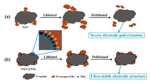
Herein, we design and prepare a robust and stable interface between nano-Si and graphite enabled by the interfacial covalent bonds. Abundant Si-Ti and Ti-C bonds are induced through high temperature treatment. They act as the robust bridge to bond nano-Si and graphite anodes, leading to the greatly improved adhesion force between them. The nano-Si stays firmly on the graphite surface during electrochemical cycling processes without obvious detachment, resulting in the enormously enhanced structural integrity and electrical connectivity (Fig. 1). Moreover, the common agglomeration problem of nano-Si is also effectively alleviated owing to the strong interfacial adhesion between nano-Si and graphite. Consequently, the as-obtained anodes (Si@C@TiO2) exhibit a good capacity retention of 90.0% after 420 cycles at 0.5 C and a high ICE of 90.2%.

|
Download:
|
| Fig. 1. Schematic illustration of the stabilization mechanism of Si@C@TiO2 electrode with the assistance of SiTi and TiC covalent bonds during cycling. (a) Si@C electrode and (b) Si@C@TiO2 electrode. The abundant SiTi and TiC bonds formed between nano-Si and graphite greatly enhance the interfacial adhesion force, accommodating the huge volume changes of nano-Si during battery cycling, thus resulting in integrated and stabilized electrode structure without obvious detachment. | |
The synthetic process of nano-Si/graphite nanocomposite (Si@C@TiO2) was schematically illustrated in Fig. S1 (Supporting information). First, the nano-sized Si particles were prepared by a facile high-energy ball-milling technology. Then, the Si nanoparticles and graphite were slowly added to the MXene (Ti3C2Tx) aqueous solution, and further sonicated to obtain the homogeneous dispersion. Note that the MXene aqueous solution was acquired by etching the MAX (Ti3AlC2) precursor according to the previous study [26]. After that, the Si@C@MXene composite was fabricated by the spray drying method. Finally, the Si@C@TiO2 nanocomposite was collected after the heat treatment of Si@C@MXene precursor in a reducing atmosphere, to form Si-Ti and Ti-C covalent bonds between Si nanoparticles and graphite. For comparison, the Si@C composite was also prepared by the basically similar process without the addition of MXene (Fig. S1 in Supporting information).
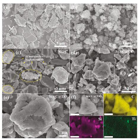
The microstructure of the raw materials and nanocomposites is investigated by scanning electron microscopy (SEM) as revealed in Fig. 2. Fig. 2a shows the graphite particle has a broad size distribution (5−10 μm) with a relatively smooth surface. Fig. 2b demonstrates most of the Si particles are nano-sized and only a few micro-sized particles can be observed. It needs to be emphasized that the nanoscale particle-size is essential to maintain the structural integrity of silicon anodes because of its greatly improved fracture toughness [16]. Figs. 2d and e show the Si@C@TiO2 nanocomposites have a basically similar size distribution to the pristine graphite particles, which is favorable for industrial applications due to the improved processability of electrode materials [27]. Importantly, nearly no exposed Si nanoparticles on the graphite surface can be observed (Figs. 2d and e), indicating the intimate and stable interfacial adhesion between them. Conversely, several Si nanoparticles agglomerations are clearly found outside the graphite particles as shown in Fig. 2c and Fig. S2 (Supporting information). This phenomenon is mainly attributed to the high surface energy of nano-Si and the weak adhesion between Si and graphite. Moreover, as shown in Fig. 2f, the energy-dispersive X-ray element mappings further testify the uniform and tight adhesion of Si nanoparticles on graphite microparticles. We also note that element Ti is evenly decorated on graphite surface (Fig. 2f), promising for forming more Si-Ti and Ti-C covalent bonds.

|
Download:
|
| Fig. 2. Microstructure of the raw materials and nanocomposites. (a) SEM image of graphite. (b) SEM image of Si nanoparticles. (c) SEM image of Si@C nanocomposites. (d-f) SEM images of Si@C@TiO2 nanocomposites. (e) The magnified image of the white box in (d). (f) The energy-dispersive X-ray element mappings, the scale bar is 2 μm. | |
Fig. S3a (Supporting information) shows the X-ray diffraction (XRD) patterns of the as-obtained samples. The sharp diffraction peaks located at 28.4°, 47.3°, 56.0° and 69.2° are in good agreement with the crystal planes of Si (111), (220), (311), (400) [28]. Interestingly, the peaks belong to crystal Si in Si@C@TiO2 nanocomposites are much higher than bare Si nanoparticles, indicating the improved crystallinity of Si nanoparticles, and the high crystallinity promises for high ICE. The high crystallinity may be ascribed to that the high temperature treatment process (1000 ℃) eliminates some of surface and structural defects of Si nanoparticles [29]. The two diffraction peaks at 21.5° and 35.7° can be assigned to crystal TiO2 [30]. Also, we observe that a new peak appears at 456.5 eV in Si@C@TiO2 nanocomposites compared with Si@C sample (Fig. S3b in Supporting information), which can be attributed to Ti 2p [31]. The mass content of titanium element in Si@C@TiO2 nanocomposites is calculated to be 2.75% based on the XPS data (Table S1 in Supporting information). These two phenomena together confirm the successful introduction of TiO2. The other diffraction peaks in XRD patterns are ascribed to graphite [18], consistent with the SEM results (Fig. 2).
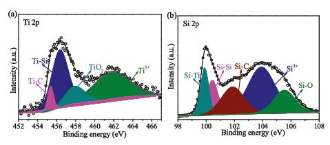
The chemical states and compositions of Si@C@TiO2 nanocomposites are further investigated by XPS as revealed in Fig. 3. The high-resolution Ti 2p spectrum of Si@C@TiO2 nanocomposites (Fig. 3a) can be resolved as the sum of Ti-C (455.4 eV), Ti-Si (456.4 eV), TiO2 (458.0 eV) and Ti3+ (461.9 eV) [31-34]. The apparent peak located at 461.9 eV confirms the formation of Ti3+ caused by hydrogenation of TiO2 at high temperature (1000 ℃) and reduced atmosphere [35]. It should be stressed that the introduction of Ti3+ contributes to improving the electrical conductivity of Si@C@TiO2 nanocomposites because of the decreased band gap of TiO2 [30]. The high-resolution Si 2p spectrum of Si@C@TiO2 nanocomposites (Fig. 3b) can be deconvoluted into five peaks at 99.9, 100.4, 101.9, 103.9 and 105.5 eV, corresponding to Ti-Si, Si-Si, Si-C, Si3+ and Si-O, respectively [32, 36, 37]. The two peaks located at 456.4 eV (Ti 2p) and 99.9 eV (Si 2p) together indicate the formation of Ti-Si bonds, the sharp peak located at 455.4 eV (Ti 2p) confirms the formation of Ti-C bond. These two factors imply the successful introduction of covalent bonds between nano-Si and graphite after high temperature treatment, which is crucial to the structural stability and integrity of Si@C@TiO2 nanocomposites.

|
Download:
|
| Fig. 3. High-resolution XPS spectra of Si@C@TiO2 nanocomposites. (a) Ti 2p. (b) Si 2p. | |
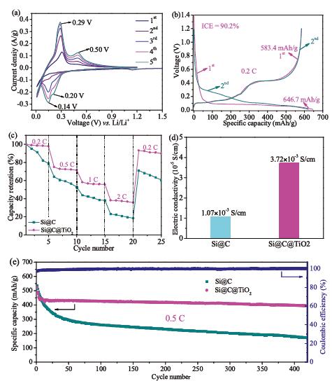
The electrochemical reaction of Si@C@TiO2 electrode is initially investigated by cyclic voltammetry (CV) between 0.01 V and 1.2 V versus Li/Li+ at a scan rate 0.1 mV/s. As shown in Fig. 4a, the small cathodic peak at 1.14 V in the initial discharge process is related to the electrolyte decomposition and SEI formation on the electrode surface [38]. The other two cathodic peaks at 0.2 V and 0.14 V are ascribed to the lithiation process to form Li-Si alloy and LixC6 (0≤x≤1) [18]. The apparent anodic peaks at 0.5 V and 0.29 V are related to the delithiation process from Li-Si alloy and LixC6 to amorphous Si and C [17]. We observe that both the anodic and cathodic peaks become more evident during the initial five CV cycles, implying the existence of electrochemical activation process [39, 40]. Fig. 4b shows the initial two cycles galvanostatic charge/discharge curves of Si@C@TiO2 electrode in the voltage of 0.01–1.2 V versus Li/Li+ at 0.2 C (1 C=700 mA/g). The initial discharge and charge capacities of Si@C@TiO2 electrode are 646.7 mAh/g and 583.4 mAh/g, corresponding the ICE of 90.2%, which is higher than Si@C electrode (87.3%) (Fig. S4 in Supporting information) because of the integrated and stabilized electrode structure with the help of Si-Ti and Ti-C covalent bonds. Furthermore, the rate performance of Si@C@TiO2 electrode is evaluated at various current densities from 0.2 C to 2 C as revealed in Fig. S5 (Supporting information), the reversible charge capacities are 604.8 mAh/g, 440.4 mAh/g, 338.8 mAh/g and 233.5 mAh/g at the current densities of 0.2 C, 0.5 C, 1 C and 2 C, respectively. Furthermore, we observe that the Si@C@TiO2 electrode delivers more higher capacity retention that of Si@C electrode at each current density (Fig. 4c), illustrating its good reaction kinetics mainly due to the greatly improved electrical conductivity (Fig. 4d). The four-probe measurement exhibits the electrical conductivity of Si@C@TiO2 electrode is about three times higher that of Si@C electrode caused by the Ti3+ (Figs. 4d and 3a). Moreover, the cycling performance of Si@C@TiO2 electrode and Si@C electrode are evaluated at a current density of 0.5 C as shown in Fig. 4e. The reversible capacities are 393.8 mAh/g and 170.1 mAh/g for Si@C@TiO2 electrode and Si@C electrode after 420 cycles and the corresponding capacity retentions are 90.0% and 40.5% (compared with the 10th cycle). For comparison, the cycling performance of Si@C@MXene electrode is also evaluated (Fig. S6 in Supporting information), the reversible capacity is 261.9 mAh/g after 250 cycles at 0.5 C and the capacity retention is 62.1% (compared with the 10th cycle). The average Coulombic efficiency of Si@C@TiO2 electrode is as high as 99.5%, indicating the excellent cycling performance and structural stability of Si@C@TiO2 electrode induced by the Si-Ti and Ti-C covalent bonds between Si and graphite.

|
Download:
|
| Fig. 4. Electrochemical performances of Si@C@TiO2 and Si@C electrodes. (a) Cyclic voltammetry profiles of Si@C@TiO2 electrode between 0.01 V and 1.2 V versus Li/Li+ at a scan rate of 0.1 mV/s. (b) The initial two cycles galvanostatic charge/discharge curves of Si@C@TiO2 electrode at 0.2 C (1 C = 700 mA/g). (c) Capacity retentions of Si@C@TiO2 and Si@C electrodes at various current densities (from 0.2 C to 2 C to 0.2 C). (d) Electric conductivities of Si@C@TiO2 and Si@C electrodes. (e) Cycle performances of Si@C@TiO2 and Si@C electrodes at 0.5 C. | |
The Si@C@TiO2 electrode shows better cycling stability than Si@C electrode (Fig. 4e), which is mainly attributed to the improved structural stability and integrity. To verify the above-mentioned assumptions, the morphological evolutions of the nano-Si/graphite electrodes with and without Si-Ti and Ti-C covalent bonds are investigated by SEM as revealed in Fig. S7 (Supporting information). Severe cracks and fractures are clearly observed in the Si@C electrode after 100 cycles at 0.5 C, which is more evident at higher magnification (Fig. S8 in Supporting information), and the electrode pulverization phenomenon is further confirmed by the corresponding digital photo as shown in Fig. S7c. It should be noted that the gradual electrode degradation induced by the huge volume changes of Si nanoparticles results in the continuous loss of active material and destruction of a conductive network, eventually leading to deteriorated electrochemical performance [41]. Conversely, the Si@C@TiO2 electrode reveals an integrated and compact electrode structure after the same cycling number (Fig. S7d in Supporting information), which is similar to the electrode structure before cycling (Fig. S7b), and no fearful cracks are found even at the high-magnification SEM image (Fig. S8). Also, the corresponding digital photo demonstrates the Si@C@TiO2 electrode is intact and unbroken without evident detachment (Fig. S7d), implying the good structural stability and integrity of Si@C@TiO2 electrode with the assistance of Si-Ti and Ti-C covalent bonds. Thereby resulting in good cycling stability and high Coulombic efficiency.
In summary, a rational design of robust and integrated nano-Si/graphite nanocomposites enabled by the strong interfacial bonding is proposed. The abundant Si-Ti and Ti-C covalent bonds formed at high temperature greatly enhance the adhesion force between nano-Si and graphite, leading to the stabilized and integrated electrode structure without severe cracks. Significantly, the interfacial electron transfer network between nano-Si and graphite is also effectively preserved with the assistance of Si-Ti and Ti-C covalent bonds. These two factors result in the good cycling stability and high Coulombic efficiency. The as-prepared Si@C@TiO2 electrodes deliver a high capacity retention of 90.0% after 420 cycles with an average Coulombic efficiency of 99.5% and a high ICE of 90.2%. This work provides a rational interface design strategy to improve the structural and interfacial stability of nano-Si/graphite anode, which can be applied to other nano-Si based composites anodes with poor interfacial adhesion.
Declaration of competing interestThe authors declare that they have no known competing financial interests or personal relationships that could have appeared to influence the work reported in this paper.
AcknowledgmentsThis work was supported by grants from the Fundamental Research Funds for the Central Universities (No. 300102319308), the National Natural Science Foundation of China (No. 21905206), the Shanghai Sail Program (No. 19YF1450800) and the Natural Science Foundation of Shanghai(No. 19ZR1424600).
Appendix A. Supplementary dataSupplementary material related to this article can be found, in the online version, at doi:https://doi.org/10.1016/j.cclet.2020.07.021.
| [1] |
K. Amine, R. Kanno, Y. Tzeng, MRS Bull. 39 (2014) 395-401. DOI:10.1557/mrs.2014.62 |
| [2] |
A. Manthiram, ACS Cent. Sci. 3 (2017) 1063-1069. DOI:10.1021/acscentsci.7b00288 |
| [3] |
M. Li, J. Lu, Z. Chen, K. Amine, Adv. Mater. 30 (2018) 1800561. DOI:10.1002/adma.201800561 |
| [4] |
J.B. Goodenough, K.S. Park, J. Am. Chem. Soc. 135 (2013) 1167-1176. DOI:10.1021/ja3091438 |
| [5] |
N. Nitta, F. Wu, J.T. Lee, G. Yushin, Mater. Today 18 (2015) 252-264. DOI:10.1016/j.mattod.2014.10.040 |
| [6] |
Z. Liu, Q. Yu, Y. Zhao, et al., Chem. Soc. Rev. 48 (2019) 285-309. DOI:10.1039/C8CS00441B |
| [7] |
T.D. Hatchard, J.R. Dahn, J. Electrochem. Soc. 151 (2004) A838-A842. DOI:10.1149/1.1739217 |
| [8] |
Z.L. Xu, X. Liu, Y. Luo, L. Zhou, J.K. Kim, Prog. Mater. Sci. 90 (2017) 1-44. DOI:10.1016/j.pmatsci.2017.07.003 |
| [9] |
X.H. Liu, L. Zhong, S. Huang, et al., ACS Nano 6 (2012) 1522-1531. DOI:10.1021/nn204476h |
| [10] |
A.L. Michan, G. Divitini, A.J. Pell, et al., J. Am. Chem. Soc. 138 (2016) 7918-7931. DOI:10.1021/jacs.6b02882 |
| [11] |
P. Li, G. Zhao, X. Zheng, et al., Energy Storage Mater. 15 (2018) 422-446. DOI:10.1016/j.ensm.2018.07.014 |
| [12] |
F. Luo, B. Liu, J. Zheng, et al., J. Electrochem. Soc. 162 (2015) A2509-A2528. DOI:10.1149/2.0131514jes |
| [13] |
Y. Zhang, G. Hu, Q. Yu, et al., Mater. Chem. Front. 4 (2020) 1656-1663. DOI:10.1039/D0QM00120A |
| [14] |
F.H. Du, Y. Ni, Y. Wang, et al., ACS Nano 11 (2017) 8628-8635. DOI:10.1021/acsnano.7b03830 |
| [15] |
Y.H. Kwon, K. Minnici, J.J. Park, et al., J. Am. Chem. Soc. 140 (2018) 5666-5669. DOI:10.1021/jacs.8b00693 |
| [16] |
J. Wang, L. Liao, H.R. Lee, et al., Nano Energy 61 (2019) 404-410. DOI:10.1016/j.nanoen.2019.04.070 |
| [17] |
P. Li, J.Y. Hwang, Y.K. Sun, ACS Nano 13 (2019) 2624-2633. |
| [18] |
S. Zhu, J. Zhou, Y. Guan, et al., Small 14 (2018) 1802457. DOI:10.1002/smll.201802457 |
| [19] |
Q. Xu, J.K. Sun, J.Y. Li, Y.X. Yin, Y.G. Guo, Energy Storage Mater. 12 (2018) 54-60. DOI:10.1016/j.ensm.2017.11.015 |
| [20] |
Q. Xu, J.-Y. Li, J.-K. Sun, et al., Adv. Energy Mater. 7 (2017) 1601481. DOI:10.1002/aenm.201601481 |
| [21] |
J.Y. Li, G. Li, J. Zhang, et al., ACS Appl. Mater. Interfaces 11 (2019) 4057-4064. DOI:10.1021/acsami.8b20213 |
| [22] |
G. Li, J.Y. Li, F.S. Yue, et al., Nano Energy 60 (2019) 485-492. DOI:10.1016/j.nanoen.2019.03.077 |
| [23] |
C.F. Sun, H. Zhu, M. Okada, et al., Nano Lett. 15 (2015) 703-708. DOI:10.1021/nl504242k |
| [24] |
X. Han, H. Chen, X. Li, et al., J. Mater. Chem. A 4 (2016) 434-442. DOI:10.1039/C5TA08297H |
| [25] |
S. Basu, S. Suresh, K. Ghatak, et al., ACS Appl. Mater. Interfaces 10 (2018) 13442-13451. DOI:10.1021/acsami.8b00258 |
| [26] |
L. Ding, Y. Wei, L. Li, et al., Nat. Commun. 9 (2018) 155. DOI:10.1038/s41467-017-02529-6 |
| [27] |
K. Feng, M. Li, W. Liu, et al., Small 14 (2018) 1702737. DOI:10.1002/smll.201702737 |
| [28] |
C. Shen, X. Fang, M. Ge, et al., ACS Nano 12 (2018) 6280-6291. DOI:10.1021/acsnano.8b03312 |
| [29] |
X. Zhou, Y. Ren, J. Yang, et al., Chem. Commun. 54 (2018) 12214-12217. DOI:10.1039/C8CC06008H |
| [30] |
G. Jeong, J.G. Kim, M.S. Park, et al., ACS Nano 8 (2014) 2977-2985. DOI:10.1021/nn500278q |
| [31] |
X. Guo, J. Zhang, J. Song, et al., Energy Storage Mater. 14 (2018) 306-313. DOI:10.1016/j.ensm.2018.05.010 |
| [32] |
S. Liu, X. Zhang, P. Yan, et al., ACS Nano 13 (2019) 8854-8864. DOI:10.1021/acsnano.9b02129 |
| [33] |
Y. Deng, T. Shang, Z. Wu, et al., Adv. Mater. 31 (2019) 1902432. DOI:10.1002/adma.201902432 |
| [34] |
W. Bao, L. Liu, C. Wang, et al., Adv. Energy Mater. 8 (2018) 1702485. DOI:10.1002/aenm.201702485 |
| [35] |
X. Chen, L. Liu, P.Y. Yu, S.S. Mao, Science 331 (2011) 746-750. DOI:10.1126/science.1200448 |
| [36] |
Y. Zhang, Z. Mu, J. Lai, et al., ACS Nano 13 (2019) 2167-2175. |
| [37] |
Q. Xu, J.K. Sun, Z.L. Yu, et al., Adv. Mater. 30 (2018) 1707430. DOI:10.1002/adma.201707430 |
| [38] |
Y. Yan, Z. Xu, C. Liu, et al., ACS Appl. Mater. Interfaces 11 (2019) 17375-17383. DOI:10.1021/acsami.9b01909 |
| [39] |
P. Wu, H. Wang, Y. Tang, Y. Zhou, T. Lu, ACS Appl. Mater. Interfaces 6 (2014) 3546-3552. DOI:10.1021/am405725u |
| [40] |
C.H. Jung, J. Choi, W.S. Kim, S.H. Hong, J. Mater. Chem. A 6 (2018) 8013-8020. DOI:10.1039/C8TA01471J |
| [41] |
Z. Xu, J. Yang, T. Zhang, et al., Joule 2 (2018) 950-961. DOI:10.1016/j.joule.2018.02.012 |