 2021, Vol. 32


b Key Laboratory for UV Light-Emitting Materials and Technology of Ministry of Education, Northeast Normal University, Changchun 130024, China
Lithium-ion batteries (LIBs) have been widely used in portable electronic devices and electric vehicles. But the increasing requirement has caused the shortage and the high price of lithium resources. On the contrary, sodium-ion batteries (SIBs) provide the promising substitute due to the natural abundance, low-cost and similar electrochemical properties of Na to Li [1, 2]. However, the reaction kinetics of SIBs are slower than LIBs owing to the larger radius of Na+ (1.02 Å) than Li+ (0.76 Å), resulting in the poor capacities and cycle stability for SIBs [3]. At present, although a variety of suitable cathode materials have been developed, SIBs still confront severe challenges to pursue the satisfactory anode materials with high specific capacity and excellent cycle stability.
According to the reaction mechanisms with Na+, the anode materials can always be classified into three categories: intercalation- [4, 5], alloy- [6-8] and conversion-type materials [9-12]. In view of the high theoretical capacity, moderate volume/structure change, and rich species, the conversion-typed transition metal sulfides (TMSs) have aroused great interest in recent years. Compared with transition metal oxides, the TMSs exhibit higher electron conductivity owing to the relatively weak M–S ionic bonds than M–O bonds, resulting in favorable conversion reaction kinetics [13, 14]. Among these TMSs, Ni3S2 is a promising alterative because of the high theoretical specific capacity of 446 mAh/g as well as the low cost and toxicity of nickel [15-17]. However, similar to the other TMSs, the sluggish reaction kinetics and serious electrode pulverization, resulting from the poor electron/ion conductivity and large volume stress of Ni3S2, bear the main responsibility for undesirable rate capacities and cycle stability.
On this regard, the nanoengineering construction and the reasonable composite with carbon materials have become reliable strategies for boosting the sodium storage properties of TMSs [18-20]. Recently, the metal organic framework (MOF), which possesses constituent tunability, topological structure diversity and tailoring capability, have been expounded as the simple and feasible precursor and template to achieve the carbon-confined Ni3S2 nanocomposites [13, 21, 22]. Moreover, the organic ligands in MOF containing various heteroatoms make the carbon materials easily realize the heteroatoms doping, further improving the electron conductivity of carbon and increasing the Na+ storage sites. For example, Shuang et al. designed the Ni3S2 nanocomposite encapsulated by N-doped carbon nanosheets by sulfuration of Ni-MOF to achieve high-performance anode of SIBs [22]. Liu et al. reported Ni3S2/Co9S8/N-doped carbon composites with hierarchical hollow structure through the Ni-Co-MOF as the precursor, and the desirable capacity and rate performance was retained [13]. However, it remains a great concern to achieve the large-scale preparation and reason design of the MOF and derived TMSs.
Herein, the ultrasmall Ni3S2 nanocrystals embedded into N-doped porous carbon nanoparticles were prepared with a large-scale Ni-MOF viz. Ni (HNCN)2 as the precursor (denoted as Ni3S2@NPC). Firstly, the Ni (HNCN)2 was simply synthesized with a conventional stirring method, in which each Ni2+ was coordinated by six N atoms from four amino-N and two nitrile-N shown by the crystal structure. And then the low-temperature sulfuration was carried out to acquire the final Ni3S2@NPC. The ultrasmall size of Ni3S2 can shorten the Na+ transportation pathway for improved electrochemical reaction kinetics. While the tight carbon confinement can not only enhance the electron conductivity of Ni3S2 but also prevent the corrosion of electrode from electrolyte for stable electrode/electrolyte interface. Moreover, the volume expansion and the resultant pulverization of the active materials are validly alleviated owing to the synergy of nanoengineering design and carbon coating. Besides, the N heteroatoms greatly improve the conductivity of carbon layer as well as provide more defect vacancy for Na+ transportation and storage. Consequently, a high charge capacity of 467.6 mAh/g was retained for the Ni3S2@NPC at 0.1 A/g with the Coulombic efficiency (CE) of 70.8%. Moreover, when the current density is up to 5 A/g, the electrode still delivered a reversible capacity of 229.1 mAh/g, which were superior to presently reported Ni3S2-based anode materials in the literatures. This work provides a promising Ni-MOF precursor to enable the Ni3S2-based anode of SIBs to be practical and feasible.
Fig. 1 shows the detailed preparation process of the Ni3S2/NPC. Firstly, Ni-MOF viz. Ni(HNCN)2 was synthesized with a routine stirring method. The XRD pattern of the Ni(HNCN)2 matches well with the pnnm space group (a=6.46, b=8.77, c=3.23), agreed with the result in the literature (Fig. S1 in Supporting information) [23]. Based on this, the crystal structure of Ni(HNCN)2, which is comprised of the NiN6 octahedra framework, is well presented. In the c-axis direction, every NiN6 octahedra is orderly connected by sharing two amino-N, while in the ab plane, every NiN6 octahedra is linked by the -N≡C-N bond. Furthermore, from the space-filling model of the crystal structure (Fig. S2 in Supporting information), the obvious interconnected pore channels are observed, contributing to the abundant space for the ion transportation. FT-IR spectra of Ni-MOF is recorded in Fig. S3 (Supporting information). The peak observed below 1000 cm−1 contributes from the presence of Ni-N and Ni-O bonds. A band at 3300 cm-1 is assigned to the N-H stretching vibration. The peak at around 1630 cm corresponds to bending vibrations of O-H bonds. The peak at 1087 cm-1 corresponds to the C-N bonds. The peak at 2215 cm-1 corresponds to N-C≡N formed by cyanamide, which is consistent well with the crystal structure of Ni-MOF. Note that, the large-scale preparation can be easily achieved by Ni-MOF through the low-cost approach, implying the potential for practical application. And then, the low-temperature sulfuration at 400 ℃ was conducted to convert the Ni central ions into the Ni3S2 nanocrystals, which are tightly embedded into the N-doped porous carbon derived from the carbonized organic ligands.

|
Download:
|
| Fig. 1. The graphic illustration for the preparation of Ni3S2@NPC from the Ni-MOF. | |
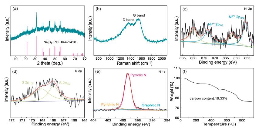
The structural and morphology characterizations of the samples were initially investigated in detail. As demonstrated in Fig. 2a, the strong diffraction peaks of the Ni3S2@NPC match well with the pure crystalline Ni3S2 (PDF #44−1418). Raman spectrum in Fig. 2b reveals two obvious peaks corresponding to the D band and G band of the N-coped carbon layer, respectively. The high ID/IG ratio of 0.93 indicates the carbon materials possess the amorphous structure owing to the porous feature and heteroatom doping. XPS spectra is employed to further characterize the chemical state and components of the Ni3S2/NPC. A pair of peaks at 855.7 and 873.2 eV along with the accompanied satellite peaks give the sign for the existence +2 valence state of Ni in the Ni3S2 (Fig. 2c). The S 2p XPS spectrum exhibits two peaks located at 167.9 and 169.1 eV, which are correlative to the Ni-S bond in the Ni3S2 (Fig. 2d). Furthermore, the N doping with the main pyrrolic-N species is evidently detected from the N 1s and C 1s XPS spectra (Fig. 2e and Fig. S4 in Supporting information). As demonstrated in the present work, the adsorption energy of the electron-rich N sites for sodium is lower than that the pristine carbon skeleton, which will enhance the charge storage located at/nearby the dopants [18, 19]. TGA profile is plotted to record the main four stages of weight loss of the Ni3S2@NPC, as shown in Fig. 2f. A slight weight loss in Stage 1 is ascribed to the evaporation of adsorbed water while the weight loss at the Stages 2 and 3 correspond to the full oxidation of NPC. Finally, the oxidation of Ni3S2 into NiO is responsible for the weight loss at Stages 4. According to the decomposition chemistry, the Ni3S2 takes up 81.7 wt% of the weight ratio in the Ni3S2@NPC. The 5.31 wt% of N content in the Ni3S2@NPC is evaluated through the energy dispersive X-ray spectrum (EDS) shown in Table S1 (Supporting information).

|
Download:
|
| Fig. 2. The chemical composition and structure characterizations of the Ni3S2@NPC. (a) XRD pattern. (b) Raman spectrum. XPS spectra of (c) Ni 2p, (d) S 2p and (e) N 1s. (f) TGA curve. | |
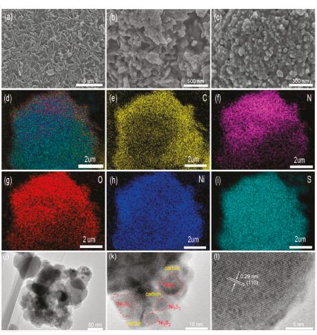
The spindle-shape Ni-MOF with lateral size of around 1 μm is observed from the SEM image in Fig. 3a. After the sulfuration process, the original spindle-like morphology is almost maintained except that the size of every unit shrinks obviously and the surface become rougher (Fig. 3b). Furthermore, the high-resolution SEM image in Fig. 3c presents that the uniform nanoparticles with size lower than 100 nm are stick together through the carbon layer to form continuous conductive network for quick electron transfer. In addition, the obvious pore channels are existed to facilitate the full electrolyte infiltration and quick ion transportation. Noted that, the compact stack of the nanoparticles is conducive to achieve the high loading for active materials. The uniform distribution of C, Ni, and S is witnessed through the elemental mapping measurements in Figs. 3d-i. In addition, the N mapping gives the hint that the heteroatoms are also evenly doped into the porous carbon, agreed with the XPS result. The O heteroatoms may come from the adsorbed water in the Ni-MOF. The in-depth insight into the inner structure of the nanoparticle is performed through the TEM images (Figs. 3j-l). Interestingly, the ultrasmall Ni3S2 nanocrystals with size of only 5−10 nm are casually encapsulated into the porous and amorphous carbon nanoparticles tightly to enable the quick charge transfer between the NPC and Ni3S2. HRTEM image demonstrates the evidence interplanar spacing of 0.29 nm which is well coincided with the (110) plane of the crystalline Ni3S2, further demonstrating the successful preparation of pure Ni3S2 after the low-temperature sulfuration of the scalable Ni-MOF.

|
Download:
|
| Fig. 3. SEM images of (a) Ni-MOF precursor and (b, c) Ni3S2@NPC. (d-i) Elemental mapping of C, N, O, Ni, S for Ni3S2@NPC. (j-l) Different resolution of TEM images of the Ni3S2@NPC. | |
It is well known that the pyrolysis temperature has an important impact on the physicochemical properties of the final products, including the morphology, components, and the particle size. Based on this, a series of samples obtained at the other sulfuration temperatures are prepared. As displayed in Fig. S5 (Supporting information), the XRD patterns of the sample acquired at 350 ℃ are indexed as the pure NiS2 phase (PDF #65−3325), while the diffraction peaks of the samples obtained at 450 ℃ and 500 ℃ are consistent with the crystalline Ni3S2 phase. Therefore, the three samples are denoted as NiS2@NPC-350, Ni3S2@NPC-450, and Ni3S2@NPC-500, respectively. Owing to the low sulfuration temperature, the organic ligands of Ni-MOF can not be full carbonized into porous carbon, as confirmed by the SEM image in Fig. S6a (Supporting information). This phenomenon leads to the blocked charge transfer and thus poor electrochemical reaction kinetics. When improving the sulfuration temperatures from 400 ℃ to 450 ℃ and further to 500 ℃, the size of the nanoparticles become larger gradually, resulting in the increased electrode stress and prolonged charge transfer pathways (Figs. S6b-d in Supporting information). Therefore, it is predicted that the Ni3S2@NPC possesses the superior electrochemical performance to the other three contrast samples benefited from the special nanoengineering design and the functional modification with N-doped carbon nanoparticles.
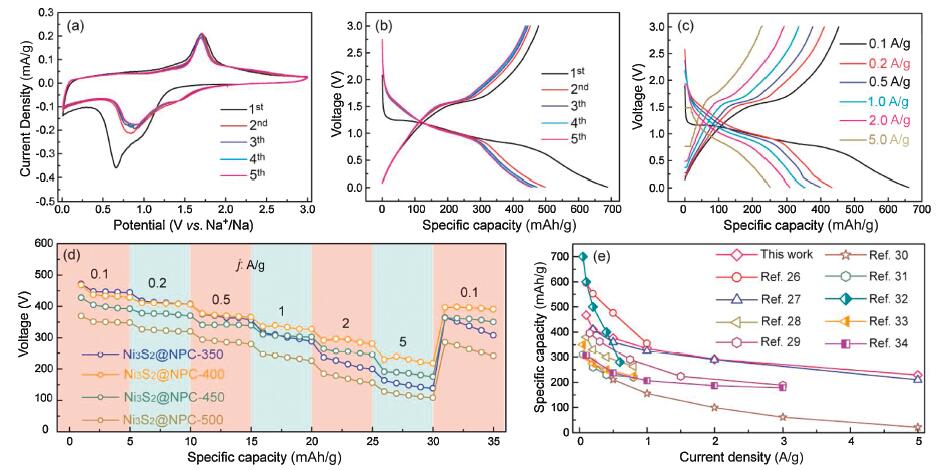
Accordingly, the electrochemical behavior of Ni3S2@NPC is investigated by the CV tests at the scan rate of 0.1 mV/s ranging from 0.01 V to 3 V (Fig. 4a). The unremarkable peak at 1.01 V during the first cathodic scan can be affiliated to the insertion of the Na+ into the Ni3S2@NPC electrode, while the strong reduction peak near 0.65 V is ascribed to the conversion reaction of Ni3S2 into metal Ni and Na2S as well as the formation of the solid electrolyte interface (SEI) film. During the first oxidation process, the sharp peak at 1.7 V corresponds the recovery of Ni3S2. This result is similar to the previous studies of Ni3S2 for SIBs [24, 25]. Remarkably, the reduction peaks during the subsequent cycles shift positively while the oxidation peaks have little change, indicating the decreased polarization because of the full electrolyte infiltration and thus the electrode activation. Besides, the CV profiles remain almost overlapped, suggesting the excellent electrode stability and reversibility for Na+ storage. Fig. 4b exhibits the charge-discharge profiles of the Ni3S2@NPC electrode at 0.1 A/g during the first five cycles. As anticipated, the charge-discharge curves reveal the similar conversion reaction process with the CV results. Specially, a high initial discharge capacity of 689.1 mAh/g is achieved for the Ni3S2@NPC, giving an initial CE of 70.5%. As well known, the irreversible Na+ storage on the NPC and the inevitable formation of SEI film are responsible for the initial capacity loss. In accordance with the CV results, the charge-discharge curves after the first cycles are coincided with each other, further indicating the excellent electrochemical stability. As shown in Fig. S7 (Supporting information), a reversible capacity of 244.2 mAh/g is sustained after 60 cycles at 0.1 A/g. Overall, the NiS2@NPC-350 has obviously different oxidation peaks because of the slight different electrochemical reaction process of NiS2 with Ni3S2 (Fig. S8a in Supporting information). The result is further proved through the charge-discharge curve in Fig. S9 (Supporting information). The initial reversible capacity of NiS2@NPC-350 is slight higher than that of the Ni3S2@NPC owing to the higher theoretical capacity of NiS2. However, the cycle performance is poorer than Ni3S2@NPC because of the incomplete carbonization of the organic ligands in the Ni-MOF, as certified above. Reversely, the Ni3S2@NPC-450 and Ni3S2@NPC-500 show the similar characteristics of CV curves as the Ni3S2@NPC, revealing the same chemical compositions of them (Figs. S8b and c in Supporting information). Clearly, the polarization of the Ni3S2@NPC is smaller than Ni3S2@NPC-450 and Ni3S2@NPC-500 owing to the smaller particle size and thus the more smooth electrochemical reaction and the more stable electrode architecture, which is further confirmed through the smallest charge transfer resistance (Rct) of Ni3S2@NPC from the electrochemical impedance spectra (EIS) result (Fig. S10 in Supporting information). Certainly, the cycle reversibility of the Ni3S2@NPC-450 and Ni3S2@NPC-500 are also poorer than that of the Ni3S2@NPC. Moreover, the Ni3S2@NPC electrode also exhibits desirable rate performance. Fig. 4c gives the proof that the obvious plateaus are well kept at different current densities even at 5 A/g, implying the high-power output. Notably, the reversible capacities of 467.6, 410.3, 376.2, 335.1, 291.2 and 229.1 mAh/g are achieved under the current densities of 0.1, 0.2, 0.5, 1.0, 2.0 and 5.0 A/g, respectively. Moreover, after recovering current density to 0.1 A/g, the electrode can restore the reversible capacity to 396.3 mAh/g, further demonstrating the sustainable electrochemical cycling (Fig. 4d). The rate performance exhibits the distinct competitiveness with respect to the presently reported Ni3S2/C composites in the literatures, as exhibited in Fig. 4e [26-34]. The outstanding rate performance and cycle stability is ascribed to the shortened charge transfer pathways and robust electrode structure owing to the synergy of the ultrasmall size of the Ni3S2 and the tight wrapping by porous N-doped carbon nanoparticles [35-37]. After different cycles, the charge transfer characteristics of Ni3S2@NPC were tracked by EIS measurement, as shown in Fig. S11 (Supporting information). The Rct after the cycle is lower than the initial state. This is due to the stable formation of SEI layer after repeated cycles and the increased contact between the electrode and the electrolyte, which are conducive to the transport of Na+. The Rct has remained stable during different cycles, suggesting the excellent electrode stability and robustness of Ni3S2@NPC. There is no doubt that the rate performance of Ni3S2@NPC-350, Ni3S2@NPC-450 and Ni3S2@NPC-500 is also inferior to Ni3S2@NPC.

|
Download:
|
| Fig. 4. Electrochemical performance of the Ni3S2@NPC electrode. (a) CV curves at different cycles, (b, c) charge-discharge profiles at different cycles and current densities, (d) rate performance at different current densities, (e) the capacities comparison with presently reported Ni3S2/C composites at different current densities. | |
In summary, the nanocomposite composed of the ultrasmall Ni3S2 nanocrystals encapsulated by N-doped porous carbon nanoparticles were prepared with the large-scale Ni-MOF as the precursor. When employed as the anode materials of SIBs, the apparent competitiveness aimed at the cycle stability and rate capacities were well achieved compared with the presently reported Ni3S2/C composites. The excellent storage performance for SIBs can be put down to the synergy of nanoengineering design of the Ni3S2 and the modification of N-doped porous carbon nanoparticles. From one side, the ultrasmall size of Ni3S2 can not only shorten the Na+ diffusion pathways but also decrease the inner stress of the active materials originated from the volume change upon the discharge process. From another side, the N-doped porous carbon layers are profitable to enhance the electron conductivity of electrode and further protect the active Ni3S2 from the corrosion of the electrolyte. As a result, the quick charge transfer channels and the robust electrode structure are well built during cycling. The approach to the large-scale Ni-MOF is also universal to other low-cost and environmentally friendly metal-based MOFs. Therefore, we believe that this study provides a scalable and all-purpose strategy to develop the advanced TMSs for practically feasible SIBs.
Declaration of competing interestThe authors declare that they have no known competing financial interests or personal relationships that could have appeared to influence the work reported in this paper.
AcknowledgmentThis work was financially supported by the National Natural Science Foundation of China (No. 91963118), Fundamental Research Funds for the Central Universities (No. 2412019QD013) and the 111 Project (No. B13013). Dr. C.-Y. Fan gratefully acknowledges the support from China Post doctoral Science Foundation (No. 2019M661191).
Appendix A. Supplementary dataSupplementary material related to this article can be found, in the online version, at doi:https://doi.org/10.1016/j.cclet.2020.07.014.
| [1] |
C. Vaalma, D. Buchholz, M. Weil, et al., Nat. Rev. Mater. 3 (2018) 18013. DOI:10.1038/natrevmats.2018.13 |
| [2] |
P.K. Nayak, L. Yang, W. Brehm, et al., Angew. Chem. Int. Ed. 57 (2018) 102-120. DOI:10.1002/anie.201703772 |
| [3] |
L. Li, Y. Zheng, S. Zhang, et al., Energy Environ. Sci. 11 (2018) 2310-2340. DOI:10.1039/C8EE01023D |
| [4] |
C. Ding, L. Huang, J. Lan, et al., Small 16 (2020) 1906883. DOI:10.1002/smll.201906883 |
| [5] |
J. Pang, R.G. Mendes, A. Bachmatiuk, et al., Chem. Soc. Rev. 48 (2019) 72-133. DOI:10.1039/C8CS00324F |
| [6] |
Y. Li, C. Ou, J. Zhu, et al., Nano Lett. 20 (2020) 2034-2046. DOI:10.1021/acs.nanolett.9b05349 |
| [7] |
Y. Shan, Y. Li, H. Pang, Adv. Funct. Mater. 30 (2020) 2001298. DOI:10.1002/adfm.202001298 |
| [8] |
J.M. Stratford, M. Mayo, P.K. Allan, et al., J. Am. Chem. Soc. 139 (2020) 7273-7286. |
| [9] |
B. Wang, Y. Cheng, H. Su, et al., ChemSusChem 13 (2020) 4078-4085. DOI:10.1002/cssc.202001261 |
| [10] |
Y. Liu, C. Yang, Q. Zhang, et al., Energy Storage Mater. 22 (2019) 66-95. DOI:10.1016/j.ensm.2019.01.001 |
| [11] |
Q. Yun, L. Li, Z. Hu, et al., Adv. Mater. 32 (2020) 1903826. DOI:10.1002/adma.201903826 |
| [12] |
C.Y. Fan, X.H. Zhang, Y.H. Shi, et al., Nanoscale 10 (2018) 18942-18948. DOI:10.1039/C8NR06998K |
| [13] |
X. Liu, F. Zou, K. Liu, et al., J. Mater. Chem. A 5 (2017) 11781-11787. DOI:10.1039/C7TA00201G |
| [14] |
X. Zhao, H.-E. Wang, R.C. Massé, et al., J. Mater. Chem. A 5 (2017) 7394-7402. DOI:10.1039/C7TA01056G |
| [15] |
J. Wang, J. Liu, H. Yang, et al., Nano Energy 20 (2016) 1-10. DOI:10.1016/j.nanoen.2015.12.010 |
| [16] |
H. He, C. Chen, Z. Chen, et al., Sci. China Mater. 63 (2020) 216-228. DOI:10.1007/s40843-019-1175-9 |
| [17] |
W. Qin, T. Chen, T. Lu, et al., J. Power Sources 302 (2016) 202-209. DOI:10.1016/j.jpowsour.2015.10.064 |
| [18] |
J. Li, J. Li, Z. Ding, et al., Chem. Eng. J. 378 (2019) 122108. DOI:10.1016/j.cej.2019.122108 |
| [19] |
X. Ma, X. Xiong, P. Zou, et al., Small 15 (2019) 1903259. DOI:10.1002/smll.201903259 |
| [20] |
C.Y. Fan, X.H. Zhang, Y.-H. Shi, et al., J. Mater. Chem. A 7 (2019) 1529-1538. DOI:10.1039/C8TA09057B |
| [21] |
G.H. Lee, J.K. Kang, Adv. Sci. 7 (2020) 1902986. DOI:10.1002/advs.201902986 |
| [22] |
W. Shuang, H. Huang, L. Kong, et al., Nano Energy 62 (2019) 154-163. DOI:10.1016/j.nanoen.2019.05.030 |
| [23] |
M. Krott, X. Liu, P. Müller, et al., J.Solid State Chem. 180 (2007) 307-312. DOI:10.1016/j.jssc.2006.10.021 |
| [24] |
X. Xia, Q. Wang, Q. Zhu, et al., Mater. Today Energy 5 (2017) 99-106. DOI:10.1016/j.mtener.2017.05.003 |
| [25] |
G.D. Park, J.S. Cho, Y.C. Kang, Nanoscale 7 (2015) 16781-16788. DOI:10.1039/C5NR04252F |
| [26] |
M.C. Liu, J. Li, Q.Q. Yang, et al., ACS Appl. Nano Mater. 2 (2019) 2634-2641. DOI:10.1021/acsanm.8b02341 |
| [27] |
X. Chang, Y. Ma, M. Yang, et al., Energy Storage Mater. 23 (2019) 358-366. DOI:10.1016/j.ensm.2019.04.039 |
| [28] |
X. Song, X. Li, Z. Bai, et al., Carbon 133 (2018) 14-22. DOI:10.1016/j.carbon.2018.02.101 |
| [29] |
J. Tang, S. Ni, D. Chao, et al., Electrochim. Acta 265 (2018) 709-716. DOI:10.1016/j.electacta.2018.01.199 |
| [30] |
T. Du, H. Zhu, B.B. Xu, et al., ACS Appl. Energy Mater. 2 (2019) 4421-4427. DOI:10.1021/acsaem.9b00669 |
| [31] |
X. Song, X. Li, Z. Bai, et al., Adv. Mater. Interfaces 5 (2018) 1701684. DOI:10.1002/admi.201701684 |
| [32] |
X. Xia, J. Xie, S. Zhang, et al., J. Mater. Sci. Technol. 33 (2017) 775-780. DOI:10.1016/j.jmst.2016.09.017 |
| [33] |
X. Song, X. Li, Z. Bai, et al., Nano Energy 26 (2016) 533-540. DOI:10.1016/j.nanoen.2016.06.019 |
| [34] |
J. Li, J. Li, T. Chen, et al., Inorg. Chem. Front. 6 (2019) 694-704. |
| [35] |
Z.Y. Gu, J.Z. Guo, Z.H. Sun, et al., Sci. Bull. 65 (2020) 702-710. DOI:10.1016/j.scib.2020.01.018 |
| [36] |
X. Yan, C.Y. Fan, X. Yang, et al., Mater. Today Energy 13 (2019) 302-307. DOI:10.1016/j.mtener.2019.06.002 |
| [37] |
Y.Y. Wang, B.H. Hou, J.Z. Guo, et al., Adv. Energy Mater. 8 (2018) 1703252. DOI:10.1002/aenm.201703252 |