 2021, Vol. 32


The development and demand of portable electronic and electric vehicles puts forward higher requirements for electrochemical energy storage [1-3]. Ion diffusion kinetics greatly affects the rate performance, which is the key metric of electrochemical energy storage [4-7]. Ion diffusion kinetics depends on the size, tortuosity, connectivity of the ion channels in the electrodes [8-12]. Various strategies have been explored to mediate the porosity of electrode materials, such as reducing the materials to the nanometer scale [13, 14], templating synthesis [15-17] and sol–gel chemistry techniques [18, 19].
Recently, Two-dimensional materials (2DMs) have shown great promise for electrochemical energy storage [20-23]. As one of the representatives, MoS2 has attracted increasing research interest because its interlayer can provide sites for ion storage and allow reversible de/intercalation of ions [24-27]. However, the practical applications of MoS2 nanosheets anodes are limited by the restacking of 2D nanosheets due to the strong van der Waals attraction, which causes a poor rate capability [28-30]. Various structural design strategies have been developed to address this issue [31-35]. For example, Gogotsi and co-workers fabricated a free-standing MoS2@carbon paper electrode featured with a hierarchical structure, in which MoS2 nanosheets are vertically aligned on carbon scaffolds, effectively avoiding their aggregation to enable sufficient electrode/electrolyte interaction and excellent rate capability for sodium-ion batteries [36]. Lou and co-workers synthesized hierarchical MoS2microboxes constructed by ultrathin nanosheets with highly exposed active edge sites and large specific surface area, which manifest excellent electrochemical properties as anode materials for lithium-ion batteries [37]. Nevertheless, due to the rigidity, the absence of functional groups and insufficient bonding sites of MoS2 nanosheets, it is still a challenge to achieve the direct assembly of individual MoS2 sheets without compromise in its surface accessibility [38, 39].
The nanosheet morphologies are critical in designing multiscale structures and performances of macroscopic materials [40]. Typically, Huang's group reported that compared with flat or wrinkled sheets, the crumpled graphene "paper balls", which can resist compression from any direction without unfolding, deliver much higher specific capacitance and better rate performance [28]. The hierarchically wrinkled morphology by poor solvents enabled the fabrication of amorphous self-standing graphene papers with a rubber-like mechanical behavior with viscoelasticity [41]. The morphology mediation of MoS2 nanosheets should be an effective approach to realize MoS2 electrodes with high rate performance.
Herein, we investigated the morphology mediation of MoS2 nanosheets via a facile coagulation method to solve the strong restacking problem of 2DMs. Importantly, the organic cations of ionic liquids, (1-butyl-3-methylimidazolium tetrafluoroborate ([BMIM]BF4), caused edge/face contact of the sheets and afforded a house-of-cards structure, instead of the dense sediments with the face/face contact caused by the alkali/alkaline-earth cations (Mg2+, K+). This restacked-resistant structure with abundant mesopores possesses the interconnected ion transport channel, thereby ensuring the accessibility of electrode materials and shortening the length of Na-ion diffusion paths. Benefitting from these advantages, the MoS2-[BMIM]+ electrode exhibits superior rate performance for Na-ion storage.
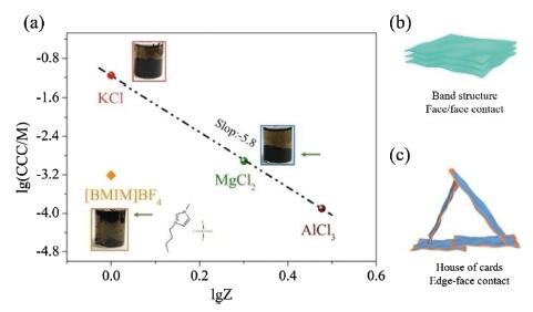
The average in-plane size and thickness of MoS2 nanosheets are 154.58 and 0.73 nm, counted from that of 53 sheets from their atomic force microscopy images (Fig. S1 in Supporting information). Due to the electron injection during the lithium intercalation process, the prepared MoS2 nanosheets were highly negatively charged and can form stable colloids in water. Their colloidal stability relies on a low ion-strength environment. Adding electrolytes into the dispersion can easily cause their aggregation. We compared the coagulation effect of inorganic salts (KCl, MgCl2) and organic salt ([BMIM]BF4) (Fig. 1 and Fig. S2 in Supporting information). For KCl and MgCl2, the relationship between the measured critical coagulation concentration (CCC) and cation valence almost follows the Schulze-Hardy law (CCC∝Z−6) [42]. Interestingly, the CCC of [BMIM]BF4 was much smaller than the value predicted by the law. We propose there are two possible reasons underlying this deviation. One is that [BMIM]+ holds a specific adsorption (chemical interaction) with the MoS2 nanosheets, which makes it concentrated on the sheet surface to facilitate the charge screening. The other is that [BMIM]+ causes an edge/basal-plane contact, instead of the face/face contact. Upon the addition of [BMIM]BF4, zeta potential (ς) increases monotonically with electrolyte concentration(ς0 mol/L =−53.35 mV to ς0.0028 mol/L =−37.53 mV). Instead, when KCl is added, the ς is found not tochange substantially (ς0 mol/L =−53.35 mV to ς0.0028 mol/L =−50.13 mV). Obviously, [BMIM]+ has stronger adsorption than inorganic cation K+, which is beneficial to charge screening [43].

|
Download:
|
| Fig. 1. (a) The critical coagulation concentration (CCC) plotted with the valence of cations (Z). The insets are the optical photos of the coagulated MoS2 colloids. The MoS2 aggregates with [BMIM]BF4 appeared as floated clusters of flocs, while that by KCl and MgCl2 appeared as sediments. The specific adsorption (due to chemical interaction) of [BMIM]+ on MoS2 nanosheets, or probably MoS2 nanosheet edge, makes its CCC largely deviate from Schulze-Hardy law (CCC∝Z−6). (b, c) The schematic illustration of (b) band structure and (c) house-of-cards structure. | |
Schulze-Hardy law is the derivate of Derjaguin-Landau-Verwey-Overbeek (DLVO) theory, in which the 2D sheets are treated as homogeneously charged tablets. The ion strength should increase to CCC to sufficiently weaken the repulsive electrostatic force, which cause the face/face stacking (Fig. 1b). In the case of MoS2 nanosheets, the edge and basal plane (i. e., face) share different properties. The edge comprises poorly coordinated Mo atoms, while the basal plane comprises well-coordinated ones. The edge shows a higher surface energy and polarity than that of the basal plane [44]. When associating with cations, the edge is prone to undergoing a charge reversal ahead of the basal [45]. Then the edge and basal plane hold opposite charge sign, coagulation happens under an edge-face contact with a house-of-cards structure (Fig. 1c), without the need to overcome the inter-sheet repulsion. With this configuration, the CCC would be below the value predicted by Schulze-Hardy law. Note that the MoS2 aggregates with [BMIM]BF4 appeared as floated clusters of flocs, while those with KCl and MgCl2 appeared as sediments. This phenomenon supports the assumption that [BMIM]+ induces a coagulation with house-of-cards structure. To verify this assumption, we investigated the microstructure of the aggregates with different electrolytes (Fig. 2).

|
Download:
|
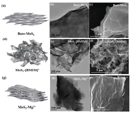
| Fig. 2. Microstructures of (a-c) bare-MoS2, (d-f) MoS2-[BMIM]+ and (g-i) MoS2-Mg2+. (a, d, g) Schematic illustration. (b, e, h) TEM images. (c, f, i) SEM images. | |
The typical TEM image (Fig. 2b) showed that the directly dried MoS2 (denoted as bare-MoS2) exhibits a smooth surface and large-area restacking. For MoS2-Mg2+ (Fig. 2h), seen from the edges of the aggregates, they consist of thinner MoS2 laminate than that of bare-MoS2. In sharp contrast, the aggregates from MoS2-[BMIM]+ appeared much thinner thoroughly; vivid folds can be found throughout the aggregates (Fig. 2e). SEM image of bare-MoS2 also showed their thick laminates without noticeable wrinkles (Fig. 2c and Fig. S3 in Supporting information), while for MoS2-Mg2+, micrometers-long wrinkles can be found. In sharp contrast, the aggregates of MoS2-[BMIM]+ showed a porous structure with folded thin MoS2 laminates as the pore walls. We can infer that the porous structure is originated from the partially compressed house-of-cards structure; the van der Waals force forces the strut sheets to restack, while the high bending modulus of the MoS2 sheets/laminates would resist the restacking. The folded morphology of the nanosheets/laminates indicates restack still happens locally, which, however, could resist further restacking with other laminates [28]. MoS2-K+ showed the similar morphology as MoS2-Mg2+ (Fig. S4 in Supporting information).
Element mapping images of MoS2-[BMIM]+ and MoS2-Mg2+ samples are shown in Fig. S5 (Supporting information), in which the uniform distribution of N and Mg in MoS2 nanosheets can be evidenced. Fig. S6 (Supporting information) shows the XRD patterns of bare-MoS2, MoS2-[BMIM]+, MoS2-Mg2+ and MoS2-K+. The diffraction peak of bare-MoS2 located at 14.5°, corresponding to an interlayer distance of 6.15 Å and matched with the (002) reflection. After associated with [BMIM]+, Mg2+ and K+, the new (002) diffraction peak and (004) diffraction peak appeared, and the interlayer spacing expanded to 10.0 Å, 11.8 Å and 9.3 Å, respectively.
As shown in Fig. S7a (Supporting information), the MoS2-[BMIM]+ shows a type IV isotherm curve with a hysteresis loop, indicating the existence of a mesoporous structure [32]. The Brunauer-Emmett-Teller (BET) surface area of the MoS2-[BMIM]+ was 33.11 m2/g, which is four times that of the bare-MoS2 (7.98 m2/g). The pore size distributions were derived from the Barrett-Joyner-Halenda (BJH) method (Fig. S7b in Supporting information). The pore size of bare-MoS2 was concentrated at 2 nm, while that of MoS2-[BMIM]+ was at 3 nm accompanied by a dispersive peak centered at 20 nm. In addition, the surface areas of MoS2-Mg2+ and MoS2-K+ were 2.04 and 2.35 m2/g, respectively (Figs. S7c and d in Supporting information). To further demonstrate the superior surface accessibility of MoS2-[BMIM]+, we measured the electric double layer capacitance (Cdl) at the potential range of 2.80−2.90 V vs. Na+/Na (Fig. S8 in Supporting information), which is known to be proportional to the effective electrochemical surface area [46]. The Cdl of bare-MoS2, MoS2-[BMIM]+ and MoS2-Mg2+ were 1.0, 2.9 and 0.51 F/g, respectively. Both the N2 adsorption/desorption measurement and electrochemical active surface area conform the advantage of MoS2 nanosheets with a crumpled morphology. For electrode materials, such porosity can not only reduce the ions diffusion length, but also provide enough buffer space to mitigate the volume change during the charging/discharging [32].
We investigated the phase composition of bare-MoS2 and MoS2-[BMIM]+ by XPS (Fig. S9 in Supporting information). For bare-MoS2, the high-resolution Mo 3d and S 2p spectra verified the presence of 2H MoS2 and 1T MoS2, the peaks at 228.98, 232.08, 161.78 and 163.18 eV correspond to Mo 3d5/2, Mo 3d3/2, S 2p3/2 and S 2p1/2 components of 2H MoS2, and the peaks at 228.38, 231.48, 161.28 and 162.58 eV correspond to Mo 3d5/2, Mo 3d3/2, S 2p3/2 and S 2p1/2 components of 1T MoS2. Similarly, for MoS2-[BMIM]+, all peaks for 2H MoS2 and 1T MoS2 were observed, indicating that [BMIM]+ does not alter the phase composition of MoS2 nanosheets.
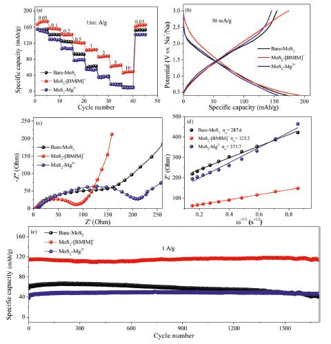
Fig. 3 presented the sodium-ion storage performance under a cut-off voltage (0.4−3 V), because conversion reaction of MoS2 starts at 0.4 V vs. Na+/Na and leads to poor structure stability. The capacity differences between MoS2-[BMIM]+ and bare-MoS2, MoS2-Mg2+ electrodes became more pronounced along with the increase of current densities from 0.05 A/g to 10 A/g (Fig. 3a). Even at a high current density of 10 A/g, the reversible capacity reached 48 mAh/g, while the bare-MoS2 and MoS2-Mg2+ electrodes showed almost no capacity. In detail, Fig. 3b displayed the voltage profiles during the fifth charge–discharge cycle at 50mA/g. The discharge-specific capacities of the bare-MoS2, MoS2-[BMIM]+ and MoS2-Mg2+ anodes were 172, 194 and 157 mAh/g, respectively. In addition, the galvanostatic charging/discharging profiles of MoS2-[BMIM]+ at different densities are shown in Fig. S10 (Supporting information) and the electrochemical performance of MoS2-K+ is shown in Fig. S11 (Supporting information).

|
Download:
|
| Fig. 3. Electrochemical performance. (a) Rate performances. (b) Galvanostatic charge-discharge at 50 mA/g. (c) Nyquist plots. (d) The real part of the impedance plotted against ω−1/2 at low frequency region. (e) Cycling performance at 1 A/g. | |
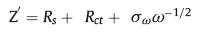
To further examine the ion diffusion kinetics, the electrochemical impedance spectroscopy (EIS) was performed at the potential of 3.0 V (vs. Na+/Na) (Fig. 3c). The curve of MoS2-[BMIM]+ delivered a much smaller diameter of the depressed semicircle in high and middle frequency regions than that of bare-MoS2 and MoS2-Mg2+, implying its superior charge transfer efficiency. The plots of Z' vs. ω−1/2 are shown in Fig. 3d. According to the formula,
|
(1) |
the Warburg coefficient σω can be obtained from the slope of the plots. The Warburg coefficient σω of MoS2-[BMIM]+ anode was 123.2 Ω cm2 s−1/2, which is much smaller than the bare-MoS2 (287.6 Ω cm2 s−1/2) and MoS2-Mg2+ (373.7 Ω cm2 s−1/2). Since the diffusion coefficient of the carrier ions in the electrode material is inversely proportional to the square of the Warburg coefficient [11], we can deduce that the MoS2-[BMIM]+ anode exhibits a larger ion diffusion coefficient. The initial specific capacity was 114.7 mAh/g, and maintained 114.3 mAh/g after 1700 cycles at 1 A/g with the capacity retention of 99.7%. The MoS 2-[BMIM]+ still presented the same porous structure after cycling, as shown in Figs. S12 and S13 (Supporting information). In contrast, the specific capacity of bare-MoS2 decreased to 44 mAh/g after 1700 cycles with a capacity retention of 75.1%. MoS2-Mg2+ showed the lowest initial capacity among the three but delivered a high capacity retention (42 mAh/g at 2nd cycle and 46.7 mAh/g at 1700th cycle), which can be ascribed to the inefficient pore utilization at the beginning (Fig. 3e).
To determine the charge storage mechanism of MoS2-[BMIM]+ anode, we perform a detailed quantitative analysis [47] of its rate performance (Fig. 4). The CV curves at various scan rate showed a similar shape; the redox peak difference did not increase significantly along with the increase of scan rates (v, mV/s), indicating a small electrochemical polarization (Fig. 4a). The current (i, mA) at different potential is plotted with v (Fig. 4b). The i can be expressed as follows,

|
Download:
|
| Fig. 4. Electrochemical reaction kinetics of MoS2-[BMIM]+ electrodes. (a) CV curves at different scan rates. (b) The current density at the peak potential in (a) plotted against scan rates. (c) Capacitive contribution at different scan rates. (d) CV profile at 1 mV/s. The capacitance and diffusion-controlled contribution are filled green and red. | |

|
(2) |
where k1 and k2 are the coefficient of capacitance-controlled and diffusion-controlled processes, respectively. As shown in Fig. 4b, lg i was linearly fitted with lg v, and the slop, denoted as b, at the three redox peaks were 0.92, 0.87 and 0.9. One can expect that when the b approaches 1, the charge storage is mainly non-diffusion-limited capacitive process, and when the b is close to 0.5, the diffusion-limited process dominates. We can infer that the charge storage of MoS2-[BMIM]+ is a hybrid process of capacitance control and diffusion control, and the capacitive Na+ storage is the dominant. The quantitative capacitive contribution of MoS2-[BMIM]+ at different scan rate is shown in Fig. 4c, MoS2-[BMIM]+ electrode showed a much higher capacitive contribution (72%, Fig. 4d) than the bare-MoS2 electrode (40%, Fig. S14 in Supporting information) at the low scan rate of 1 mV/s. These results clearly demonstrate that the highly open and interconnected pores in MoS2-[BMIM]+ electrodes make the surface more accessible and shorten the diffusion path of ions [47, 48].
We also examined the validity of MoS2-[BMIM]+ in the full cells. We assembled the MoS2-[BMIM]+ as anodes and commercial activated carbon (AC) as cathodes to form a sodium-ion hybrid capacitor. The electrochemical performances were tested within the voltage window of 1.0–3.7 V to avoid the electrolyte decomposition and the conversion reaction of MoS2. The mass ratio of MoS2-[BMIM]+ anodes and AC cathodes is optimized to 1:4, to achieve the charge balance of the two electrodes. CVs between 0.5−10 mV/s are shown in Fig. S15a (Supporting information).
The near-rectangular CV curves and the almost symmetrical linear curves of the galvanostatic charge/discharge profiles (Fig. S15c in Supporting information) demonstrate its capacitance-control charge storage mechanism and fast ion diffusion capability. The hybrid capacitor delivers a good rate performance with a discharge capacity of 84.8 mAh/g at 0.2 A/g and 36.1 mAh/g at 5 A/g. Furthermore, this hybrid capacitor preserves a capacity retention of 83.9% at a high current density of 1 A/g after 300 cycles (Figs. S15b and d in Supporting information).
In summary, to overcome the restacking of MoS2 nanosheets, we mediate their morphology through a facile coagulation strategy. The addition of organic cations [BMIM]+ induces the MoS2 nanosheets to flocculate, resulting in the crumpled morphology and porous structure. We propose that organic cations cause edge/face contact of the sheets, thus affording a house-of-cards structure. In contrast, the alkali/alkaline-earth ions cause the sheets to remain the extended morphology, forming the dense sediments in which the face/face contact dominates. The MoS2-[BMIM]+ shows a high-performance as the anode material for Na-ion storage. The porous microstructure and the crumpled morphology of MoS2 nanosheets greatly benefit the ion transport kinetics through shortening the sodium ion transport path length and enhancing surface accessibility. This work provides a novel strategy for the morphology mediation of MoS2 nanosheets and structure design of macroscopic materials to enhance ion diffusion kinetics.
Declaration of competing interestThe authors declare that they have no known competing financial interests or personal relationships that could have appeared to influence the work reported in this paper.
AcknowledgmentThis work was supported by the National Natural Science Foundation of China (Nos. 21938005 and 21905206).
Appendix A. Supplementary dataSupplementary material related to this article can be found, in the online version, at doi:https://doi.org/10.1016/j.cclet.2020.06.036.
| [1] |
G. Crabtree, Nature 526 (2015) S92. DOI:10.1038/526S92a |
| [2] |
A. Farmann, W. Waag, D.U. Sauer, Energy 112 (2016) 294-306. DOI:10.1016/j.energy.2016.06.088 |
| [3] |
Z.Y. Chen, R. Xiong, J.Y. Cao, Energy 96 (2016) 197-208. DOI:10.1016/j.energy.2015.12.071 |
| [4] |
M. Park, X.C. Zhang, M.D. Chung, G.B. Less, A.M. Sastry, J. Power Sources 195 (2010) 7904-7929. DOI:10.1016/j.jpowsour.2010.06.060 |
| [5] |
S.P. Ong, V.L. Chevrier, G. Hautier, et al., Energ Environ. Sci. 4 (2011) 3680-3688. DOI:10.1039/c1ee01782a |
| [6] |
Y. Sun, X. Liang, H.F. Xiang, Y. Yu, Chin. Chem. Lett. 28 (2017) 2251-2253. DOI:10.1016/j.cclet.2017.11.028 |
| [7] |
M. Guo, W.Y. Zhao, H.L. Dou, et al., ACS Appl. Mater. Interfaces 11 (2019) 27024-27032. DOI:10.1021/acsami.9b09853 |
| [8] |
D.W. Wang, F. Li, M. Liu, G.Q. Lu, H.M. Cheng, Angew. Chem. Int. Ed. 47 (2008) 373-376. DOI:10.1002/anie.200702721 |
| [9] |
G.W. Sun, J.T. Wang, X.J. Liu, et al., J. Phys. Chem. C 114 (2010) 18745-18751. DOI:10.1021/jp106205n |
| [10] |
D.R. Rolison, Science 299 (2003) 1698-1701. DOI:10.1126/science.1082332 |
| [11] |
M. Guo, J.C. Wang, H.L. Dou, et al., Nano Energy 56 (2019) 502-511. DOI:10.1016/j.nanoen.2018.11.091 |
| [12] |
C. Liu, X. Yan, F. Hu, et al., Adv. Mater 30 (2018) 1705713. DOI:10.1002/adma.201705713 |
| [13] |
Y. Xiao, S.H. Lee, Y.K. Sun, Adv. Energy Mater. 7 (2017) 1601329. DOI:10.1002/aenm.201601329 |
| [14] |
X. Yan, H. Ye, X.L. Wu, et al., J. Phys. Chem. A 5 (2017) 16622-16629. |
| [15] |
A. Walcarius, Chem. Soc. Rev. 42 (2013) 4098-4140. DOI:10.1039/c2cs35322a |
| [16] |
Y.J. Zhang, L.H. Lu, Z. Zhang, et al., Chin. Chem. Lett. 29 (2018) 641-644. DOI:10.1016/j.cclet.2017.10.030 |
| [17] |
S.L. Yang, B.H. Zhou, M. Lei, et al., Chin. Chem. Lett. 26 (2015) 1293-1297. DOI:10.1016/j.cclet.2015.05.051 |
| [18] |
N. Linares, A.M. Silvestre-Albero, E. Serrano, J. Silvestre-Albero, J. GarciaMartinez, Chem. Soc. Rev. 43 (2014) 7681-7717. DOI:10.1039/C3CS60435G |
| [19] |
T. Chen, W.F. Liu, Y. Zhuo, et al., Chem. Eng. J. 383 (2020) 123087. DOI:10.1016/j.cej.2019.123087 |
| [20] |
Y.H. Xue, Q. Zhang, W.J. Wang, et al., Adv. Energy Mater. 7 (2017) 1602684. DOI:10.1002/aenm.201602684 |
| [21] |
Y. Zhu, L.L. Peng, Z.W. Fang, et al., Adv. Mater. 30 (2018) 1706347. DOI:10.1002/adma.201706347 |
| [22] |
C.C. Liu, X.L. Zhao, S.P. Wang, et al., ACS Appl. Energ. Mater. 2 (2019) 4458-4463. DOI:10.1021/acsaem.9b00699 |
| [23] |
Y. Liu, D.P. Zhao, H.Q. Liu, A. Umar, X. Wu, Chin. Chem. Lett. 30 (2019) 1105-1110. DOI:10.1016/j.cclet.2018.12.024 |
| [24] |
H. Yoo, A.P. Tiwari, J. Lee, et al., Nanoscale 7 (2015) 3404-3409. DOI:10.1039/C4NR06348A |
| [25] |
M. Chhowalla, H.S. Shin, G. Eda, et al., Nat. Chem. 5 (2013) 263-275. DOI:10.1038/nchem.1589 |
| [26] |
Q.H. Wang, K. Kalantar-Zadeh, A. Kis, J.N. Coleman, M.S. Strano, Nat. Nanotechnol. 7 (2012) 699-712. DOI:10.1038/nnano.2012.193 |
| [27] |
F. Chen, L. Wu, Z.P. Zhou, et al., Chin. Chem. Lett. 30 (2019) 197-202. DOI:10.1016/j.cclet.2018.10.007 |
| [28] |
J.Y. Luo, H.D. Jang, J.X. Huang, ACS Nano 7 (2013) 1464-1471. DOI:10.1021/nn3052378 |
| [29] |
C.D. Zangmeister, X.F. Ma, M.R. Zachariah, Chem. Mater. 24 (2012) 2554-2557. DOI:10.1021/cm301112j |
| [30] |
Z.Y. Guo, Y. Zhong, Y. Liu, C.M. Mao, G.C. Li, Chin. Chem. Lett. 28 (2017) 743-747. DOI:10.1016/j.cclet.2016.10.007 |
| [31] |
Q.B. Yun, Q.P. Lu, X. Zhang, C.L. Tan, H. Zhang, Angew. Chem. Int. Ed. 57 (2018) 626-646. DOI:10.1002/anie.201706426 |
| [32] |
X. Hu, Y. Li, G. Zeng, et al., ACS Nano 12 (2018) 1592-1602. DOI:10.1021/acsnano.7b08161 |
| [33] |
W.N. Ren, H.F. Zhang, C. Guan, C.W. Cheng, Adv. Funct. Mater. 27 (2017) 1702116. DOI:10.1002/adfm.201702116 |
| [34] |
L. David, R. Bhandavat, G. Singh, ACS Nano 8 (2014) 1759-1770. DOI:10.1021/nn406156b |
| [35] |
B.A. Chen, H.H. Lu, J.W. Zhou, et al., Adv. Energy Mater. 8 (2018) 1702909. DOI:10.1002/aenm.201702909 |
| [36] |
X.Q. Xie, T. Makaryan, M.Q. Zhao, et al., Adv. Energy Mater. 6 (2016) 1502161. DOI:10.1002/aenm.201502161 |
| [37] |
L. Zhang, H.B. Wu, Y. Yan, X. Wang, X.W. Lou, Energy Environ. Sci. 7 (2014) 3302-3306. DOI:10.1039/C4EE01932F |
| [38] |
Z.Y. Wang, Q.S. Tu, S.X. Zheng, et al., Nano Lett. 17 (2017) 7289-7298. DOI:10.1021/acs.nanolett.7b02804 |
| [39] |
Y.Q. Deng, C. Luo, J. Zhang, et al., Sci. China Mater. 62 (2019) 745-750. DOI:10.1007/s40843-018-9363-7 |
| [40] |
D. Zhao, M. Clites, G.B. Ying, et al., Chem. Commun. 54 (2018) 4533-4536. DOI:10.1039/C8CC00649K |
| [41] |
Y. Xiao, Z. Xu, Y. Liu, et al., ACS Nano 11 (2017) 8092-8102. DOI:10.1021/acsnano.7b02915 |
| [42] |
M. Sano, A. Kamino, S. Shinkai, J. Phys. Chem. B 104 (2000) 10339-10347. DOI:10.1021/jp002387y |
| [43] |
D. Penner, G. Lagaly, Clays Clay Min. 48 (2000) 246-255. DOI:10.1346/CCMN.2000.0480211 |
| [44] |
Z.Z. Lu, J. Ralston, Q.X. Liu, J. Phys. Chem. C 124 (2020) 372-381. DOI:10.1021/acs.jpcc.9b07632 |
| [45] |
B.K. Miremadi, T. Cowan, S.R. Morrison, J. Appl. Phys. 69 (1991) 6373-6379. DOI:10.1063/1.348839 |
| [46] |
S. Gong, G.Y. Zhao, P.B. Lyu, K.N. Sun, J. Mater. Chem. A 7 (2019) 1187-1195. DOI:10.1039/C8TA08120D |
| [47] |
J.B. Cook, H.S. Kim, Y. Yan, et al., Adv. Energy Mater. 6 (2016) 1501937. DOI:10.1002/aenm.201501937 |
| [48] |
X. Xu, R. Zhao, W. Ai, et al., Adv. Mater 30 (2018) 1800658. DOI:10.1002/adma.201800658 |