 2021, Vol. 32


Porous carbon materials have been widely used in the fields of adsorption, catalysis, carrier and electrochemical energy storage due to their high chemical stability, good conductivity and low price [1-5]. The introduction of porous structure into carbon matrix is often realized by the use of specific templates as the porogens. These templates are generally divided into two categories according to their phase state, i.e., non-solid template (soft template) and solid template (hard template) [6-8]. For soft template method, the soft templates usually need to be formed in-situ during the synthesis process so that the formation and the structure of the pores are limited to some extent [9-12]. For example, Liu et al. prepared mesoporous carbon foams by adding surfactant sorbitan monooleate into the ethanol solution of phenol and formaldehyde. The micelles were formed by the surfactant in the system under stirring. After the crosslinking polymerization of monomers followed by a carbonization process, mesoporous carbon foams with a pore size of 4 nm, which was in keeping with the size of micelle formed by the surfactant, were obtained [13]. Hard templates are usually prepared in advance. After they combine with the carbon precursors, the complexes go through a carbonizing process to form carbon matrix and remove the hard templates, resulting in the production of porous carbon materials with the predesigned pore structures [14, 15]. For example, Yu et al. used a colloidal crystal block formed by the assembly of 200-nm solid SiO2 nanoparticles as the hard template, in which phenol and formaldehyde were infiltrated to in situ polymerize into crosslinked phenolic polymer that was utilized as the carbon source. After the treatment of carbonization and the etching of SiO2, carbon blocks with highly ordered uniform pores were prepared [16]. Compared to soft template method, hard template method has great advantages in the diversity of template types and the flexible design of the structure because the hard templates can be synthesized separately in advance according to the requirements [17-20]. Therefore, hard template method is more widely used in the preparation of porous carbon materials. Obviously, based on the pore-formation mechanism of the template method, the pore structure of the final porous carbon material products entirely depends on the template structure. Hence, the design and preparation of novel hard templates are critical for the development of porous carbon material.
As defined by the international union of pure and applied chemistry (IUPAC), porous materials can be divided into three categories according to the pore size: macroporous (> 50 nm), mesoporous (2~50 nm) and microporous (< 2 nm) materials [21]. Limited by the structure of the template, most porous carbon materials have a single pore size distribution. For example, the size of soft micelle templates is generally smaller than 50 nm. As a result, the pore formed from the micelle generally has a scattered uniform meso-pores in the matrix [22-24]. While the size of solid hard template is generally larger than 50 nm, so most of the products obtained from hard templates are macroporous carbon materials [25, 26]. In some practical applications, the single pore size distribution of porous materials brings some limitations. In order to prepare porous materials with better permeability, larger pore volume and higher specific surface area, it is desired to introduce multi-level pore structure such as macropore and mesopore into carbon materials, which raises the new requirements for the structure design of the template materials.
On the other hand, some active sites are desirable to be introduced into the carbon matrix to expand more specific properties and functions. It has been reported that nitrogen doping could adjust the electronic structure and change some physical and chemical properties of carbon materials to improve their performance [27-29]. For example, Xie et al. prepared polyacrylonitrile-coated fibrous silica microspheres with a size of about 300 nm [30]. After the carbonization treatment and etching of fibrous silica template, N-doped porous carbon microspheres with 286 nm were obtained. Due to the incorporation of nitrogen atoms, the prepared porous carbon microspheres exhibit better dispersibility in polar solvents (such as water) and a more excellent adsorption ability towards small molecules (such as rhodamine B). However, the submicron-sized microspheres are too small to separate from the system, which is not conducive to actual recycling of the adsorbents.
According to the above consideration, the preparation of high-performance hierarchical porous carbon materials with functional sites is still worth of further research. In this work, novel micron-sized inverse-opal N-doped carbon (IO-NC) microspheres consisting of hollow carbon nanoparticles with a hierarchical macro/meso-porous inner surface were constructed. IO-NC microspheres were prepared using a new porous colloidal crystal microsphere as the template, which consists of fibrous silica (F-SiO2) nanoparticles. The polymerization of acrylonitrile (AN) was in-situ induced by 60Co γ-ray radiation since it can be achieved at room temperature so as to avoid the damage to the structure of the colloidal crystal microsphere template caused by the high temperature for chemical-initiated polymerization. The IO-NC microspheres have a high specific surface area of 266.4 m2/g and a high nitrogen content with a molar ratio of C/N of 5. They can be well dispersed in water, and show a high adsorption capacity towards rhodamine B (RhB) up to 137.28 mg/(g microsphere). This work provides a new idea to prepare high-performance hierarchical porous N-doped carbon materials.
According to our previous work [31, 32], F-SiO2 nanoparticles are firstly prepared by the hydrolysis condensation of TEOS in the emulsion containing CTAB, cyclohexane and water to construct colloidal microsphere template, as shown in Fig. S1a (Supporting information). It can be seen that the nanoparticles seem to be constituted by radial fibers. The average size of the F-SiO2 nanoparticles is 230 nm. The FTIR spectrum of the F-SiO2 nanoparticles in Fig. S1b (Supporting information) shows the characteristic absorptions of the asymmetric stretching vibration of Si-O-Si (1090 cm-1), the stretching vibration of Si-O-Si (805 cm-1), the bending vibration of Si-O-Si (466 cm-1), in-plane stretching vibration of Si-OH (962 cm-1), the deformation vibration of the adsorbed water molecules (1635 cm-1) and O-H stretching vibration (~ 3500 cm-1), indicating that the F-SiO2 nanoparticles have large number of hydroxyl group and good hydrophilicity. The peaks at 2858 cm-1, 2930 cm-1, 1382 cm-1 and 1473 cm-1 are assigned to be the stretching and the bending vibrations of saturated C-H bonds mainly on the alkyl chain of CTAB.
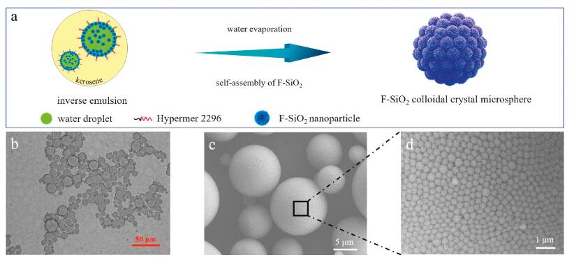
Based on our previous work of preparing colloidal crystal microsphere in the inverse emulsion system [33, 34], F-SiO2 nanoparticles are used as the self-assembly unit in this work and the formation of F-SiO2 colloidal crystal microsphere is illustrated in Fig. 1a. The as-prepared F-SiO2 nanoparticles have a zeta potential of -21.63 mV. Thus, they can be dispersed well in water, and then mixed with kerosene containing high-performance non-ionic emulsifier Hypermer 2296 to form an inverse emulsion, as shown in Fig. 1b. The water droplets containing F-SiO2 nanoparticles with a size of 5~20 μm are dispersed stably in kerosene.

|
Download:
|
| Fig. 1. (a) Schematic illustration of the formation of F-SiO2 colloidal crystal microsphere. (b) Optical microscope image of the inverse emulsion consisting of F-SiO2 nanoparticles, water, Hypermer 2296, and kerosene. (c) SEM image of F-SiO2 colloidal crystal microspheres. (d) The enlarged SEM image of a part of the surface of a F-SiO2 colloidal crystal microsphere in (c). | |
The inverse emulsion is kept at a relatively high temperature (50 ℃) to let water evaporate steadily, which drives the F-SiO2 nanoparticles distributed in each water droplet to assemble gradually. Finally, when water has been evaporated completely, F-SiO2 colloidal crystal microspheres consisting of hexagonal close-packed F-SiO2 nanoparticles are formed and stabilized by electrostatic interactions, van der Waals forces and hydrogen-bond interactions between the F-SiO2 nanoparticles, as shown in Figs. 1c and d. The F-SiO2 colloidal crystal microspheres have a diameter of 3~15 μm, slightly smaller than that of the droplets in the inverse emulsion system. Fig. 1d exhibits highly ordered periodic arrangement of F-SiO2 nanoparticles on the surface of the colloidal crystal microsphere. Most of the F-SiO2 nanoparticles are surrounded by six nanoparticles which are closely adjacent to each other in a hexagonal arrangement.
The formation of F-SiO2 colloidal crystal microsphere depends greatly on the zeta potential (ζ) of F-SiO2 nanoparticles, which is determined by the degree of CTAB residue on the F-SiO2 nanoparticles. Since CTAB can be dissolved in water, the ζ of the F-SiO2 nanoparticles can be adjusted by the washing time with water, as shown in Table S1 (Supporting information). It can be found that the ζ of F-SiO2 nanoparticles declines with the time of washing. With the increase of the washing and ultrasonic dispersion times, CTAB molecules trapped inside the F-SiO2 nanoparticles are released, and the positively charged part of CTAB molecule will be adsorbed on the surface of the F-SiO2 nanoparticles during the centrifugation process through electrostatic attraction interaction, leading to the decrease of the absolute value of ζ.
The morphologies of the aggregates of F-SiO2 nanoparticles with different ζ are displayed in Fig. S2 (Supporting information). The F-SiO2 nanoparticles with a high ζ of -3.53 mV cannot be regularly assembled. They form disordered aggregates, as shown in Figs. S2a1 and a2. This should be attributed to the poor stability of F-SiO2 nanoparticles with a small absolute ζ in water because the electrostatic repulsive force between nanoparticles is too weak to keep them dispersed stably in water, so the F-SiO2 nanoparticles are easy to agglomerate and precipitate [35].
F-SiO2 nanoparticles with a ζ of -21.63 mV have a good dispersibility in water. They can self-assemble into beautiful hexagonal close-packed colloidal crystal microspheres during the slow evaporation process of water, as shown in Fig. S2b1 and b2. However, the electrostatic repulsive force between F-SiO2 nanoparticles with a much lower ζ of -30.59 mV is too large to let the nanoparticles be close to each other during the water evaporation process, resulting in irregular sphere-like assemblies with worse long-range order, as shown in Figs. S2c1 and c2. It can be concluded from the above results that well-organized F-SiO2 colloidal crystal microsphere template can be prepared successfully using F-SiO2 nanoparticles with a ζ of about −20 mV.
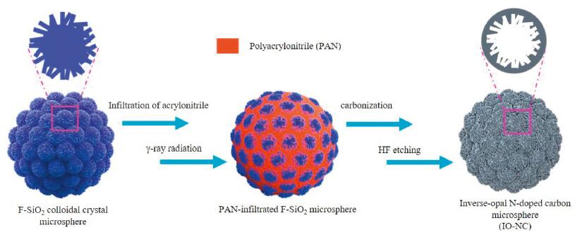
Based on the above successful preparation of F-SiO2 colloidal crystal microsphere template (Fig. S2b), micron-sized inverse-opal N-doped carbon (IO-NC) microspheres can be fabricated as illustrated in Fig. 2.

|
Download:
|
| Fig. 2. Schematic illustration of the preparation process of micron-sized IO-NC microspheres. | |
AN monomer is firstly infiltrated into the voids of the F-SiO2 colloidal crystal microspheres, and then in-situ polymerize initiated by γ-ray radiation to form PAN@F-SiO2 composite colloidal crystal microspheres. PAN can be commonly used as the carbon source containing N element [36]. Thus, after a carbonization process of calcination at 600 ℃ in argon and the following etching treatment in HF solution to remove F-SiO2 nanoparticles, self-standing IO-NC microspheres having a similar size to the F-SiO2 colloidal crystal microsphere template can be obtained, as shown in Fig. 3a. The enlarged SEM image of a part of external surface of a microsphere in Fig. 3a is shown in Fig. 3b. It can be seen that the carbon-based microspheres are constructed by the regularly stacking of nanoparticles with a size of about 330 nm, which is a little larger than the original F-SiO2 nanoparticles. Fig. 3c shows the enlarged cross section on a broken carbon-based microsphere in Fig. 3a. It shows clearly the inner pore structure of the carbon-based nanoparticle unit. As a whole, an inverse opal macroporous structure is clearly exhibited. However, the inner walls of each hollow carbon-based nanoparticles are filled with craters that look like fibers. Compared with the morphology of F-SiO2 nanoparticles in Fig. S1a, we can see that the inner hollow structure of the carbon-based nanoparticles in Fig. 3c is just the complementary structure of the removed F-SiO2 nanoparticles. The above results confirm that the carbon source PAN is mainly coated around each F-SiO2 nanoparticles on the colloidal crystal microsphere template so that IO-NC microspheres are fabricated after the carbonization and template etching processes.

|
Download:
|
| Fig. 3. (a) SEM image of IO-NC microspheres; the enlarged SEM images of (b) a part of the surface of a microsphere in (a), and (c) the cross section of a broken microsphere in (a). | |
The N2 adsorption-desorption isotherms of IO-NC microspheres shown in Fig. S3a (Supporting information) show a type IV curve with a typical H3 type hysteresis loop, which indicates that there exist meso-pores in IO-NC microspheres according to BDDT classification. The specific surface area of the microspheres is 266.4 m2/g. Analyzed by BJH method, the pore volume is 0.62 cm3/g and the most probable pore size is between 10~40 nm, as shown in Fig. S3b (Supporting information).
The XRD pattern of the IO-NC microspheres is shown in Fig. S4a (Supporting information). The microspheres show a broad diffraction peak at 20°~30°, superimposed with two peaks at around 26° and 44°, which could be attributed to the (002) and (100) crystal planes of graphite respectively. The result indicates that the matrix of the IO-NC microspheres is composed of amorphous and graphite carbon [37]. The TG curve of the microspheres is shown in Fig. S4b (Supporting information). A small mass loss before 100 ℃ is due to the evaporation of water and the sample decomposes completely at 500~750 ℃, indicating that silica template has been etched completely. According to the elemental analysis in Table S2, the IO-NC microspheres contain 15.04% of N element and 64.75% of C element, indicating a molar ratio of C/N of 5.0. The above results indicate micron-sized IO-NC microspheres with novel hierarchical macro-/meso-porous structure can be fabricated using the F-SiO2 colloidal crystal microsphere as the template and PAN as the carbon source.
IO-NC microspheres can be used as the absorbent for some small organic molecules. Thus, the adsorption performance of the IO-NC microspheres has been further investigated using RhB as the template molecule. As shown in Fig. S5 (Supporting information), when IO-NC microspheres are added into an aqueous solution of RhB at a concentration of 5 mg/L, the color of solution changes from rose to colorless within 12 h, indicating nearly all RhB molecules can be adsorbed by the IO-NC microspheres. The equilibrium adsorption capacity of the IO-NC microspheres reaches to 137.28 mg/(g microsphere) when the concentration of RhB is 100 mg/L. It can be summarized from the above results that micron-sized IO-NC microspheres have a good affinity and large capacity to small molecules.
In this work, F-SiO2 nanoparticles with an average diameter of 230 nm and a zeta potential of about −20 mV were prepared to fabricate micron-sized colloidal crystal microsphere template by water-evaporation-induced self-assembly in an inverse emulsion. AN was infiltrated in the voids of the F-SiO2 colloidal crystal microspheres, and in-situ polymerized into PAN by the initiation of 60Co γ-ray radiation. After the PAN-infiltrated F-SiO2 colloidal crystal microspheres were carbonized and etched with HF solution, novel micron-sized IO-NC microspheres consisting of hollow carbon nanoparticles with a hierarchical macro/meso-porous inner surface were obtained. The IO-NC microspheres have a specific surface area as high as 266.4 m2/g and a molar ratio of C/N of 5. They have a good dispersibility in water, and show a high adsorption capacity for RhB up to 137.28 mg/(g microsphere). Based on the hierarchical pore structure and the nitrogen doping composition, IO-NC microspheres also have the potential applications for the adsorption of volatile organic compounds (NH3, CO2) and heavy metal ions (Pb2+, Cu2+). This work offers a way to obtain novel micron-sized hierarchical macro-/meso-porous N-doped carbon microspheres, which can be expected to be used as high-performance carbon-based adsorption material.
Declaration of competing interestThe authors declare that they have no known competing financial interests or personal relationships that could have appeared to influence the work reported in this paper.
AcknowledgmentsThis work was supported by the National Natural Science Foundation of China (Nos. 51573174, 51773189 and 51973205), Science Challenge Project (No. TZ2018004) and the Fundamental Research Funds for the Central Universities (No. WK3450000004).
Appendix A. Supplementary dataSupplementary material related to this article can be found, in the online version, at doi:https://doi.org/10.1016/j.cclet.2020.06.004.
| [1] |
J. Lee, J. Kim, T. Hyeon, Adv. Mater. 18 (2006) 2073-2094. DOI:10.1002/adma.200501576 |
| [2] |
A. Stein, Z. Wang, M.A. Fierke, Adv. Mater. 21 (2009) 265-293. DOI:10.1002/adma.200801492 |
| [3] |
C. Vix-Guterl, E. Frackowiak, K. Jurewicz, et al., Carbon 43 (2005) 1293-1302. DOI:10.1016/j.carbon.2004.12.028 |
| [4] |
C.Z. Zhu, H. Li, S.F. Fu, D. Du, Y.H. Lin, Chem. Soc. Rev. 45 (2016) 517-531. DOI:10.1039/C5CS00670H |
| [5] |
W.K. Wang, Y.H. Wu, Z.W. Jiang, et al., Chin. Chem. Lett. 29 (2018) 931-934. DOI:10.1016/j.cclet.2017.11.003 |
| [6] |
Y.F. He, X.D. Zhuang, C.J. Lei, et al., Nano. Today 24 (2019) 103-119. DOI:10.1016/j.nantod.2018.12.004 |
| [7] |
C.D. Liang, Z.J. Li, S. Dai, Angew. Chem. Int. Ed. 47 (2008) 3696-3717. DOI:10.1002/anie.200702046 |
| [8] |
P. Selvam, B. Kuppan, Catal. Today 198 (2012) 85-91. DOI:10.1016/j.cattod.2012.06.033 |
| [9] |
M.R. Benzigar, S.N. Talapaneni, S. Joseph, et al., Chem. Soc. Rev. 47 (2018) 2680-2721. DOI:10.1039/C7CS00787F |
| [10] |
L. Liu, Q.F. Deng, B. Agula, et al., Catal. Today 186 (2012) 35-41. DOI:10.1016/j.cattod.2011.08.022 |
| [11] |
K.T. Lee, J.C. Lytle, N.S. Ergang, S.M. Oh, A. Steinet, Adv. Funct. Mater. 15 (2005) 547-556. DOI:10.1002/adfm.200400186 |
| [12] |
D.Y. Kang, S.O. Kim, Y.J. Chae, J.K. Lee, J.H. Moon, Langmuir 29 (2013) 1192-1198. DOI:10.1021/la304556w |
| [13] |
J.S. Yu, S. Kang, S.B. Yoon, G. Chai, J. Am. Chem. Soc. 124 (2002) 9382-9383. DOI:10.1021/ja0203972 |
| [14] |
L. Sun, H. Zhou, L. Li, et al., ACS Appl. Mater. Inter. 9 (2017) 26088-26095. DOI:10.1021/acsami.7b07877 |
| [15] |
L. Chuenchom, R. Kraehnert, B.M. Smarsly, Soft. Matter. 8 (2012) 10801-10812. DOI:10.1039/c2sm07448f |
| [16] |
X.Y. Xie, X.J. He, H.F. Zhang, et al., Chem. Eng. J. 350 (2018) 49-56. DOI:10.1016/j.cej.2018.05.011 |
| [17] |
Y.L. Wang, H.Q. Cui, Q.L. Zhao, X.M. Du, Matter 2 (2019) 626-638. |
| [18] |
J. Wang, Q.L. Zhao, H.Q. Cui, et al., J. Mater. Chem. A 6 (2018) 24748-24755. DOI:10.1039/C8TA04763D |
| [19] |
W.T. Huang, H. Zhang, Y.Q. Huang, W.K. Wang, S.C. Wei, Carbon 49 (2011) 838-843. DOI:10.1016/j.carbon.2010.10.025 |
| [20] |
S.B. Yoon, K. Sohn, J.Y. Kim, et al., Adv. Mater. 14 (2002) 19-21. |
| [21] |
B. Zhang, Cement. Concrete. Res. 28 (1998) 699-711. DOI:10.1016/S0008-8846(98)00037-4 |
| [22] |
J. Tang, J. Liu, R.R. Salunkhe, T. Wang, Y. Yamauchi, Chem. Commun. 52 (2016) 505-508. DOI:10.1039/C5CC07610B |
| [23] |
C.D. Liang, K.L. Hong, G.A. Guiochon, J.W. Mays, S. Dai, Angew. Chem. B 109 (2005) 20200-20206. |
| [24] |
Y.D. Xia, Z.X. Yang, R. Mokaya, Nanoscale 2 (2010) 639-659. DOI:10.1039/b9nr00207c |
| [25] |
H. Huang, J.M. Zhang, Y.X. Zhang, S.Y. Lian, Y. Liu, Solid. State. Sci. 24 (2013) 115-119. DOI:10.1016/j.solidstatesciences.2013.07.012 |
| [26] |
F.B. Su, X.S. Zhao, Y. Wang, et al., J. Phys. Chem. B 109 (2005) 20200-20206. DOI:10.1021/jp0541967 |
| [27] |
Y. Mao, H. Duan, B. Xu, et al., Energ. Environ. Sci. 5 (2012) 7950-7955. DOI:10.1039/c2ee21817h |
| [28] |
M.M. Li, F. Xu, H.R. Li, Y. Wang, Catal Sci Technol. 6 (2016) 3670-3693. DOI:10.1039/C6CY00544F |
| [29] |
J. Zhou, Z.S. Zhang, W. Xing, et al., Electrochimi. Acta 153 (2015) 68-75. DOI:10.1016/j.electacta.2014.11.075 |
| [30] |
Y.Y. Xie, W.X. Yang, M.Z. Wang, X.W. Ge, Chem. Eng. J. 323 (2017) 224-232. DOI:10.1016/j.cej.2017.04.035 |
| [31] |
Y.Y. Xie, J. Wang, M.Z. Wang, X.W. Ge, J. Hazard. Mater. 297 (2015) 66-73. DOI:10.1016/j.jhazmat.2015.04.069 |
| [32] |
S. Lei, J.X. Chen, K. Zeng, M.Z. Wang, X.W. Ge, Nano Res. 12 (2019) 1071-1082. DOI:10.1007/s12274-019-2348-1 |
| [33] |
W.X. Yang, K. Zeng, J.X. Liu, et al., J. Colloid. Interf. Sci. 548 (2019) 37-47. DOI:10.1016/j.jcis.2019.04.021 |
| [34] |
L.C. Chen, L.Z. Xie, M.Z. Wang, X.W. Ge, J. Mater. Chem. A 3 (2015) 2991-2998. DOI:10.1039/C4TA05898D |
| [35] |
N. Vogel, L.D. Viguerie, U. Jonas, C.K. Weiss, K. Landfester, Adv. Funct. Mater. 21 (2011) 3064-3073. DOI:10.1002/adfm.201100414 |
| [36] |
Y.F. Wang, L.H. Dong, R.L. Xiong, A.G. Hu, J. Mater. Chem. C 1 (2013) 7731-7735. DOI:10.1039/c3tc30949e |
| [37] |
S.Y. Tao, Y.C. Wang, D. Shi, et al., J. Mater. Chem. A 2 (2014) 12785-12791. DOI:10.1039/C4TA01909A |