 2021, Vol. 32


b Qilu University of Technology, Shandong Academy of Sciences, Ji'nan 250014, China
Electrochemical energy storage based on aqueous electrolytes is safer and more environmentally benign than that based on nonaqueous electrolytes. However, the major limitation of aqueous electrolytes is the intrinsically narrow potential window (1.23 V) of pure water, which limits the voltage and energy densities of aqueous batteries and impedes their commercialization [1, 2]. Considerable efforts have been devoted to widening the electrochemical potential windows of aqueous electrolytes to achieve high energy density [3-5].
An effective method of fabricating high-voltage aqueous electrolytes is by increasing the salt content of the aqueous electrolytes to a high concentration. Water-in-salt electrolytes (WISEs) have been successfully utilized in high-operating-voltage energy storage [6-11]. WISEs depend on salt concentration; when the salt concentration exceeds a high molar ratio, the water molecules become insufficient to form a classical primary solvation sheath. Moreover, the resultant WISE can be visualized as liquefied salt [12]. The most beneficial feature of WISE is the absence of free water molecules, thereby affording a widened electrochemical potential window [6, 12]. WISEs depend on the solubility of salts, such as the imide-based salt, in water [10, 13-15]. Thus, the electrochemical potential window of WISEs can be remarkably enhanced by the absence of free water molecules and the generation of a solid electrolyte interface (SEI) film due to the high concentration of Li-salt.
A eutectic system, consisting of LiTFSI or LiN(SO2C2F5)2 (LiBETI) salts can form a room-temperature (30 ℃) Li-salt monohydrate melt, with a concentration of 28 mol/kg, in which the water molecules are coordinated to a cation or anion in the absence of other free water molecules [13, 16]. The potential window can be further widened utilizing highly concentrated aqueous electrolytes with adequate SEI-forming ability. However, the Li-salt concentration has been limited to < 28 mol/kg despite many efforts by several groups to achieve higher concentrations [12-14, 16]. A feasible approach toward widening the potential window of electrolytes is the co-dissolution of salts to achieve highly concentrated electrolytes [13, 16, 17]. Particularly, Yamada's group reported a room-temperature (30 ℃) Li-salt monohydrate melt, as an approach toward achieving highly concentrated aqueous electrolytes (55.5 mol/kg). The monohydrate melt afforded a wide potential window of ~5 V, based on its improved passivation ability, which enabled the Li-alloying reaction of Al in aqueous electrolytes [18]. When the molar ratio of Li+ to water molecules in the electrolytes increased, the electrochemical potential window widened accordingly, from 21 mol/kg LiTFSI to 55 mol/kg Li(PTFSI)0.6(TFSI)0.4·H2O. The potential windows of these aqueous electrolytes exceeded the limitations of pure water by 3–5 V. However, highly concentrated electrolytes and soluble salts of many types, which are required in WISEs, are expensive. Moreover, the high concentration of a soluble salt, which exerts an adverse effect on the energy density, can ironically increase the density of the electrolytes. Therefore, randomly increasing the salt concentration cannot be overlooked as it can hinder the practical applications of WISEs.
In this study, we synthesized hydrous electrolytes, with improved electrochemical potential windows for water. Solid polyethylene glycol (PEG) and Li-salt were employed as the cosolutes. At room temperature (30 ℃), 1579 g of LiTFSI and 900 g of solid PEG2000 were dissolved in 100 g of water to form the hydrated electrolyte. First, PEG was dissolved in water to afford a PEG–water mixture, which was employed as a solvent for Li-salt. The cosolvation effect was employed to readily dissolve Li-ion in water since the ethylene oxide (EO) unit and the hydroxyl group (−OH) of PEG, which had been dissolved in water to afford a PEG–water mixture, can interact with Li-ion. The PEG–water mixture can achieve the high concentration of LiTFSI salt, required by the electrolytes, and results in high Li+ to H2O molar ratio. Moreover, the mole ratio of Li+ to water molecules in these hydrous electrolytes was approximately 1:1. The electrochemical stability of the electrolytes was considerably improved by the strong hydration of Li+ by water molecules. The mass fraction of LiTFSI salt, in these hydrous electrolytes, was remarkably reduced, compared to that in WISE. A Li4Ti5O12 (LTO) battery was tested in HMRE, and the results exhibited the environmental stability of the electrolyte. Furthermore, a low 1 C charge/discharge rate and ~100 mAh/g capacity could be achieved based on the LTO.
Preparation of HMRE: HMREs, composed of LiTFSI, deionized water, and PEG were prepared. First, calculated amounts of PEG2000 (J&K Scientific Ltd.) were placed in two 20 mL glass vials, after which calculated masses of deionized water were added. The mixtures were heated in a water bath to completely dissolve PEG2000 and form a homogeneous and transparent solution. Afterward, LiTFSI salt (Aladin Ltd.) was added, followed by heating and stirring, until the homogeneous and transparent electrolytes were formed.
Preparation of the LiMnO (LMO) cathode and LTO anode: LMO and nano-sized LiTO powders were purchased from MTI Corporation (Shenzhen). First, the active material powder, a polytetrafluoroethylene (PTFE) binder solution (60 wt% in water), and carbon black powder were mixed with ethanol until a homogenous slurry was formed. Thereafter, the slurry was transferred onto a C-coated Al foil, once ethanol had evaporated at room temperature (30 ℃), and hot-pressed. The resulting electrodes, with mass density per unit areas of 1–2 mg/cm2, containing 80 wt% active materials, 10 wt% PTFE, and 10 wt% carbon black, were utilized in all the electrochemical experiments.
Fabrication of the LTO battery: The LTO battery was assembled with the LMO cathode and LTO anode. A nonwoven fabric membrane (NKK-MPF30AC-100, NKK Corp., Japan) was employed as the separator. All the operations were conducted under the atmospheric conditions.
Electrochemical test: The cyclic voltammetry (CV) and linear sweep voltammetry (LSV) measurements were conducted on an electrochemical working station (CHI760E, Shanghai, China) with a three-electrode system, containing WISE (a saturated LiTFSI solution). A Hg/HgO electrode was employed as the reference electrode. The galvanostatic charge/discharge (GCD) tests were conducted with a CT-2001A multichannel battery tester (Wuhan Land Electronic Co., Ltd.).
Raman spectroscopy: the Raman spectra were obtained by a Horiba Jobin Yvon HR800 Raman spectrometer. The viscosities of the electrolytes were measured, using a capillary-gravity viscometer. The conductivity of the electrolyte was measured, using a DDBJ-351L conductivity meter (Shanghai REX Instrument Factory).
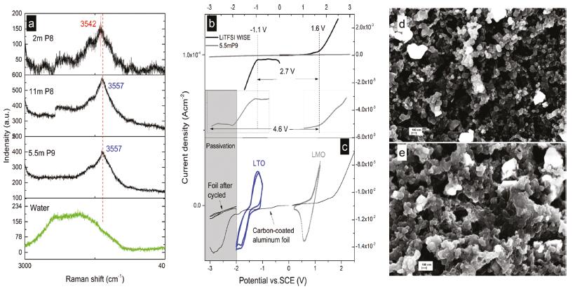
The properties and structures of the electrolytes were tested. As shown in Figs. 1a and b, 15.79 g of LiTFSI and 9 g of PEG2000 could be dissolved in 1 g of water to form the homogeneous and transparent electrolytes. The PEG–water solution, with a mass ratio of 9:1 (P9), was prepared for the experiments. At high temperature (> 30 ℃), both solutions formed the homogeneous and transparent electrolytes (Fig. 1c). Moreover, when the temperature was decreased to 20 ℃, the PEG–water solution began to solidify. However, WISEs were still liquid (Fig. 1d). The figure proves that the water molecules and LiTFSI could inhibit the crystallization of PEG and form a good system for cosolvation. The glue-like HMRE remained homogeneous and transparent (Fig. 1e) before they were taken out of the ice water bath. Additionally, the mixture exerted a cosolvation effect on LiTFSI. LiTFSI, in PEG, may increase the distance between the PEG molecules and reduce the crystallinity of PEG. Low- molecular-weight PEGs, such as PEG200, are −OH-rich and exhibit adverse electrochemical stabilities. Contrarily, high- molecular-weight PEGs, such as PEG6000, possess fewer −OH groups and exhibit better electrochemical stabilities. However, the solution is easily crystallized. Achieving high-salt content HMREs is challenging. Further, a molar ratio of Li+ to water, < 2:1, could be achieved. HMREs were annotated as xmPy; where xm is the molar concentration, based on the mass of PEG–water, and Py is the mass ratio of PEG to water. Different proportions of HMREs annotated 2mP8, 11mP8 and 5.5mP9 were prepared for this research.

|
Download:
|
| Fig. 1. Preparation of room-temperature (30 ℃) HMREs. (a) LiTFSI salt (0.056 mol), 9 g of PEG2000, and 1 g of water. (b) Stoichiometric amounts of LiTFSI, PEG, and water utilized to prepare a 5.5mP9 hydrate melt. (c) The electrolyte (5.5mP9) and P9 at 30 ℃. Both samples are in their liquid states. (d) The electrolyte (5.5mP9) and P9 at 20 ℃, the solidified P9 and liquid 5.5mP9. (e) The electrolyte (5.5mP9), which was immersed in an ice-water mixture, became a glue-like liquid at freezing point. | |
The compositions of the electrolytes are listed in Table S1 (Supporting information). In 5.5mP9, which has the lowest Li-salt content, the mass fraction of Li-salt could be reduced to 61%. Conversely, the mass fractions of Li-salts in 11mP8, WISE, and the monohydrate melt Li-salts were 76%, 86% and 95%, respectively. Further, 5.5mP9 possessed a high ratio of EO units and Li+ to water molecules. The mass fraction of Li-salt in 5.5mP9 was 70% of the classic WISE and 64% of the monohydrate Li melt. The high Li+ to water ratio electrolytes, fabricated by this method, could reduce the mass fraction of Li-salt along with the operating cost. The basic physical properties of the 5.5mP9 electrolyte, such as viscosity and ionic conductivity, are shown in the supporting information (Fig. S1 in Supporting information). We measured the conductivity and viscosity of the 5.5mP9 electrolyte in the temperature range of 55–30 ℃. The conductivity decreased from 0.22 mS/cm to 0.06 mS/cm because the viscosity had significantly increased (from 3013 mm2/S to 21, 358 mm2/S).
The structures of the electrolytes and water were studied by Raman spectroscopy (the corresponding Raman spectrum is shown in Fig. 2a). The O–H stretching vibration spectrum of pure water exhibited a broad Raman band, which was attributed to the various water molecules, with different hydrogen bonds in water [19]. However, the addition of LiTFSI salt and PEG (2mP8) resulted in a completely different observation; a new peak appeared at 3565 cm−1 (only a sharp peak without the broad band), indicating that abundant water had remarkably diminished in the extreme-state aqueous liquid. A sharp O–H vibration peak, which was characteristic of the crystalline hydrates and rarely observed in aqueous solutions, was observed [16, 18, 20, 21]. When the concentrations of LiTFSI salt and PEG increased, 11mP8 and 5.5mP9, which possessed the lowest water contents, exhibited sharp peaks at 3557 cm−1. Compared to 2mP8, the evident Raman shift in 5.5mP9 and 11mP8 are attributable to the strongest hydration of Li+ by the water molecules derived from the high molar ratios of Li+ to water therein.

|
Download:
|
| Fig. 2. (a) Raman spectra of the electrolytes. (b) LSV curves of the electrolytes in WISE and HMREs. Inset: details of the LSV of HMREs. (c) CV curves of the LTO and LMO electrodes and the C-coated Al foil in HMREs. (d, e) Morphologies of the C-coated Al foil before and after cycling. | |
The electrochemical performance of the electrolytes was characterized. The electrochemical window of the aqueous electrolytes was investigated by LSV. Fig. 2b shows the LSV curves of the electrolytes, which were tested on Pt working electrodes at scan rates of 1 (Fig. 2b inset) and 10 mV/s (Fig. 2b) versus a saturated calomel electrode (SCE), which was employed as a reference electrode. Contrarily, the LiTFSI-saturated aqueous electrolytes were also investigated under the same conditions. Resultantly, the LiTFSI-saturated aqueous electrolytes exhibited a widened potential window of 2.7 V, and 5.5mP9 exhibited almost the same potential but very low current. The aqueous electrolytes exhibited good performance in cathode materials, compared with in anode materials [22]. The performance of HMREs in anodes was tested by CV and LSV. The C-coated Al foil was employed as a current collector, and the LSV test was conducted at a low scan rate of 0.02 mV/s. Moreover, the decomposition potential could be reduced to −2 V vs. SCE. After CV, the current reduced and exerted the passivation effect after the decomposition of the electrolytes. This process could be utilized in the formation of SEI. Additionally, a wider potential window, ascribed to the passivation effect of SEI was observed. Moreover, the potential could be enhanced to 4.6 V [6, 18, 22, 23]. The CV curves of the LTO and LMO electrodes, in HMREs, are shown in Fig. 2c. A reversible redox pair was also observed and HMREs facilitated the reversible Li+ deintercalation/intercalation of the LTO and LMO electrodes. To prove the formation of the interphases, the electrodes were investigated by scanning electron microscopy (SEM) (Figs. 2d and e). Compared with the C-coated Al foil electrode without the CV cycle, evident coated layers could be observed on the surfaces of the electrodes. The SEM image with the LSV and CV results proves that SEIs, which protect the anode, could be formed in HMREs.
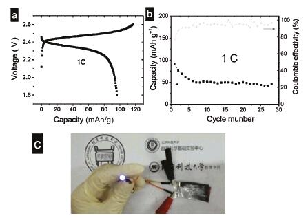
The performances of the electrolytes were tested in a full-cell. A 2.5 V cell, constructed with the LTO–LMO electrode, was assembled and evaluated in 5.5mP9 (Fig. 3a). The battery was operated by charge/discharge cycles. Thereafter, the capacity of the battery degraded evidently due to the bubbles from the decomposition of water in the electrolyte. In the first cycle, a low CE of 80% indicates that a relative amount of 5.5mP9 had been consumed to form SEI on the anode, along with some decomposition of water [22]. After several cycles, more electrolytes were added and the bubbles were squeezed out. Finally, the battery was sealed. A 1 C constant current rate was employed to demonstrate the authentic stability of HMREs at the electrode potentials. In the first cycle, the capacity of LTO attained ~100 mAh/g, which was like the performance of the Li-salt monohydrate melt. However, the mass fraction of Li-salt in HMREs was significantly reduced. The cycling stability and CE of the LTO–LMO full-cell, at various rates and voltages, are shown in Fig. 3b. In the first cycle, CE of 80% indicates the relative amounts of electrolytes, along with some water decompositions. Compared to the literature [18], the evident capacity decay may be due to the Al foil, utilized as a collector in the cathode. The precious metal, Ti, which exhibits good performance in the cathode [17, 18], was generally utilized as the collector in the cathode of aqueous electrolytes. HMREs have potentials for practical applications. Fig. 3c shows the image of 2.3 V blue LED bulbs lit with the LTO battery, in 5.5mP9.

|
Download:
|
| Fig. 3. (a) Typical voltage profiles of an LTO–LMO full-cell, at a constant current of 1 C (capacity and rate are dependent on the mass of the active material of the anode). (b) Cycling stability and coulombic efficiency (CE) of the LTO–LMO full-cell at 1 C. (c) Images of 2.3 V blue LED bulbs, lit with the LTO battery, in 5.5mP9. | |
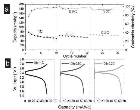
Low 0.2 and 0.5C rates were employed instead of high rates, to demonstrate the authentic stability of HMREs at the electrode potentials. The capacity and CE of the cell charge/discharge, at 0.2, 0.5 and 1 C are shown in Fig. 4a, the corresponding typical voltage profiles are shown in Fig. 4b, respectively. At a low operating rate, CE could of 90% be achieved, although the capacity was reduced after cycling. Note worthily, the capacity performance, in HMREs, was not very outstanding but this strategy can be employed to fabricate more similar HMREs. This work affords a new idea for the preparation of inexpensive and environmentally safe electrolytes.

|
Download:
|
| Fig. 4. (a) Cycling stability and CE of the LTO–LMO full-cell at various rates. (b) Typical voltage profiles of the LTO–LMO full-cell at constant current rates of 1, 0.5 and 0.2 C (capacity and rate are based on the mass of the active material of the negative electrode). | |
Summarily, we developed HMREs to achieve a high Li+ to water molar ratio while consuming less LiTFSI salt in the process and enabling a 2.5 V-class aqueous safe LTO battery. The hydration of Li+ by the cosolvation with the EO units of the PEG and water molecules, instead of by a single anion-water, avoided the random increase of Li-salts concentration when attempting to achieve a wide potential window, thus achieving cost-effectiveness. Moreover, the overall LiTFSI mass fraction was reduced to 61%, compared to WiSE (85%) or Li-salt monohydrate melts (95%), further overcoming the cost concern, imposed by LiTFSI. Based on this technical route, the development of an inexpensive electrolyte was beneficial. SEI could be formed and a wide electrochemical potential window (> 4.6 V) could be achieved.
Declaration of competing interestThe authors declare that they have no known competing financial interests or personal relationships that could have appeared to influence the work reported in this paper.
AcknowledgmentsThis work was supported by the National Natural Science Foundation of China (No. 11975043) and the Natural Science Foundation of Shandong Province (No. ZR2017LEM011).
Appendix A. Supplementary dataSupplementary material related to this article can be found, in the online version, at doi:https://doi.org/10.1016/j.cclet.2020.05.008.
| [1] |
H. Kim, J. Hong, K.Y. Park, et al., Chem. Rev. 114 (2014) 11788-11827. DOI:10.1021/cr500232y |
| [2] |
D. Bin, Y. Wen, Y. Wang, Y. Xia, J. Energy Chem. 27 (2018) 1521-1535. DOI:10.1016/j.jechem.2018.06.004 |
| [3] |
K.A. Owusu, Z. Wang, L. Qu, et al., Chin. Chem. Lett. 31 (2020) 1620-1624. DOI:10.1016/j.cclet.2019.09.045 |
| [4] |
D. Xie, F. Hu, X. Yu, et al., Chin. Chem. Lett. 31 (2020) 2268-2274. DOI:10.1016/j.cclet.2020.02.052 |
| [5] |
M. Yu, Y. Lu, H. Zheng, X. Lu, Chem. Eur. J. 24 (2018) 3639-3649. DOI:10.1002/chem.201704420 |
| [6] |
L. Suo, O. Borodin, T. Gao, et al., Science 350 (2015) 938-943. DOI:10.1126/science.aab1595 |
| [7] |
Q. Dou, S. Lei, D.W. Wang, et al., Energy Environ. Sci. 11 (2018) 3212-3219. DOI:10.1039/C8EE01040D |
| [8] |
H. Zhang, B. Qin, J. Han, S. Passerini, ACS Energy Lett. 3 (2018) 1769-1770. DOI:10.1021/acsenergylett.8b00919 |
| [9] |
L. Smith, B. Dunn, Science 350 (2015) 918. DOI:10.1126/science.aad5575 |
| [10] |
D.P. Leonard, Z. Wei, G. Chen, F. Du, X. Ji, ACS Energy Lett. 3 (2018) 373-374. DOI:10.1021/acsenergylett.8b00009 |
| [11] |
J. Yan, D. Zhu, Y. Lv, et al., Chin. Chem. Lett. 31 (2020) 579-582. DOI:10.1016/j.cclet.2019.05.035 |
| [12] |
L. Suo, O. Borodin, Y. Wang, et al., Adv. Energy Mater. 7 (2017) 1701189. |
| [13] |
L. Suo, O. Borodin, W. Sun, et al., Angew. Chem. Int. Ed. 55 (2016) 7136-7141. DOI:10.1002/anie.201602397 |
| [14] |
R.S. Kühnel, D. Reber, C. Battaglia, ACS Energy Lett. 2 (2017) 2005-2006. DOI:10.1021/acsenergylett.7b00623 |
| [15] |
Z. Tian, W. Deng, X. Wang, et al., Funct. Mater. Lett. 10 (2017) 1750081. DOI:10.1142/S1793604717500813 |
| [16] |
Y. Yamada, K. Usui, K. Sodeyama, et al., Nat. Energy 1 (2016) 16129. DOI:10.1038/nenergy.2016.129 |
| [17] |
M.R. Lukatskaya, J.I. Feldblyum, D.G. Mackanic, et al., Energy Environ. Sci. 11 (2018) 2876-2883. DOI:10.1039/C8EE00833G |
| [18] |
S. Ko, Y. Yamada, K. Miyazaki, et al., Electrochem. Commun. 104 (2019) 106488. DOI:10.1016/j.elecom.2019.106488 |
| [19] |
B. Auer, J. Skinner, J. Chem. Phys. 128 (2008) 224511. DOI:10.1063/1.2925258 |
| [20] |
V. Crupi, M. Jannelli, G. Maisano, et al., J. Mol. Struct. 381 (1996) 207-212. DOI:10.1016/0022-2860(96)09308-8 |
| [21] |
M. Kozielski, M. Mühle, Z. Błaszczak, J. Mol. Liquid. 111 (2004) 1-5. DOI:10.1016/j.molliq.2003.10.002 |
| [22] |
F. Wang, O. Borodin, M.S. Ding, et al., Joule 2 (2018) 927-937. DOI:10.1016/j.joule.2018.02.011 |
| [23] |
L. Suo, D. Oh, Y. Lin, et al., J. Am. Chem. Soc. 139 (2017) 18670-18680. DOI:10.1021/jacs.7b10688 |