 2021, Vol. 32


b Tianjin Key Laboratory of Molecular Optoelectronic Sciences, Department of Chemistry, School of Sciences, Tianjin University & Collaborative Innovation Center of Chemical Science and Engineering, Tianjin 300072, China;
c School of Physics and Electronics, Hunan University, Changsha 410082, China;
d Key Laboratory of Materials Processing and Mold (Zhengzhou University), Ministry of Education, Zhengzhou University, Zhengzhou 450002, China
Electrochemical oxygen reduction reaction (ORR) plays a crucial role in renewable energy storage and conversion systems such as fuel cells and metal-air batteries [1-4]. ORR process typically involves multiple proton-coupled electron transfer steps and suffers from sluggish reaction kinetics [5]. Therefore, active and durable electrocatalysts are highly desired to lower the reaction barrier and improve the reaction efficiency. Pt-based materials are still the state-of-the-art ORR electrocatalysts, but their disadvantages in terms of scarcity, high cost and poor stability greatly hinder the large-scale applications. Consequently, tremendous attention has been paid to active and stable nonprecious alternatives. Among the recently developed noble-metal-free electrocatalysts, transition metal/nitrogen-doped carbon (M-N-C) nanohybrids have emerged as the superior alternatives due to their low cost, comparable ORR activity and robust chemical stability [6-8]. In the nanohybrids, N atoms bond with C atoms forming diverse N configurations, and transition metals exist in the N-doped carbon matrix with enriched chemical valences. The interaction among transition metals, N species and carbon frameworks can delocalize the surface charge and promote the electron transfer, thus lead to a charge redistribution [9, 10]. As a result, the modified electric structures have been demonstrated to enhance the adsorption of O2 molecules, lower the reaction barrier, and synergistically facilitate the ORR process [11-13]. However, traditional synthetic methods for M-N-C (usually the pyrolysis of a simple mixture of transition metal salts and organic components [14-16]) generally result in nonuniform distribution and insufficient exposure of active sites, which limits the advances of M-N-C for boosting the ORR performance.
The emergence of metal-organic frameworks (MOFs), especially zeolitic imidazolate frameworks (ZIFs) with N-rich organic linkers, has recently provided sufficient platforms for fabricating M-N-C materials via pyrolysis route [2, 17]. Upon thermal treatment, atomically dispersed metal species in MOFs are in-situ transformed during the carbonization process of surrounded organic ligands. Meanwhile, the initial morphologies of MOFs precursors can be inherited by the resultant carbon matrixes under appropriate pyrolysis conditions. Thus, MOFs-derived strategies typically hold advantages in constructing M-N-C materials with uniformly distributed active sites and flexibly controllable dimensions. Nevertheless, the morphologies of nano/micro-MOFs are typically limited to polyhedral or irregular spherical shapes due to the fast growth kinetics of MOFs. For further engineering the architecture of MOFs-derived M-N-C materials, MOFs have been widely grown/composited with 1D carbon nanotubes [18, 19] and 2D graphene [20, 21]/layered double hydroxide (LDH) nanosheets [22, 23]. Among the constructed architectures, carbon nanotube arrays grown on 2D substrates have been reported to be capable for improving the electrocatalytic performance [24, 25]. On one hand, the carbon nanotube arrays with high specific surface area can enhance the exposure of active sites and electrical conductivity. Meanwhile, as the ORR process occurs at the solid-liquid-gas (i.e., electrode-electrolyte-O2) triple-phase interface, carbon nanotube arrays with multiscale channels can provide sufficient triple-phase interface to synergistically facilitate the ORR process [26]. On the other hand, the interstitial spaces between adjacent 2D substrates act as 2D channels for further enhancing the mass transport for both liquid and gaseous intermediates. Such routes, however, usually require the introduction of extra templates and involve complex multiple steps. In addition, controllable architecture engineering on MOFs composites is always restricted by the involved multiple components with different properties.
Herein, we report the construction of cobalt embedded N-doped carbon nanotube arrays on 2D MOFs-derived nanosheets (Co/NCNTs/NSs) via the pyrolysis of Co/Zn-MOF nanosheets. After thermal treatment, the Co/NCNTs/NSs well inherit the 2D structure feature of Co/Zn-MOF nanosheets. Meanwhile, Co-encapsulated N-doped carbon nanotubes (Co/NCNTs) are in-situ grafted on the surface of nanosheets resulted from the Co-catalyzed carbonization process. The composite is confirmed to contain enriched N configurations, especially a high relative content of Co-Nx after nitridation treatment. The resultant hierarchical structure with 0D/1D Co/NCNTs interface and 1D (nanotubes)/2D (nanosheets) junction is expected to construct open and connective channels, as well as conductive networks to achieve highly exposed active sites, enhanced mass transport and improved charge transfer. As a result, the Co/NCNTs/NSs exhibit excellent activity and stability towards ORR in both alkaline and acidic media, benefiting from the synergy of active component and advanced structure. The strategy developed in this work is believed versatile for fabricating other MOFs-derived materials with hierarchical structures and diverse applications in energy-related systems.
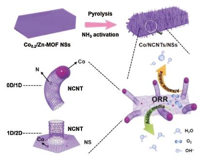
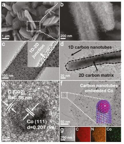
The synthetic procedure of Co/NCNTs/NSs is schematically illustrated in Fig. 1. With the aim of constructing a carbon matrix with 2D overall framework, Co/Zn-MOF nanosheets composed of Co2+, Zn2+metal sites and 2-methylimidazole organic linkers are chosen as the precursor. Generally, Zn-MOF (ZIF-8) rhombic dodecahedrons (Fig. S1a in Supporting information) are obtained through the coordination of Zn2+ and 2-methylimidazole in methanol media. In our case, Zn-MOF nanosheets (Fig. S1b in Supporting information) can be successfully prepared in aqueous solution [27]. Different from the cubic structure of Zn-MOF rhombic dodecahedrons (Fig. S1c in Supporting information), the Zn-MOF nanosheets possess a monoclinic crystalline phase (Fig. S1d in Supporting information) [27]. The monoclinic and cubic structures are the polymorphs of ZIF-8 which have been reported previously [28, 29]. The difference in the crystalline structures is reported to arise from the different symmetries between the involved water and methanol molecules in the synthetic procedures. According to the experimental and simulated PXRD patterns in Figs. S1c and d, the monoclinic Zn-MOF NSs and cubic ZIF-8 NPs both show high purity. When Co2+ ions are involved in the synthetic procedure, Co/Zn-MOFs containing different Co/Zn molar ratios from 0.1 to 0.4 (determined by inductively coupled plasma mass spectrometer (ICP-MS) results in Table S1, denoted as Co0.1, 0.2, 0.3, 0.4/Zn-MOF) with retained morphology of nanosheets (Figs. S2a–d in Supporting information) and structure of monoclinic phase (Fig. S2e in Supporting information) can be obtained. The observed color change from white to hyacinth of the products clearly indicates the incorporation of Co2+ ions. Finally, the Co/NCNTs/NSs are synthesized via the pyrolysis of Co/Zn-MOF nanosheets in H2/Ar atmosphere then in NH3/Ar gas. Fig. 2a shows the typical scanning electron microscopy (SEM) image of the Co/NCNTs/NSs prepared through the calcination of Co/Zn-MOF nanosheets with a Co/Zn molar ratio of 0.2 at 800 ℃ in H2/Ar atmosphere followed by treatment at 350 ℃ in NH3/Ar atmosphere. After thermal treatment, the 2D morphology of Co/Zn-MOF nanosheets is well retained, while the surface of the Co/NCNTs/NSs becomes rough. The magnified SEM image with a side view of the Co/NCNTs/NSs in Fig. 2b confirms the formation of carbon nanotube (CNT) arrays and indicates the inside-to-outside growth direction of the CNTs along the surface of the nanosheets. As shown by the transition electron microscopy (TEM) images in Figs. 2c and d, CNTs with a diameter around 5 nm grow uniformly surrounding the surface of the Co/NCNTs/NSs. The in-situ grown 1D CNTs are covalently linked with the 2D nanosheets, which can form 1D/2D junction for enhancing the electron transfer throughout the structure. Co nanoparticles are observed to be uniformly embedded in the carbon matrix. The embedded Co nanoparticles are encapsulated by a few layers of graphitic carbon with an inter-plane distance of 0.36 nm (Fig. 2e). Compared with the ideal graphite that has a corresponding distance of 0.34 nm [30, 31], the present graphitic carbon exhibits an expanded interlayer distance which has also been observed in other reported carbon materials [32-34]. The high-resolution TEM (HRTEM) image clearly shows the crystalline lattice with an interplanar spacing of 0.205 nm, which is in good agreement with the (111) plane of face-centered cubic (fcc) Co. Co nanoparticles are also observed inside the tips of CNTs forming 0D/1D Co/CNTs interface (Fig. 2f), which indicates the metal nanocrystals catalyzed formation process of CNTs [35]. The distribution of Co nanoparticles throughout the Co/NCNTs/NSs is further confirmed by the high-angle annular dark-field scanning transmission electron microscopy (HAAD-STEM) image in Fig. 2g. The corresponding elemental mapping reveals the uniform distribution of Co, N and C elements in the composite. These results clearly demonstrate the formation of Co/N-doped carbon nanotubes arrays grown on 2D carbon matrix in the resultant Co/NCNTs/NSs.

|
Download:
|
| Fig. 1. Schematic illustration of the synthetic procedure of Co/NCNTs/NSs. | |

|
Download:
|
| Fig. 2. (a) SEM image of the as-prepared Co/NCNTs/NSs and (b) high-magnified SEM image of the part marked by a dotted box in a. (c) TEM image of Co/NCNTs/NSs with an enlarged view (inset) of the 1D (nanotubes)/2D (nanosheets) junction. (d) TEM image with a side view of the Co/NCNTs/NSs. HRTEM images of (e) graphitic layers coated Co nanoparticle and (f) Co nanoparticles wrapped inside the tips of carbon nanotubes. (g) STEM and elemental mapping images showing the uniform distribution of C (red), N (yellow) and Co (green). | |
The carbon nanotube arrays are confirmed to form in the first-step pyrolysis in the H2/Ar atmosphere. As shown in Fig. S3c (Supporting information), uniformly grown carbon nanotubes can already be observed on the surface of carbonized nanosheets (derived from Co0.2/Zn-MOF nanosheets) before the nitridation treatment. During the thermal treatment in the H2/Ar atmosphere, cobalt ions are firstly reduced into metallic Co that nucleate and grow to tiny nanocrystals. Then, organic residuals acting as the carbon source grow into carbon nanotubes, which are catalyzed by the in-situ formed Co nanocatalysts. When Zn-MOF nanosheets without Co incorporation were used as the precursor, only carbonized nanosheets with porous surface were obtained (Fig. S3e in Supporting information). With the use of Co0.1/Zn-MOF nanosheets precursor containing a low amount of Co, none of the carbon nanotubes could be observed (Fig. S3d in Supporting information) due to the lack of Co nanocatalysts. As the Co/Zn molar ratios increase to 0.3 and 0.4 in the Co/Zn-MOF precursors, the TEM images in Figs. S3a and b (Supporting information) clearly show the formation of carbon nanotubes after thermal treatment in H2/Ar atmosphere. However, in comparison with the products (Fig. S3c) prepared from Co0.2/Zn-MOF nanosheets, the sizes of embedded Co nanoparticles obviously become larger due to the sintering of Co species under the relatively high content. These results indicate the critical role of in-situ formed Co nanocrystals for catalyzing the growth of carbon nanotubes, which has been widely confirmed in previous reports [35-37]. Moreover, an optimized amount of incorporated Co is benefit for the construction of hierarchical structures with tiny embedded Co nanoparticles. The effect of first-step calcination temperature on the composites derived from Co0.2/Zn-MOF nanosheets was also investigated and shown in Fig. S4 (Supporting information). At a low temperature of 700 ℃, tiny Co nanoparticles were observed throughout the nanosheets, while only a few short carbon nanotubes appeared on the surface (Fig. S4a). The incomplete pyrolysis of Co0.2/Zn-MOFs under such a low temperature mainly leads to the insufficient growth of carbon nanotubes. As the temperatures increased to 900 ℃ and 1000 ℃, enhanced pyrolysis promoted the catalytic growth of longer carbon nanotubes, while the Co nanoparticles also grew into larger sizes (Figs. S4c and d). As a result, a Co/Zn molar ratio of 0.2 and a pyrolysis temperature of 800 ℃ were set as the optimized conditions in the first-step thermal treatment. For comparison, Co0.2/Zn-MOF rhombic dodecahedrons with the size of ~250 nm were also synthesized in methanol media for the use as a precursor (Fig. S5a in Supporting information). After the same first-step treatment, only rhombic dodecahedrons with embedded Co nanoparticles were obtained (Figs. S5b and c in Supporting information), further indicating the advantages of the Co0.2/Zn-MOF nanosheets for the construction of hierarchical structure. The compositions and structures of the series of Co/N doped carbon nanosheets (denoted as Cox/NC/NSs-y; x=0.1, 0.2, 0.3 and 0.4, notes the Co/Zn molar ratio in the precursors; y=700, 800, 900 and 1000, notes the first-step pyrolysis temperature) were firstly identified and compared via X-ray diffraction (XRD) measurements. As exhibited in Fig. S6 (Supporting information), no diffraction peaks belonging to metal Zn are observed due to the evaporation of low boiling point Zn [38, 39]. Co0.1/NC/NSs-800 solely give the signals of the carbonaceous component, which is consistent with the observed lack of Co nanocatalysts. All the other samples present the components of metallic Co and carbon. When the pyrolysis temperature is fixed, the intensity of the peaks of metallic Co obviously increases with the increase of Co amount. In the case with constant Co/Zn molar ratio in the precursors, the degree of graphitization shows gradual enhancement with the increase in calcination temperature. The contents of N atoms in the carbon matrixes are confirmed by the results of element analysis in Table S2 (Supporting information). The X-ray photoelectron spectroscopy (XPS) spectra for N 1s of the Cox/NC/NSs-y reveal the types of N species in each sample. All the N 1s spectra can be fitted into four peaks corresponding to pyridinic N, Co-Nx, pyrrolic N and graphitic N (Fig. S7a and b in Supporting information). Fig. S8 and Table S3 (Supporting information) summaries the relative content of each type of N species in the samples. Notably, the Co0.2/NC/NSs-800 possess a high relative content of Co-Nx (20.57%) which is confirmed to be the critical active center for ORR [40]. The Co 2p spectrum of Co0.2/NC/NSs-800 (Fig. S7c in Supporting information) can be deconvoluted into three characteristic peaks of Co° (778.6 eV), Co2+ (781.8 eV) and Co3+ (780.3 eV) [41-43]. Moreover, the Brunauer–Emmett–Teller (BET) calculations from N2 sorption isotherms curves assign the largest specific surface area of 685.2 m2/g to the Co0.2/NC/NSs-800 (Fig. S9 and Table S4 in Supporting information). The Co0.2/NC/NSs-800 with well-defined hierarchical structure, uniformly dispersed Co nanoparticles, high content of Co-Nx and the largest specific surface area is thus chosen as the optimized precursor for nitridation treatment to investigate the composition and electrocatalytic performance of the resultant Co/NCNTs/NSs.
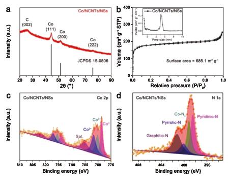
The XRD pattern of the Co/NCNTs/NSs in Fig. 3a exhibits four diffraction peaks. The peak locating at 26° belongs to the (002) plane of graphitic carbon. The other three peaks at 44.2°, 51.5° and 75.9° correspond to the (111), (200) and (222) planes of metallic Co with a fcc structure (PDF No. 150806). The structure of the carbon matrix is further verified by Raman spectrum. Fig. S10 (Supporting information) clearly shows the characteristic D-bond (1340.7 cm−1) and G-bond (1584.5 cm−1) that are ascribed to the graphitic sp2-carbon and disordered/defect carbon, respectively. The intensity ratio of G- and D-bond (IG/ID) with a value of 0.95 indicates the presence of rich disordered or defect carbon, which is expected to facilitate the improvement of electrocatalytic performance. Element analysis confirms the variation of N content in the composites before (Co0.2/NC/NSs-800) and after (Co/NCNTs/NSs) nitridation treatment. Obviously, the N content increases from 8.61 wt% in Co0.2/NC/NSs-800 to 11.67 wt% in Co/NCNTs/NSs (Table S2).

|
Download:
|
| Fig. 3. (a) Powder XRD pattern, (b) N2 sorption isotherms (the inset shows the pore size distribution), (c) Co 2p and (d) N 1s XPS spectra of Co/NCNTs/NSs. | |
As no diffraction belonging to cobalt nitride is detected by the XRD result, the increased N content mainly derives from the surface nitridation of Co nanoparticles and the N doping in the carbon matrix. In general, MOFs-derived carbon matrixes possess diverse porous structures that are benefit to expose active sites and enhance mass transfer in the catalytic process. To investigate the porous structure of Co/NCNTs/NSs, N2 sorption measurement is conducted at 77K. Fig. 3b shows the characteristic type-I isotherms [11, 44]. The corresponding pore size distribution is present in the inset. Typically, at low relative pressure, a sharp increase in the volume indicates the existence of micropores with a pore size less than 1 nm. The hysteresis loop confirms the coexistence of mesopores (5 nm) at high relative pressure between 0.4 and 0.9. The hierarchical porous structure gives a large specific surface area of 685.16 m2/g to Co/NCNTs/NSs according to BET calculations. In order to investigate the chemical composition and electronic states of the Co/NCNTs/NSs, XPS was performed. The full survey spectrum in Fig. S11a (Supporting information) reveals the coexistence of Co, C, N and O elements in the composite. The high-resolution Co 2p spectrum (Fig. 3c) exhibits three types of Co valence including Co0 (778.6 eV), Co2+ (781.7 eV) and Co3+ (780.2 eV) [45]. The C 1s core-level spectrum (Fig. S11b in Supporting information) can be fitted into three peaks at 284.8, 285.4, and 288.9 eV which are ascribed to C-C, C=N and O-C=O, respectively [46]. It has been demonstrated that the C=N can modify the electronic structures of nearby metal/carbon atoms and thus provide more active sites for ORR. Meanwhile, the charge redistribution on carbon atoms upon N doping is confirmed to benefit the adsorption of O2 [47]. The N 1s spectrum in Fig. 3d can be deconvoluted into four peaks, corresponding to pyridinic N, Co-Nx, pyrrolic N and graphitic N with binding energies at 398.5 eV, 399.1 eV, 400.1 eV and 401.5 eV, respectively [44, 48]. Fig. S12 and Table S3 (Supporting information) compares the relative contents of each type of N species in Co0.2/NC/NSs-800 and Co/NCNTs/NSs. In comparison with Co0.2/NC/NSs-800, the relative content of pyridinic N in Co/NCNTs/NSs has a slight increase, while an obvious increase of 11.45% is confirmed for graphitic N. Both pyridinic N and graphitic N are reported to be beneficial for ORR [49]. Notably, the relative content of Co-Nx, which is confirmed to be the crucial active site for electrochemical O2 reduction, increases from 20.57% in Co0.2/NC/NSs-800 to 26.07% in Co/NCNTs/NSs. Thus, upon nitridation treatment, the variation of relative contents for different N species is expected to boost the electrocatalytic performance of Co/NCNTs/NSs composite further.
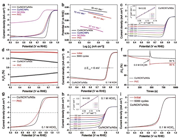
The ORR performance of a series of Cox/NC/NSs-y prepared via annealing Co/Zn-MOF nanosheets in the H2/Ar atmosphere was first measured under identical conditions. It is found that the Co0.2/NC/NSs-800 shows superior ORR performance (Fig. S13 and Table S5 in Supporting information), which has been predicted by their above- confirmed optimized structure, high content of Co-Nx species and large surface area. M-N-C materials have been widely demonstrated to be capable of boosting the ORR performance [31, 50]. In our case, the high content of Co-Nx species is believed to play a critical role in boosting the ORR performance. Upon the charge transfer among the Co, N and C, the O2 molecules chemisorption mode could be changed and the cleavage of O=O bond would be facilitated. In addition, the redistributed charge density could also alter the adsorption/desorption of intermediates (e.g., OOH*, O* and OH*) and reaction pathways. As a result, the reaction barrier of ORR is effectively decreased and the reaction kinetics is improved. The result confirms the reliability of selecting Co0.2/NC/NSs-800 as the typical precursor for post-nitridation treatment to boost the advantages of Co/NCNTs/NSs for ORR. The electrocatalytic activity of Co/NCNTs/NSs towards ORR was first evaluated by cyclic voltammogram (CV) tests in N2 or O2-saturated 0.1 mol/L KOH solution. The obvious cathodic peak locating at 0.87 VRHE (the subscript "RHE" notes that the potential is converted to reversible hydrogen electrode potential) in O2-saturated KOH solution whereas absent in N2-saturated KOH (Fig. S14 in Supporting information) indicates the activity of Co/NCNTs/NSs for electrochemically reducing O2 molecules. The nearly rectangular shape of the CV curve suggests that the Co/NCNTs/NSs are highly conductive and enriched in active sites on the surface [51]. Linear scan voltammogram (LSV) curve of the Co/NCNTs/NSs was tested at a rotating speed of 1600rpm in O2-saturated KOH solution. As shown in Fig. 4a, the Co/NCNTs/NSs possess a high onset potential (0.96 VRHE), half-wave potential (0.87 VRHE) and large limiting current density of 5.12 mA/cm2. The onset potential and half-wave potential are higher than those of Co0.2/NC/NSs-800 (0.93 VRHE and 0.85 VRHE) and even higher than those of Pt/C (0.95 VRHE and 0.83 VRHE), and the limiting current density is comparable to 5.47 mA/cm2 of Pt/C. To identify the advantages of Co/NCNTs/NSs for electrocatalytically reducing oxygen, the ORR performance of Co/NC/NPs and NC/NSs (synthesized by using Co0.2Zn-MOF rhombic dodecahedrons and Zn-MOF nanosheets as precursors under the same annealing conditions, respectively) was measured under identical conditions. In comparison with Co/NCNTs/NSs, both Co/NC/NPs and NC/NSs show negative onset potentials (0.94 VRHE and 0.84 VRHE) and half-wave potentials (0.84 VRHE and 0.74 VRHE) in Fig. 4a, which indicates the higher activity of Co/NCNTs/NSs. The Tafel plots in Fig. 4b derived from polarization curves also demonstrate the superior catalytic performance of the composite. The Co/NCNTs/NSs exhibits the smallest slope of 50 mV/dec, while Co/NC/NPs and NC/NSs show larger slopes of 70 and 87 mV/dec, respectively. The smallest slope of Co/NCNTs/NSs suggests its most favorable ORR kinetics.

|
Download:
|
| Fig. 4. (a) LSV curves at a rotation rate of 1600 rpm and (b) Tafel plots of the Co/NCNTs/NSs, Co/NC/NPs, NC/NSs and Pt/C in O2-saturated 0.1 mol/L KOH. (c) RDE polarization curves of Co/NCNTs/NSs at different rotation rates (400-2500 rpm). The inset shows the K-L plots of Co/NCNTs/NSs at different potentials. (d) Electron transfer number (n, upside) and H2O2 yield (downside) of Co/NCNTs/NSs and Pt/C. (e) ORR polarization curves (at 1600 rpm) of the Co/NCNTs/NSs before and after 5000 cycles. (f) Methanol tolerance test for Co/NCNTs/NSs and Pt/C at 0.6 VRHE in O2-saturated 0.1 mol/L KOH solution at 1600 rpm. (g) LSV curves at a rotation rate of 1600 rpm of the Co/NCNTs/NSs and Pt/C in O2-saturated 0.1 mol/L HClO4. (h) RDE polarization curves of Co/NCNTs/NSs at different rotation rates (400-2500 rpm). The inset shows the K-L plots of Co/NCNTs/NSs at different potentials. (i) ORR polarization curves (at 1600 rpm) of the Co/NCNTs/NSs before and after 5000 cycles in O2-saturated 0.1 mol/L HClO4. | |
According to Koutechy-Levich (K-L) equation, the electron transfer number per oxygen molecule (n) and kinetic limiting current density (JK) of Co/NCNTs/NSs, Co/NC/NPs and NC/NSs for ORR were calculated from LSV curves obtained under different rotating speeds (Fig. 4c and Fig. S15 in Supporting information). As shown in Fig. 4c, the K-L plots of Co/NCNTs/NSs exhibit good linearity in the range of 0.4 to 0.7 VRHE, indicating a first-order reaction kinetics for ORR. The calculated electron transfer number around 3.93 confirms a Pt/C-like four-electron oxygen reduction reaction with the formation of OH– in alkaline electrolyte. The four-electron pathway of Co/NCNTs/NSs for ORR is also demonstrated by the result of an H2O2 yield below 7% with n=3.88–3.92 in the potential range of 0.3−0.8 VRHE, which were obtained via rotation ring-disk electrode test (Fig. 4d). In sharp contrast, the NC/NSs show a mixed two or four-electron oxygen reduction process with n ≈ 2.63 (Fig. S15b), and the n for Co/NC/NPs is around 3.70 (Fig. S15d). The JK based on the geometric area of the electrode (0.196 cm−2) for Co/NCNTs/NSs at 0.85 VRHE is calculated to be 13.83 mA/cm2, which is higher than 3.67 and 0.02 mA/cm2 for Co/NC/NPs and NC/NSs, respectively. The comparison of the half-wave potential (E1/2) and JK among Co/NCNTs/NSs, Co/NC/NPs, NC/NSs and Pt/C in Fig. S16 (Supporting information) confirms the superior ORR performance of Co/NCNTs/NSs. Moreover, the performance of Co/NCNTs/NSs outperforms most previously reported Co-N-C carbon-based materials (Table S6 in Supporting information).With superior activity towards ORR, the Co/NCNTs/NSs also exhibit excellent durability in long-term cycling tests and high methanol tolerance. As shown in Fig. 4e, the half-wave potential of Co/NCNTs/NSs only negatively shifts 6 mV after 5000 CV sweeps. However, a negative shift of 20 mV is observed for Pt/C (Fig. S17a in Supporting information). During the chronoamperometric measurement at 0.6 VRHE, the catalytic current density of Co/NCNTs/NSs can return to 95% of the initial value after a rapid injection of methanol, while an 85% remained current is observed for Pt/C (Fig. 4f). Meanwhile, when 0.5 mol/L methanol is introduced in 0.1 mol/L KOH solution, both the position and strength of oxygen reaction peak for Co/NCNTs/NSs keep the same, indicating a high resistance to methanol poisoning (Fig. S17b in Supporting information).
The superior ORR performance of Co/NCNTs/NSs is suggested to derive from the advantages in terms of chemical composition and unique structure via the comparison with Co/NC/NPs and NC/NSs. For M-N-C electrocatalysts, the incorporated transition metal and nitrogen species in the carbon matrix both play crucial roles in improving the ORR performance. In comparison with NC/NSs without Co, the presence of Co species in Co/NCNTs/NSs and Co/NC/NPs cannot only enhance the electrical conductivity through catalyzing the graphitization of the carbon matrix but also form highly active Co-Nx sites towards ORR. Additionally, the electron interaction between the cobalt nanoparticles and a few layers of graphite coating can modify the binding strength of intermediates [11] on the surface of Co/NCNTs/NSs and Co/NC/NPs, also enhancing the ORR performance. Thus, both Co/NCNTs/NSs and Co/NC/NPs show higher ORR activity than that of NC/NSs. According to the analysis of N 1s spectra, the Co/NCNTs/NSs and Co/NC/NPs possess comparable sum of relative contents of pyridinic N, Co-Nx and graphitic N as summarized in Fig. S18 and Table S3 (Supporting information). Nevertheless, the electrocatalytic activity of Co/NCNTs/NSs is superior to that of Co/NC/NPs. The unique structure of Co/NCNTs/NSs is thus believed reasonable to its higher catalytic activity. The high-density Co/N doped carbon nanotube arrays with 0D/1D Co/NCNTs interface can effectively increase the accessible surface area and enhance the exposure of N-C/Cox-N active sites. On the other hand, the in-situ grown 1D carbon nanotubes on the surface of 2D carbon matrix can form 1D/2D junctions as connective channels to enhance electron transfer for further improving the ORR performance. The favorable electron transfer of Co/NCNTs/NSs during the ORR process is indicated by the lower charge transfer resistance confirmed by the smaller semicircle [52-54] in the Nyquist plots (Fig. S19 in Supporting information) compared with Co0.2/NC/NSs-800. Also, the interstitial spaces between adjacent Co/NCNTs/NSs can form 2D channels to enhance the mass transport of both liquid and gaseous reactants, ensuring a high reaction efficiency for ORR [55]. The small Tafel slope of Co/NCNTs/NSs (50 mV/dec) has confirmed the positive effect of the structure on the ORR process. Meanwhile, the advantages of the hierarchical structure are also demonstrated by the results of electrochemical double layer capacitance (Cdl) that represents the electrochemical surface area (ECSA). As shown in Fig. S20 (Supporting information), Co/NCNTs/NSs exhibits much higher Cdl of 45.3 mF/cm2 than 18.3 mF/cm2 of Co/NC/NPs. Therefore, the unique structure of Co/NCNTs/NSs with 0D/1D Co/NCNTs interface and 1D/2D junction plays a crucial role in improving the ORR performance.
For commercial applications in proton exchange membrane fuel cells (PEMFCs), the ORR performance of a catalyst in acidic media is of great significance. Thus, the ORR performance of Co/NCNTs/NSs was further investigated in 0.1 mol/L HClO4 solution. As shown in Fig. 4g, the onset potential of Co/NCNTs/NSs is 40 mV lower than 0.92 VRHE of Pt/C, while the half-wave potential of Co/NCNTs/NSs (0.78 VRHE) is comparable to that of Pt/C (0.77 VRHE) and better than many reported M-N-C based carbon composites (Table S7 in Supporting information). Meanwhile, a well-defined diffusion-limiting current density of 5.91 mA/cm2 is observed after a mixed kinetic-diffusion region. The smaller Tafel slope of Co/NCNTs/NSs (74 mV/dec) than that of Pt/C (81 mV/dec) further indicates the favorable ORR kinetics of the composite (Fig. S21a in Supporting information). In acidic media, the first-order reaction kinetics with respect to the O2 reactant and four-electron ORR process are well remained as demonstrated by the K-L plots with good linearity and n ≈ 4.0 in Figs. 4h and d. An H2O2 yield below 1.5% and high n from 3.96 to 3.97 observed in Fig. S21b (Supporting information) also confirm the efficient ORR process. Remarkably, the Co/NCNTs/NSs show better durability than that of Pt/C in 0.1 mol/L HClO4. After 5000 continuous CV sweeps, the Co/NCNTs/NSs exhibits a negligible negative shift of half-wave potential (Fig. 4i), whereas the half-wave potential of Pt/C negatively shifts 27 mV. Besides, the Co/NCNTs/NSs also display stronger resistance to methanol poisoning compared with Pt/C (Fig. S21c in Supporting information). The relative current of the Co/NCNTs/NSs changes less and recovers back to 95% quickly after the injection of methanol, while a great decline of the current density of Pt/C occurs. The excellent ORR performance of Co/NCNTs/NSs in acidic media holds great promise for their applications in PEMFCs.
In summary, Co/N-doped carbon nanotube arrays grown on 2D MOFs-derived matrix have been successfully constructed via the pyrolysis of bimetallic Co/Zn-MOF nanosheets. The Co/Zn-MOF nanosheets endow the 2D carbonized framework morphology to the Co/NCNTs/NSs and provide C and N source for in-situ growth of 1D carbon nanotubes on the surface of 2D nanosheets. The resultant Co/NCNTs/NSs with abundant active Co-Nx sites and hierarchal structure possess highly exposed active surface, enhanced mass transport and improved charge transfer. As a result, the Co/NCNTs/NSs exhibit excellent ORR performance with an E1/2 of 0.87 VRHE and a JK of 13.83 mA/cm2 at 0.85 VRHE in alkaline media, which are superior to those of commercial Pt/C and most Co-N-C electrocatalysts. Impressively, the Co/NCNTs/NSs also display comparable activity (E1/2 = 0.78 VRHE) and even better stability towards ORR in acidic media than those of Pt/C. The present strategy here is expected to inspire the construction of many other MOFs-derived hierarchical structures and pave the development of high-performance materials for the applications in energy storage and conversion systems.
Declaration of competing interestThe authors declare that they have no known competing financial interests or personal relationships that could have appeared to influence the work reported in this paper.
AcknowledgmentsThis work was supported by the National Natural Science Foundation of China (NSFC, Nos. 21701124 and 51702236), Tianjin Municipal Science and Technology Commission (Nos. 18TCQNJC71500 and 17JCZDJC38000) and the National Key R&D Program of China (No. 2017YFA0700104).
Appendix A. Supplementary dataSupplementary material related to this article can be found, in the online version, at doi:https://doi.org/10.1016/j.cclet.2020.04.040.
| [1] |
Z.P. Cano, D. Banham, S. Ye, et al., Nat. Energy 3 (2018) 279-289. DOI:10.1038/s41560-018-0108-1 |
| [2] |
L. Yang, X. Zeng, W. Wang, D. Cao, Adv. Funct. Mater. 28 (2018) 1704537. DOI:10.1002/adfm.201704537 |
| [3] |
Y.J. Wang, H. Fan, A. Ignaszak, et al., Chem. Eng. J. 348 (2018) 416-437. DOI:10.1016/j.cej.2018.04.208 |
| [4] |
Y.J. Wang, B. Fang, D. Zhang, et al., Electrochem. Energy Rev. 1 (2018) 1-34. DOI:10.1007/s41918-018-0002-3 |
| [5] |
Z.W. Seh, J. Kibsgaard, C.F. Dickens, et al., Science 355 (2017) 146. |
| [6] |
C. Zhu, H. Li, S. Fu, D. Du, Y. Lin, Chem. Soc. Rev. 45 (2016) 517-531. DOI:10.1039/C5CS00670H |
| [7] |
H.F. Wang, C. Tang, Q. Zhang, Adv. Funct. Mater. 28 (2018) 1803329. DOI:10.1002/adfm.201803329 |
| [8] |
G. Wu, A. Santandreu, W. Kellogg, et al., Nano Energy 29 (2016) 83-110. DOI:10.1016/j.nanoen.2015.12.032 |
| [9] |
B. You, N. Jiang, M. Sheng, et al., ACS Catal. 5 (2015) 7068-7076. DOI:10.1021/acscatal.5b02325 |
| [10] |
H. Sung, M. Sharma, J. Jang, et al., Nanoscale 11 (2019) 5038-5047. DOI:10.1039/C8NR10327E |
| [11] |
S. Liu, Z. Wang, S. Zhou, et al., Adv. Mater. 29 (2017) 1700874. DOI:10.1002/adma.201700874 |
| [12] |
K. Artyushkova, I. Matanovic, B. Halevi, P. Atanassov, J. Phys. Chem. C 121 (2017) 2836-2843. DOI:10.1021/acs.jpcc.6b11721 |
| [13] |
K. Zhao, S. Liu, G. Ye, et al., ChemSusChem 13 (2020) 1556-1567. DOI:10.1002/cssc.201902776 |
| [14] |
J.Y. Choi, R.S. Hsu, Z. Chen, J. Phys. Chem. C 114 (2010) 8048-8053. DOI:10.1021/jp910138x |
| [15] |
H. Peng, F. Liu, X. Liu, et al., ACS Catal. 4 (2014) 3797-3805. DOI:10.1021/cs500744x |
| [16] |
K. Lee, L. Zhang, H. Lui, et al., Electrochim. Acta 54 (2009) 4704-4711. DOI:10.1016/j.electacta.2009.03.081 |
| [17] |
N. Cheng, L. Ren, X. Xu, Y. Du, S.X. Dou, Adv. Energy Mater. 8 (2018) 1801257. DOI:10.1002/aenm.201801257 |
| [18] |
Y. Liu, G. Li, Y. Guo, Y. Ying, X. Peng, ACS Appl. Mater. Interfaces 9 (2017) 14043-14050. DOI:10.1021/acsami.7b03368 |
| [19] |
H. Zhang, X. Li, A. Hähnel, et al., Adv. Funct. Mater. 28 (2018) 1706847. DOI:10.1002/adfm.201706847 |
| [20] |
H.X. Zhong, J. Wang, Y.W. Zhang, et al., Angew. Chem. Int. Ed. 53 (2014) 14235-14239. DOI:10.1002/anie.201408990 |
| [21] |
J. Wei, Y. Hu, Y. Liang, et al., Adv. Funct. Mater. 25 (2015) 5768-5777. DOI:10.1002/adfm.201502311 |
| [22] |
Z. Li, M. Shao, L. Zhou, et al., Nano Energy 25 (2016) 100-109. DOI:10.1016/j.nanoen.2016.04.041 |
| [23] |
Y. Qian, T. An, E. Sarnello, et al., ACS Appl. Energy Mater. 2 (2019) 1784-1792. DOI:10.1021/acsaem.8b01923 |
| [24] |
V. Vij, J.N. Tiwari, K.S. Kim, ACS Appl. Mater. Interfaces 8 (2016) 16045-16052. DOI:10.1021/acsami.6b03546 |
| [25] |
Z. Chen, R. Wu, Y. Liu, et al., Adv. Mater. 30 (2018) 1802011. DOI:10.1002/adma.201802011 |
| [26] |
Y. Wang, Y. Zou, L. Tao, et al., Nano Res. 12 (2019) 2055-2066. DOI:10.1007/s12274-019-2310-2 |
| [27] |
Y. Jiang, H. Liu, X. Tan, et al., ACS Appl. Mater. Interfaces 9 (2017) 25239-25249. DOI:10.1021/acsami.7b04432 |
| [28] |
A.D. Katsenis, A. Puškarić, V. Štrukil, et al., Nat. Commun. 6 (2015) 6662-6669. DOI:10.1038/ncomms7662 |
| [29] |
Y. Jiang, H. Liu, X. Tan, et al., ACS Appl. Mater. Interfaces 9 (2017) 25239-25249. DOI:10.1021/acsami.7b04432 |
| [30] |
R. Ma, X. Ren, B.Y. Xia, et al., Nano Res. 9 (2016) 808-819. DOI:10.1007/s12274-015-0960-2 |
| [31] |
R. Ma, G. Lin, Y. Zhou, et al., NPJ Comput. Mater. 5 (2019) 1-15. DOI:10.1038/s41524-018-0138-z |
| [32] |
B.Y. Xia, Y. Yan, N. Li, et al., Nat. Energy 1 (2016) 1-8. |
| [33] |
J. Meng, C. Niu, L. Xu, et al., J. Am. Chem. Soc. 139 (2017) 8212-8221. DOI:10.1021/jacs.7b01942 |
| [34] |
W. Yang, W. Yang, F. Zhang, G. Wang, G. Shao, Small 14 (2018) 1802221. DOI:10.1002/smll.201802221 |
| [35] |
J. Meng, C. Niu, L. Xu, et al., J. Am. Chem. Soc. 139 (2017) 8212-8221. DOI:10.1021/jacs.7b01942 |
| [36] |
B.Y. Xia, Y. Yan, N. Li, H.B. Wu, X.W. Lou, et al., Nat. Energy 1 (2016) 15006. DOI:10.1038/nenergy.2015.6 |
| [37] |
S. Wang, J. Qin, T. Meng, M. Cao, Nano Energy 39 (2017) 626-638. DOI:10.1016/j.nanoen.2017.07.043 |
| [38] |
Z. Li, M. Shao, L. Zhou, et al., Nano Energy 25 (2016) 100-109. DOI:10.1016/j.nanoen.2016.04.041 |
| [39] |
P. Yin, T. Yao, Y. Wu, et al., Angew. Chem. Int. Ed. 55 (2016) 10800-10805. DOI:10.1002/anie.201604802 |
| [40] |
C. Tang, B. Wang, H.F. Wang, Q. Zhang, Adv. Mater. 29 (2017) 1703185. DOI:10.1002/adma.201703185 |
| [41] |
Q. Liang, Z. Chen, X. Chen, Y. Li, J. Mater. Chem. A 7 (2019) 20310-20316. DOI:10.1039/C9TA07481C |
| [42] |
Y. Shi, Y. Wang, Y. Yu, Z. Niu, B. Zhang, J. Mater. Chem. A 5 (2017) 8897-8902. DOI:10.1039/C7TA02838E |
| [43] |
Z. Wei, J. Wang, S. Mao, et al., ACS Catal. 5 (2015) 4783-4789. DOI:10.1021/acscatal.5b00737 |
| [44] |
Y. Li, B. Jia, Y. Fan, et al., Adv. Energy Mater. 8 (2018) 1702048. DOI:10.1002/aenm.201702048 |
| [45] |
Q. Liang, Z. Chen, X. Chen, Y. Li, J. Mater. Chem. A 7 (2019) 20310-20316. DOI:10.1039/C9TA07481C |
| [46] |
H. Ning, G. Li, Y. Chen, et al., ACS Appl. Mater. Interfaces 11 (2018) 1957-1968. |
| [47] |
W.J. Jiang, L. Gu, L. Li, et al., J. Am. Chem. Soc. 138 (2016) 3570-3578. DOI:10.1021/jacs.6b00757 |
| [48] |
X. Song, L. Guo, X. Liao, et al., Small 13 (2017) 1700238. DOI:10.1002/smll.201700238 |
| [49] |
L. Lai, J.R. Potts, D. Zhan, et al., Energy Environ. Sci. 5 (2012) 7936-7942. DOI:10.1039/c2ee21802j |
| [50] |
R. Ma, G. Lin, Q. Ju, et al., Appl. Catal. B 265 (2020) 118593. DOI:10.1016/j.apcatb.2020.118593 |
| [51] |
S.H. Ahn, A. Manthiram, Small 13 (2017) 1603437. DOI:10.1002/smll.201603437 |
| [52] |
Y. Zhang, Y. Hu, S. Li, J. Sun, B. Hou, J. Power Sources 196 (2011) 9284-9289. DOI:10.1016/j.jpowsour.2011.07.069 |
| [53] |
B. Li, Z. He, M. Wang, X. Wang, Int. J. Hydrogen Energy 42 (2017) 5261-5271. DOI:10.1016/j.ijhydene.2017.01.087 |
| [54] |
Y. Sun, Y. Duan, L. Hao, et al., ACS Appl. Mater. Interfaces 8 (2016) 25923-25932. DOI:10.1021/acsami.6b06895 |
| [55] |
X. Chia, M. Pumera, Nat. Catal. 1 (2018) 909-921. DOI:10.1038/s41929-018-0181-7 |