 2021, Vol. 32


Since its discovery, metal organic frameworks (MOFs) have attracted tremendous attraction because of their fascinating properties, such as porous nanostructure and high surface area [1]. As there are growing application of MOFs to many areas such as gas storage/separation [2], catalysis [3], sensing [4] and waste disposal [5], the fast and scale-up synthesis of MOFs has always been an important issue [6]. In past decades, many artist methods such as conventional electric heating [7], microwave heating [8], electrochemistry [9], mechanochemistry [10] and ultrasonic method [11], have been employed for MOFs synthesis. Among the different synthesis strategy, the electrochemistry seems to have potential application in scale-up fast production [7]. As early as 2005, BASF firstly created the electrochemistry synthesis methods achieving ability of production HKUST-1 by 5.1 g with about 6.4 g A−1 h−1 current efficiency [12]. From that time, many literatures have modified the electrochemistry synthesis method [9, 13, 14], however the current efficiency has no significant advance. Fast and energy efficient synthetic method is still highly required.
Microplasma electrochemistry has attracted increasing attention, especially in the field of materials synthesis [15-17]. The charge transfers and plasma neutral reactions at the plasma-liquid interface provide a unique environment for chemical reactions [18-20]. Compared with the conventional solid electrode, the microplasma has three special characters: (ⅰ) As a kind of electrode, microplasma could carry the charges into solution and induce electrochemical reactions in a controllable manner; (ⅱ) Microplasma is a gas-state electrode which means the electrode interface is real-time renewable and the electrolysis product would not attach on its surface; (ⅲ) There are plenty of gaseous high energy species in the plasma that could induce plasmachemical reaction. Up to now, most of the reports on the application of microplasma are focused on the preparation of metal nanoparticles, by utilizing the first two properties, electron transfer and renewable interface.
Recently, our group has expanded the application of microplasma to accelerating the synthesis of organic nanomaterials at room temperature by utilizing all three characters, and we name this microplasma electrochemistry based method as MIPEC strategy. It is found that the microplasma anode could accelerate the condensation reaction of citric acid and ethanediamine to form fluorescent carbon nanodots, while either platinum anode or the microplasma cathode could not induce the reaction [21]. Another example is the application of MIPEC on accelerating the polymerization of dopamine. The microplasma cathode could provide OH- from electrolysis of water and species with oxidative activity from plasma-chemical reaction, both of which could induce the polymerization of dopamine. The synergistic effect result in one of the fastest polymerization method [22]. While on the microplasma anode, fluorescent polydopamine nanoparticles could be obtained due to the co-existence of inductive effect of species with oxidative activity as well as inhibition effect of H+ from electrolysis [23]. These works have shown the potential of MIPEC for its application in materials synthesis.
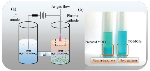
Herein, we developed a microplasma electrochemistry (MIPEC) strategy for fast and controllable synthesis of MOFs. HKUST-1, one of the most commonly used MOFs, was selected as the model MOF for testing the MIPEC method. Briefly, Cu(NO3)2 and 1, 3, 5-benzenetricarboxylic acid were dissolved in N, N-dimethylformamide (DMF) and transferred into an 'H' type reaction equipment (Fig. 1a). The precursor solution was treated with microplasma cathode for 15 min with a discharge current of 10 mA. Plenty of blue precipitate was obtained in the reaction solution, while, for comparison, there was very little product if only standing for more than 3 months (Fig. 1b).

|
Download:
|
| Fig. 1. (a) Schematic of preparing HKUST-1 with the atmospheric-pressure microplasma cathode electrode and Pt anode electrode. (b) Left: Precursor solution treated with microplasma at 10 mA for 15 min. Right: Precursor solution without treatment after 3 months. | |
The obtained product (experiment details in Supporting information) was first analysed with powder X-ray diffraction (XRD) (Fig. 2a). The experimental pattern fitted well with the reported pattern of HKUST-1 [24], confirming the formation of HKUST-1. No obvious noise peaks were detected, indicating no other impure crystals were synthesized in the reaction. The HKUST-1 crystals could also be seen on the scanning electron microscope (SEM) images (Fig. 2b). The specific pore volume and surface area of the products were determined by nitrogen physisorption after washing with ethanol. The prepared HKUST-1 had shown a specific surface area as high as 673 m2/g. The presence of a hysteresis loop at relative high pressure in the nitrogen adsorption/desorption analysis indicated the existence of mesoporous structures. The calculated average mesoporous diameter by Barrett-Joyner-Halenda method (BJH) method was about 1.8 nm and mesopore distribution was in a wide range (Fig. 2c). The thermal analysis of HKUST-1 had shown apparently two weight losses stage (Fig. 2d). The weight loss at first stage was about 100 ℃, which was ascribed to the departure of the water or the ethanol inside the pore. The second one started at about 300 ℃, relating to the decomposition of the trimesic acid. These results suggested that HKUST-1 was successfully prepared by the MIPEC method.

|
Download:
|
| Fig. 2. Characterization of HKUST-1 prepared by microplasma. (a) Powder XRD pattern. (b) SEM image. (c) Nitrogen physisorption curve. (d) Thermogravimetric analysis. | |
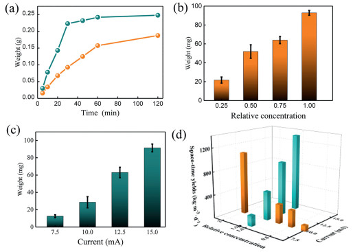
To understand the growth process of the HKUST-1 with the MIPEC method, the influence of discharge time, current and raw materials concentration were studied. Firstly, a HKUST-1 precursor solution at 2 N concentration (precursor concentration prepared by dissolving Cu(NO3)2·3H2O (2.44 g) and 1, 3, 5-benzenetricarboxylic acid (1.16 g) in DMF (100 mL) was defined as 1 N concentration) was treated by the microplasma cathode with different discharge time. As shown in Fig. 3a, the weight of prepared HKUST-1 increased linearly with reaction time within 30 min and then achieved an equilibrium state. For a lower concentration (1 N), a similar trend was obtained but it needed a longer time (60 min) to achieve the equilibrium state. The results showed that, with the same discharge current, a higher raw materials concentration could result in a faster production rate. It was also noticed that the production rate become a little bit slower with the increase of time, which might be caused by the decreasing of raw materials concentrations along with reaction process. To figure that out, four different raw materials concentrations, 0.25 N, 0.5 N, 0.75 N and 1 N, were chosen and the discharge time was shortened to 30 min to give less influence on the concentration change within the whole reaction time. The results showed that more products could be obtained with a higher raw materials concentration (Fig. 3b). Then, the precursor solution at 1 N concentration was treated by microplasma cathode with different discharge currents and the same discharge time (10 min). As expected, higher discharge currents resulted in more product (Fig. 3c). These results above indicated that the MIPEC method could be used for fast synthesis of HKUST-1 and the production rate could be adjusted by the discharge current and raw materials concentration.

|
Download:
|
| Fig. 3. (a) Relationship between collected MOFs weight and time when microplasma as cathode and Pt as anode. The yellow line means the 1 normalized concentration and the green line means 2 normalized concentration. (b) The relationship between production weight of MOFs and raw materials solution concentration with a constant current of 10 mA. (c) The relationship between production weight and discharge current when the raw materials concentration kept same. (d) The space-time yield of MOFs with MIPEC method at different raw materials concentration and discharge current. | |
To compare the production speed and efficiency at different reaction conditions, according to the literatures, space-time yield was defined and calculated as follow.

|
As shown in Fig. 3d, with the same discharge current at 10 mA, the space-time yield increased with the raw materials concentration from 96 kg m-3 d-1 (at 0.25 N concentration) to 1070 kg m-3 d-1 (at 2 N concentration). While with the same raw materials concentration (1 N), the obtaining space-time yield increased with current from 178 kg m-3 d-1 (at 7.5 mA) to 1326 kg m-3 d-1 (at 15 mA). This space-time yield of this MIPEC method is much higher than that of commonly used solvent thermal method, which is usually below 300 kg m-3 d-1. By increasing the discharge current and raw materials concentration and coupling this method with flow synthesis, space-time yield could be further improved for practical application.
The MIPEC method has two advantages than conventional electrochemical method. Firstly, the MIPEC method has much higher current efficiency than conventional electrochemical method, in which generation of OH- on the cathode would cause ligand deprotonation and induce the MOFs nucleation and growth process. Supposing all the prepared MOFs were induced by the electrochemical effect, when the current was 10 mA for 30 min, the calculated weight of MOFs should be 0.036 g, while it was much less than the actual production weight (0.23 g) by MIPEC method (Supporting information). The calculated current efficiency of MIPEC is about 46 g A-1 h-1, which is about 7 times current efficiency of electrochemistry method. Secondly, different from that in the conventional method the growth of MOFs directly occurred on the solid electrode surface, the prepared MOFs with the MIPEC method would precipitate and leave away from the plasmasolution reaction interface in a relative short time, making MIPEC has potential for continuous production with flow synthesis.
In view of the high space-time yield and higher current efficiency, we assume the synthesis process was mainly attributed by the integrated MIPEC impact, which means electrochemical affect (deprotonation mainly induced by the free electrons in the microplasma) and neutral reaction (mainly induced by the high energy species in the microplasma) both attribute to the synthesis process of MOFs.
In our hypothesis, the whole MOFs synthesis process is considered to compose of two steps: Nucleation and growth. When the microplasma was ignited, the plasma would bring plenty of free electrons and high energy species to the interface between plasma and solution, inducing the activation of ligands and metal ions for polymerization and resulting in a rapid nucleation process in this area (Fig. 4a). The formed nucleuses and activated raw materials then diffused to the diffusion area for further growth. Once away from the nucleation and diffusion area, without enough activated raw materials, the growth process was ended and the MOFs nanoparticles would sediment to the bottom. The hypothesis was testified by the size distribution of prepared MOFs. As the nucleation process mainly happening in the nucleation area and the grown process mainly happening in the diffusion area, larger discharge currents could induce more nucleuses without increasing the particles size (Fig. 4b). While a higher concentration of raw materials in the diffusion area would result in more adequately growth of the particles and a larger size (Fig. 4c).

|
Download:
|
| Fig. 4. (a) Illustration of synthesis process induced by MIPECT impact, the red area means the nucleation area, the yellow area means the diffusion area and the blue area means the bulk solution. Relationship between size distribution of prepared MOFs and (b) discharge current, and (c) solution concentration. | |
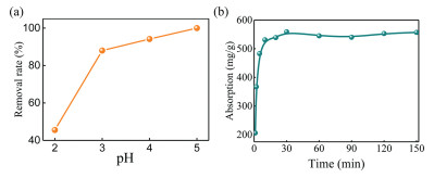
The MIPEC prepared MOFs were further employed for rapid adsorption of uranium in aqueous solution to test their properties. Uranium is a valuable raw material for nuclear power plants as well as a toxic radioactive element, it is crucial to develop a simple method for the rapid adsorption of uranium in the waste water produced during the mining and processing progress [25]. To avoid the impact from pH, pH 4 was chosen for adsorption experiment (Fig. 5a). As shown in Fig. 5b, the uptake amount of U(Ⅵ) increased sharply in a few minutes. After about 10 min, the adsorption process reached equilibration, and the adsorption capacity could be as much as 550 mg/g, suggesting an ultrafast adsorption kinetics and high adsorption capacity of HKUST-1.

|
Download:
|
| Fig. 5. (a) Impact of initial pH on uranium adsorption. Co(U) = 100 mg/L, Cadsorbent = 0.25 g/L and time = 120 min. (b) Effect of contact time on the U(Ⅵ) adsorption property of the HKUST-1 adsorbent. Co(U) = 100 mg/L, Cadsorbent = 0.25 g/L and pH = 4. | |
To sum up, a microplasma electrochemistry (MIPEC) strategy was developed to accelerate the synthesis process of MOFs with microplasma acting as cathode. The strategy provides a potential alternative for fast scale-up production of MOFs, achieving a high space-time yield and high current efficiency. The obtained MOFs showed similar excellent uranium adsorption properties compared to those obtained by other method. Especially, inspired by this work and our group's former papers about accelerating synthesis process of organic materials, the new strategy also may offer a choice for accelerating conventional organic materials synthesis. Future efforts would be focused on studying the mechanism of the method, expanding production scale, and extending the method to more MOFs.
Declaration of competing interestThe authors declare that they have no known competing financial interests or personal relationships that could have appeared to influence the work reported in this paper.
AcknowledgmentWe acknowledge the National Natural Science Foundation of China (Nos. 21976104 and 21775087).
Appendix A. Supplementary dataSupplementary data associated with this article can be found, in the online version, at https://doi.org/10.1016/j.cclet.2020.04.019.
| [1] |
P. Falcaro, R. Ricco, C.M. Doherty, et al., Chem. Soc. Rev. 43 (2014) 5513-5560. DOI:10.1039/C4CS00089G |
| [2] |
J. Fu, S. Das, G. Xing, et al., J. Am. Chem. Soc. 138 (2016) 7673-7680. DOI:10.1021/jacs.6b03348 |
| [3] |
K.M. Choi, D. Kim, B. Rungtaweevoranit, et al., J. Am. Chem. Soc. 139 (2017) 356-362. DOI:10.1021/jacs.6b11027 |
| [4] |
H. Liu, H. Wang, T. Chu, et al., J. Mater. Chem. C: Mater. Opt. Electron. Devices 2 (2014) 8683-8690. DOI:10.1039/C4TC01551G |
| [5] |
L. Zhu, D. Sheng, C. Xu, et al., J. Am. Chem. Soc. 39 (2017) 14873-14876. |
| [6] |
A.U. Czaja, N. Trukhan, U. Muller, Chem. Soc. Rev. 38 (2009) 1284-1293. DOI:10.1039/b804680h |
| [7] |
N. Stock, S. Biswas, Chem. Rev. 112 (2012) 933-969. DOI:10.1021/cr200304e |
| [8] |
S.H. Jhung, J.H. Lee, J.W. Yoon, et al., Adv. Mater. 19 (2007) 121-124. DOI:10.1002/adma.200601604 |
| [9] |
M. Li, M. Dinca, J. Am. Chem. Soc. 133 (2011) 12926-12929. DOI:10.1021/ja2041546 |
| [10] |
P.A. Julien, K. Uzarevic, A.D. Katsenis, et al., J. Am. Chem. Soc. 138 (2016) 2929-2932. DOI:10.1021/jacs.5b13038 |
| [11] |
W.J. Son, J. Kim, J. Kim, et al., Chem. Commun. 47 (2008) 6336-6338. |
| [12] |
U. Mueller, M. Schubert, F. Teich, et al., J. Mater. Chem. 16 (2006) 626-636. DOI:10.1039/B511962F |
| [13] |
M. Li, M. Dinca, Chem. Sci. 5 (2014) 107-111. DOI:10.1039/C3SC51815A |
| [14] |
R. Ameloot, L. Stappers, J. Fransaer, et al., Chem. Mater. 21 (2009) 2580-2582. DOI:10.1021/cm900069f |
| [15] |
G. Saito, T. Akiyama, J. Nanomater. 2015 (2015) 1-21. |
| [16] |
L. Lin, Q. Wang, Plasma Chem. Plasma Process. 35 (2015) 925-962. DOI:10.1007/s11090-015-9640-y |
| [17] |
T. Yan, X. Zhong, A.E. Rider, et al., Chem. Comm. 50 (2014) 3144-3147. DOI:10.1039/C3CC48846B |
| [18] |
C. Richmonds, M. Witzke, B. Bartling, et al., J. Am. Chem. Soc. 133 (2011) 17582-17585. DOI:10.1021/ja207547b |
| [19] |
P. Rumbach, M. Witzke, R.M. Sankaran, et al., J. Am. Chem. Soc. 135 (2013) 16264-16267. DOI:10.1021/ja407149y |
| [20] |
P. Rumbach, D.M. Bartels, R.M. Sankaran, et al., Nat. Commun. 6 (2015) 1-7. |
| [21] |
Z. Wang, Y. Lu, H. Yuan, et al., Nanoscale 7 (2015) 20743-20748. DOI:10.1039/C5NR05804J |
| [22] |
Z. Wang, C. Xu, Y.X. Lu, et al., Poly. Chem. 8 (2017) 4388-4392. DOI:10.1039/C7PY00805H |
| [23] |
Z. Wang, Y.X. Lu, G.Y. Wei, et al., J. Chem. Eng. 344 (2018) 480-486. DOI:10.1016/j.cej.2018.03.096 |
| [24] |
R. Ameloot, E. Gobechiya, H. Uji-i, et al., Adv. Mater. 22 (2010) 2685-2688. DOI:10.1002/adma.200903867 |
| [25] |
M. Carboni, C.W. Abney, S. Liu, et al., Chem. Sci. 4 (2013) 2396-2402. DOI:10.1039/c3sc50230a |