 2021, Vol. 32


b Beijing Advanced Innovation Centre for Soft Matter Science and Engineering, Beijing University of Chemical Technology, Beijing 100029, China
Lithium-ion batteries (LIBs), based on their high energy density, long lifespan and environmental benignity, are widely dominant among various energy storage systems [1-3]. However, the limited lithium resources restrict their future large-scale applications in electric vehicles and power grids [4]. Here, sodium-ion batteries (SIBs) are gaining substantial attention as a promising substitute for LIBs based on the vast abundance and affordable cost of sodium resources [5-7]. Despite the promising performance, the use of commercial graphite anode in SIBs suffers from sluggish reaction kinetics due to poor Na-ion insertion ability compared to small-radii Li-ions [7, 8]. Thus, the development of an engineered anode with stable kinetics is a necessity before SIBs could be advanced for the commercial market.
The SnO2, based on its alloying/dealloying sodium storage mechanism, is considered a promising anode material for SIBs with a theoretical capacity reach of 1369 mAh/g [9, 10]. However, the low electrical conductivity and sizeable volume variations during charge-discharge cycles limit its practical applicability in SIBs [11-13]. Among the efficient solution, the integration of SnO2 with conductive materials, e.g., carbon [14] and graphene [15], configured as hybrid composite has proven effective in improving the inherent electrochemical characteristics of SnO2. For example, Qin et al. integrated SnO2 with carbon in a sandwiched configuration to construct C@SnO2@C hollow nanostructures. The presence of carbon as shell and core substantially improved cycling stability and rate capability of C@SnO2@C-based anode in SIBs [16].
In this study, we propose a unique pomegranate-like SnO2/reduced graphene oxide (rGO)/Se composite spheres, i.e., p-SnO2/rGO/Se, as an efficient anode material for SIBs. The p-SnO2/rGO/Se spheres were fabricated using simple one-pot spray pyrolysis of a mixture containing SnCl2, graphene oxide (GO) and SeO2. The pyrolytic conversion of SeO2 into Se in the presence of rGO constructed a pomegranate-like rGO architecture that could support fast charge-transfer besides alleviating the large volume changes of SnO2. The unique architectures enabled improved sodium storage performance with a capacitive reach of 506.7 mAh/g at 30 mA/g, a cycle performance of 397 mAh/g after 100 cycles at 50 mA/g, and a rate performance of 188.9 mAh/g at 10 A/g.
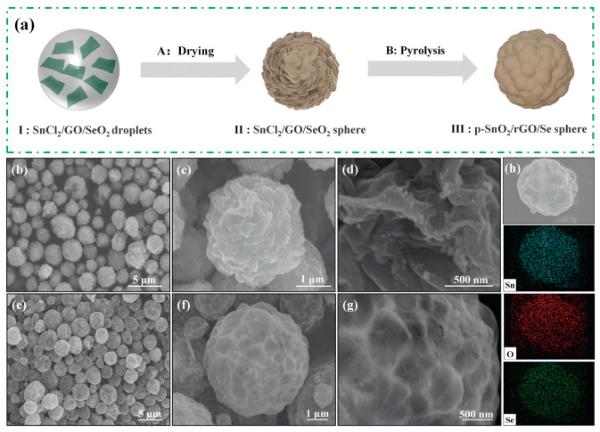
The facile synthesis of the p-SnO2/rGO/Se spheres using the spray pyrolysis method is illustrated in Fig. 1a and Fig. S1 (Supporting information). The mixed solution of SnCl2, GO and SeO2 was treated in an ultrasonic bath to atomize the large droplets into a fine aerosol. This aerosol, when entered a quartz tube, maintained at 800 ℃, immediately dried, resulting in the formation of SnCl2/GO/SeO2 composite spheres. Then the composite spheres passed through the pyrolytic region, SnCl2 decomposed into SnO2, and thermal reduction of GO to rGO was occurred at the high temperature of 800 ℃. Moreover, the reduction of SeO2 to elemental Se with the assistance of rGO could be defined according to the following reaction: SeO2 + C = Se + CO2, which facilitate the formation of a pomegranate-like rGO architecture. For analytical comparison, SnO2/rGO spheres (denote as f-SnO2/rGO) were also prepared using the same method without the addition of SeO2.

|
Download:
|
| Fig. 1. (a) Schematic illustration of the fabrication process of the p-SnO2/rGO/Se sphere. SEM images of the (b-d) f-SnO2/rGO sphere and (e-g) p-SnO2/rGO/Se sphere. (h) SEM image with representative EDS mapping indicating the distribution of Sn, O and Se elements of the p-SnO2/rGO/Se sphere. | |
The morphologies of the p-SnO2/rGO/Se spheres and f-SnO2/rGO spheres were investigated using a scanning electron microscope (SEM). As seen, the f-SnO2/rGO spheres possess a flower-like structure subsequent to the intertangling of rGO nanosheets (Figs. 1b–d), which could effectively enhance the electron transfer as well as alleviate the volume variation of SnO2 during cycling. In contrast, the p-SnO2/rGO/Se spheres possess pomegranate-like structure (Figs. 1e–g), which could be attributed to the formation of elemental Se reduced by the rGO. The transmission electron microscope (TEM) image of the p-SnO2/rGO/Se sphere (Fig. S2 in Supporting information) also reveals a pomegranate-like structure formed by the intertwined rGO nanosheets. These architectures, based on their unique structural configuration, could drastically prevent the aggregation of SnO2 particles while buffering their volume expansion during charge-discharge cycles, resulting in a more stable cycle performance in reference to the f-SnO2/rGO spheres. The EDS mapping of p-SnO2/rGO/Se spheres further confirmed the uniform distribution of Sn, O and Se (Fig. 1h) in the formed pomegranate-like structure.
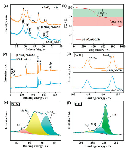
The XRD pattern of the p-SnO2/rGO/Se spheres in reference to f-SnO2/rGO is shown in Fig. 2a. In addition to the typical (110), (101), (200), (211), (310) and (301) diffraction peaks of SnO2, the presence of diffraction peaks attributed to Se confirms the reduction of SeO2 to elemental Se post completion of spray pyrolysis [17-19]. The content of the SnO2, rGO and Se in the p-SnO2/rGO/Se spheres were determined using TG analysis under the air atmosphere (Fig. 2b). The weight loss of the p-SnO2/rGO/Se spheres mainly occurs in the two-stage process. The initial weight loss of 21.8% from 300 ℃ to 540 ℃ could be ascribed to the removal of rGO, while the weight loss at 670-800 ℃ corresponds to the sublimation of elemental Se. Thus, the mass ratio of SnO2 in the p-SnO2/rGO/Se sphere was approximately determined to be 50.0%.

|
Download:
|
| Fig. 2. (a) XRD pattern of p-SnO2/rGO/Se in reference to f-SnO2/rGO spheres. (b) TG curve of the p-SnO2/rGO/Se indicating a two-stage weight loss process. (c) XPS survey spectrum of the p-SnO2/rGO/Se and f-SnO2/rGO spheres with high-resolution spectra profile of (d) Sn 3d, (e) Se 3d and (f) C 1s acquired for p-SnO2/rGO/Se spheres. | |
The chemical state of the p-SnO2/rGO/Se and f-SnO2/rGO spheres was studied using XPS analysis. Unlike the f-SnO2/rGO spheres, the XPS survey spectrum of the p-SnO2/rGO/Se spheres shows the presence of additional Se 3d, Se 3p and Se LMM Auger bands at 59.4, 165.4 and 184.4 eV, respectively, besides typical C and Sn bands (Fig. 2c) [20]. The high-resolution Sn 3d spectra profile for p-SnO2/rGO/Se sphere and f-SnO2/rGO sphere (Fig. 2d) consists of two bands centered at 495.1 and 486.7 eV, which could be attributed to the Sn 3d3/2 and Sn 3d5/2 orbitals. As no change in peak position was noted, it is safe to assume that no structural alteration occurred in the Sn atoms present in SnO2 [17, 21]. Fig. 2e shows the high-resolution XPS spectra profile of Se 3d for the p-SnO2/rGO/Se sphere, with typical bands at 54.7, 55.6 and 56.4 eV attributed to Se 3d5/2, Se 3d3/2 and Se—C bonds, respectively [22, 23]. The C 1s XPS spectra (Fig. 2f) could be divided into three components centered at 284.6, 285.9 and 288.7 eV for C—C, C—O and C—Se bonds, respectively [24, 25].
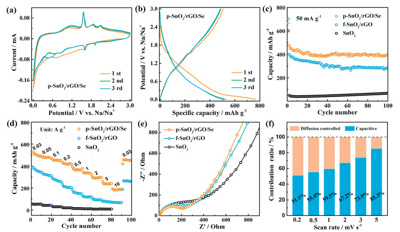
The electrochemical behavior and sodium storage performance of the p-SnO2/rGO/Se spheres were measured by integrating the material in a coin-type half cell configuration with NaClO4/EC + DEC + FEC as an electrolyte. For comparison, the f-SnO2/rGO spheres and SnO2 were devised as competitive anodes for SIBs. Fig. 3a shows the initial three CV scans of p-SnO2/rGO/Se spheres recorded at 0.2 mV/s. A broad peak in the range of 0.6–1.6 V is evident in the initial cathodic scan, which could be ascribed to the formation of solid electrolyte interface (SEI) and the conversion reaction of SnO2 to metallic Sn (Eq. S1 in Supporting information). Furthermore, the peaks located in the range of 0.01-0.6 V could be assigned to the reversible alloying process of Sn ↔ NaxSn (Eq. S2 in Supporting information). Correspondingly, the peaks at 0.46 and 1.13 V in the anodic scan are associated with the dealloying reaction of NaxSn to Sn [26-28]. In comparison to the f-SnO2/rGO and SnO2 electrode (Fig. S3 in Supporting information), several distinct peaks were observed for the p-SnO2/rGO/Se spheres based electrode, including major peaks at 1.6 and 1.9 V (cathodic scan) and 1.56, 1.87 and 2.1 V (anodic scan). These peaks are related to the conversion reactions of Se ↔ Na2Sex [29, 30]. Fig. 3b and Fig. S4 (Supporting information) show the galvanostatic charge/discharge curves for the p-SnO2/rGO/Se referenced against f-SnO2/rGO spheres and SnO2 at a current density of 30 mA/g. In the case of p-SnO2/rGO/Se, the presence of Se provides extra capacity storage sites during the sodiation/de-sodiation process. This enabled the p-SnO2/rGO/Se spheres to exhibit initial charge and discharge capacities of 506.7 and 766.8 mAh/g, respectively, with an initial coulombic efficiency of 66.1%, much higher than the f-SnO2/rGO spheres (59.8%) and SnO2 (11.4%) based electrodes. Fig. 3c shows the cycle performance of p-SnO2/rGO/Se spheres in comparison to its compositional counterparts. As seen, the p-SnO2/rGO/Se spheres retain a high discharge capacity of 397 mAh/g after 100 cycles at a current density of 50 mA/g. In comparison, the f-SnO2/rGO spheres and SnO2 retained only 278.2 mAh/g and 67.9 mAh/g, respectively. This confirmed the superior structural stability of p-SnO2/rGO/Se with the capability to accommodate sizeable volume changes of SnO2 during continuous cycling. The p-SnO2/rGO/Se spheres, based on their pomegranate-like structures, are expected to promote rapid electron transfer, and therefore an improved rate performance of the devised electrode could be anticipated. Fig. 3d shows the rate capability of the p-SnO2/rGO/Se spheres in reference to the f-SnO2/rGO spheres and SnO2. The p-SnO2/rGO/Se spheres exhibit high specific capacities of 506.7, 478.5, 455.1, 421.7, 363.1, 335.5, 291.1 and 237.6 mAh/g at current densities of 0.03, 0.05, 0.1, 0.2, 0.5, 1, 2 and 5 A/g, respectively. The structural configuration enables the p-SnO2/rGO/Se spheres to maintain a capacity of 186.1 mAh/g even at a high current density of 10 A/g, which is almost 3 times that of the f-SnO2/rGO spheres. In addition, when the current density is relaxed back to 0.03 A/g, the p-SnO2/rGO/Se spheres retained a capacity of 458.2 mAh/g, indicating its excellent reversibility and structural stability compared to f-SnO2/rGO spheres.

|
Download:
|
| Fig. 3. Sodium-ion storage behavior and performance of the p-SnO2/rGO/Se spheres. (a) Representative CV curves measured in the potential window of 0.01 V and 3 V with a scan rate of 0.2 mV/s. (b) Corresponding charge/discharge profiles measured at 30 mA/g. (c-e) Cycle performance at a current density of 50 mA/g, rate capability measured at various current densities, and EIS plots for p-SnO2/rGO/Se spheres in reference to SnO2/rGO and SnO2. (f) Bar-graph depicting the distribution of capacitive and diffusion controlled current contribution of for p-SnO2/rGO/Se, when the scan rate changes from 0.2 mV/s to 5 mV/s. | |
The EIS spectra (Fig. 3e) confirms the lower charge-transfer resistance (Rct) for p-SnO2/rGO/Se spheres (206 Ω) in comparison to the f-SnO2/rGO (248 Ω) and SnO2 (388 Ω). Fig. S5 (Supporting information) further shows the EIS spectra of the p-SnO2/rGO/Se sphere after continuous charge-discharge cycles. The decline of Rct, observed after the initial 30 cycles, reflects the improved sodium diffusion efficiency due to the electrochemical activation process of the p-SnO2/rGO/Se sphere electrode. To further understand the electrochemical kinetics of the p-SnO2/rGO/Se spheres, CV scans were recorded at various scan rates from 0.2 mV/s to 5 mV/s (Fig. S6a in Supporting information). The kinetic charge storage mechanism of the electrode could be deduced from the relationship between current (i) and scan rate (v) according to the following equation: i=avb, where b could have a value range from 0.5 to 1. The b value of 0.5 means a diffusion-controlled process, while b = 1 signifies a non-diffusion dominant process with no diffusion limitations. The b value of the p-SnO2/rGO/Se spheres was estimated to be 0.9069, indicating fast reaction kinetics driven by a non-diffusion behavior (Fig. S6b in Supporting information). Futhermore, the contribution of the diffusion-controlled and non-diffusion dominant process in the total capacity could be divided using the equation: i(V)=k1v+k2v1/2, where the k1v and k2v1/2 represent for the non-diffusion dominant and diffusion-controlled currents, respectively. Fig. 3f shows the contribution of capacitive and diffusion controlled current with a gradual increase of scan rates from 0.2 mV/s to 5 mV/s [31-33]. As seen, the non-diffusion controlled current occupies a portion of 51.1% at a low scan rate of 0.2 mV/s, signifying that the diffusion controlled and non-diffusion dominated current give equivalent contribution to the total capacity of the p-SnO2/rGO/Se sphere. The contribution of non-diffusion dominated current increased to 85.3% as the scan rate reached 5 mV/s, which could be attributed to the better dynamics of non-diffusion behavior, resulting in superior rate capability of p-SnO2/rGO/Se spheres.
In summary, p-SnO2/rGO/Se spheres with unique pomegranate-like structures were synthesized using one-pot spray pyrolysis of the SnCl2/GO/SeO2 mixture. The pomegranate-like architectures formed due to the intertwined rGO nanosheets could effectively enhance the rapid electron transfer as well as alleviate the large volume changes of SnO2 during the repeated cycles. When devised as an anode material for SIBs, the p-SnO2/rGO/Se spheres deliver a high capacity of 506.7 mAh/g at 30 mA/g, with a maintained capacity of 188.9 mAh/g at an ultrahigh current density of 10 A/g. The provided experimental results demonstrate the practical working ability of p-SnO2/rGO/Se spheres for advanced SIBs.
Declaration of competing interestThe authors report no declarations of interest.
AcknowledgmentThis work was financially supported by the Beijing Municipal Science and Technology Commission (No. Z181100004718007).
Appendix A. Supplementary dataSupplementarymaterial related to this article can befound, in the online version, at doi:https://doi.org/10.1016/j.cclet.2020.10.006.
| [1] |
B. Dunn, H. Kamath, J.M. Tarascon, Science 334 (2011) 928-935. DOI:10.1126/science.1212741 |
| [2] |
N. Sun, Z. Guan, Q. Zhu, et al., Nano-Micro Lett. 12 (2020) 89. DOI:10.1007/s40820-020-00426-0 |
| [3] |
P. Zhang, Q. Zhu, Z. Guan, et al., ChemSusChem 13 (2020) 1621-1628. DOI:10.1002/cssc.201901497 |
| [4] |
V. Etacheri, R. Marom, R. Elazari, G. Salitra, D. Aurbach, Energy Environ. Sci. 4 (2011) 3243-3262. DOI:10.1039/c1ee01598b |
| [5] |
N. Sun, Z. Guan, Y. Liu, et al., Adv. Energy Mater. 9 (2019) 1901351. DOI:10.1002/aenm.201901351 |
| [6] |
W. Luo, J. Wan, B. Ozdemir, et al., Nano Lett. 15 (2015) 7671-7677. DOI:10.1021/acs.nanolett.5b03667 |
| [7] |
J. Deng, W.B. Luo, S.L. Chou, H.K. Liu, S.X. Dou, Adv. Energy Mater. 8 (2018) 1701428. DOI:10.1002/aenm.201701428 |
| [8] |
N. Sun, Q. Zhu, B. Anasori, et al., Adv. Funct. Mater. 29 (2019) 1906282. DOI:10.1002/adfm.201906282 |
| [9] |
M. Gu, A. Kushima, Y. Shao, et al., Nano Lett. 13 (2013) 5203-5211. DOI:10.1021/nl402633n |
| [10] |
M.A. Kebede, Curr. Opin. Electrochem. 21 (2020) 182-187. DOI:10.1016/j.coelec.2020.02.003 |
| [11] |
J. Liang, C. Yuan, H. Li, et al., Nano-Micro Lett. 10 (2018) 21. DOI:10.1007/s40820-017-0172-2 |
| [12] |
J.Y. Hwang, S.T. Myung, Y.K. Sun, Chem. Soc. Rev. 46 (2017) 3529-3614. DOI:10.1039/C6CS00776G |
| [13] |
Y. Zheng, T. Zhou, C. Zhang, et al., Angew. Chem. Int. Ed. 55 (2016) 3408-3413. DOI:10.1002/anie.201510978 |
| [14] |
A. Jahel, C.M. Ghimbeu, A. Darwiche, et al., J. Mater. Chem. A 3 (2015) 11960-11969. DOI:10.1039/C5TA01963J |
| [15] |
W. Chen, K. Song, L. Mi, et al., J. Mater. Chem. A 5 (2017) 10027-10038. DOI:10.1039/C7TA01634D |
| [16] |
J. Qin, N. Zhao, C. Shi, et al., J. Mater. Chem. A 5 (2017) 10946-10956. DOI:10.1039/C7TA01936J |
| [17] |
H. Liu, X. Zhang, Y. Zhu, et al., Nano-Micro Lett. 11 (2019) 65. DOI:10.1007/s40820-019-0296-7 |
| [18] |
W. Wei, L.X. Song, L. Guo, Chin. Chem. Lett. 26 (2015) 124-128. DOI:10.1016/j.cclet.2014.09.023 |
| [19] |
S. Li, H. Yang, R. Xu, et al., Mater. Chem. Front. 2 (2018) 1574-1582. DOI:10.1039/C8QM00177D |
| [20] |
C. Zheng, M. Liu, W. Chen, L. Zeng, M. Wei, J. Mater. Chem. A 4 (2016) 13646-13651. DOI:10.1039/C6TA05029H |
| [21] |
Y. Liu, P. Zhang, N. Sun, et al., Adv. Mater. 30 (2018) 1707334. DOI:10.1002/adma.201707334 |
| [22] |
W. Dong, H. Chen, F. Xia, et al., J. Mater. Chem. A 6 (2018) 22790-22797. DOI:10.1039/C8TA07662F |
| [23] |
R. Jin, Y. Cui, Q. Wang, G. Li, J. Colloid Interface Sci. 508 (2017) 435-442. DOI:10.1016/j.jcis.2017.08.034 |
| [24] |
P. Zhang, R.A. Soomro, Z. Guan, N. Sun, B. Xu, Energy Storage Mater. 29 (2020) 163-171. DOI:10.1016/j.ensm.2020.04.016 |
| [25] |
J. Xu, J. Zhu, C. Gong, et al., Chin. Chem. Lett. 31 (2020) 1039-1043. DOI:10.1016/j.cclet.2020.02.050 |
| [26] |
D. Ma, Y. Li, H. Mi, et al., Angew. Chem. Int. Ed. 57 (2018) 8901-8905. DOI:10.1002/anie.201802672 |
| [27] |
M. Wang, X. Wang, Z. Yao, et al., ACS Appl. Mater. Interfaces 11 (2019) 24198-24204. DOI:10.1021/acsami.9b08378 |
| [28] |
L. Fan, X. Li, B. Yan, et al., Adv. Energy Mater. 6 (2016) 1502057. DOI:10.1002/aenm.201502057 |
| [29] |
H. Wang, S. Li, Z. Chen, H.K. Liu, Z. Guo, RSC Adv. 4 (2014) 61673-61678. DOI:10.1039/C4RA10967H |
| [30] |
L. Zeng, W. Zeng, Y. Jiang, et al., Adv. Energy Mater. 5 (2015) 1401377. DOI:10.1002/aenm.201401377 |
| [31] |
X. Xie, K. Kretschmer, B. Anasori, et al., ACS Appl. Nano Mater. 1 (2018) 505-511. DOI:10.1021/acsanm.8b00045 |
| [32] |
Y. Ding, Y. Chen, N. Xu, et al., Nano-Micro Lett. 12 (2020) 54. DOI:10.1007/s40820-020-0381-y |
| [33] |
X. Guo, J. Zhang, J. Song, et al., Energy Storage Mater. 14 (2018) 306-313. DOI:10.1016/j.ensm.2018.05.010 |