 2021, Vol. 32


Metal-free carbon nitride (CN) photocatalyst has attracted wide attention of researchers because of its non-toxic, good visible light response and excellent catalytic effect [1-7]. To further optimize its photocatalytic effect, scientists have done a lot of research work: Some carbon nitride materials started by adjusting the ratio of carbon and nitrogen elements to increase the catalytic efficiency [8-12]. For example, Li et al. synthesized high efficiency CN photocatalyst with different carbon and nitrogen ratios [8]; or by controlling the carbon nitride morphology to increase the specific surface area (active point) of the materials [13-17], such as Huang et al. prepared porous carbon nitride materials with a simple method, which successfully improved the photocatalytic efficiency of CN materials [13]; some of work started from elements doped to adjust the band gap of CN [18-22]. For example, Thaweesak et al. successfully synthesized boron doped CN materials to improve photocatalytic activity [18]. For another example, Sun et al. successfully doped oxygen elements into graphene phase CN, greatly improving the performance of photocatalytic hydrogen production [19]; again, such as Lan et al. successfully doped bromine into CN heterojunctions were constructed to improve the catalytic effect of photocatalysts and even achieve the overall water splitting [23-28]. Such as Liu et al. combined V2O5 with CN into a heterojunction structure, effectively improving the efficiency of photocatalytic hydrogen and oxygen production [23]; besides, the adding chemical groups on the surface of two-dimensional (2D) CN material was also an effective method to improve the photocatalytic efficiency [29-31]. For example, Nguyen et al. introduced hydroxyl groups into g-C3N4, which achieved the improvement of photocatalytic hydrogen production efficiency [30]. In conclusion, these methods have effectively improved the photocatalytic effect of CN photocatalysts.
To date, researchers have found that the doping of non-metallic halogen elements could significantly increase the hydrogen production effect of CN photocatalysts [32-36], for example: Iqbal et al. doped iodide ions in the CN nanosheets, which increased the efficiency of photocatalytic hydrogen production to 6.5 times that of raw materials [32]; again, such as Lan et al. have successfully doped bromine into CN [33]. Those doping methods were very good to maintain metal-free character. At the same time, CN photocatalysts doped with halogen elements could also be better combined with other semiconductor photocatalysts, so as to further improve the photohydrogen production efficiency [37, 38], such as Zhou et al. synthesized a CN material with sponge structure by using ammonium chloride precursor and melamine, and then combined this material with molybdenum disulphide to improve the material's electro-optical response characteristics [37]. So, the basic research on the modification of CN by halogen elements played a role in promoting its application.
In recent years, we have also designed modification of CN photocatalyst. First, in 2018, we discovered for the first time that 2D organic CN of several atomic layers thickness could be prepared by simple water heat treatment [39]. The effect of roasting temperature on the morphology of CN was studied and found that this preparation method could optimize the photocatalytic efficiency of CN. It has an exceptionally good application prospect for its subsequent morphology control, doping and heterogeneous structural design. Then, in 2020, we designed a CN photocatalyst containing P/N junction, which not only greatly improved the photocatalytic hydrogen production efficiency, but also had a good effect of overall water splitting [40]. In the process of accumulating a large number of literatures, experimental operation and data analysis in the early stage, we found that the hydrogen production effect of CN photocatalyst modified by hydrothermal fluorinated method was better than that of pure CN photocatalyst, so we carried out the following theoretical simulation calculation, experimental verification, data analysis and other work.
In this work, the first theoretical principle was used to calculate and analyze the fluorination and hydroxylation of g-C3N4. The band gap of the photocatalyst will widen by doping of a small number of fluorine ions. And the doping of a certain hydroxyl groups can move the valence band up of the photocatalyst (or say generate a shallow energy level in the band gap). The existence of shallow energy level enables it to produce more photoelectrons and holes under the same illumination energy, thus improving the photocatalytic effect of CN photocatalyst. Based on the theoretical analysis, layered CN was fluorinated by hydrothermal method (we did not obtain a large size CN nanosheets, but a smaller size CN sheet, and its photocatalytic effect was better than that of layered CN). Next, we analyzed its structure and photoelectric response, and the reaction mechanism of photocatalytic was also discussed. Therefore, the study of this work provided a reasonable theoretical support for explaining why the hydrothermal fluorinated method can improve photocatalytic activity of CN.
Here, we have successfully synthesized F—CN with the following reagents and experimental methods: Analytical-grade melamine, alcohol, ammonium fluoride, triethanolamine and chloroplatinic acid were purchased from Sinopharm Chemical Reagent Co. Ltd. (Shanghai). All reagents were used as received. Firstly, 5 g melamine as the raw material, which was first heat treated by hydrothermal synthesis at 180 ℃ for 24 h, filtered and dried [39, 40]. And the layered CN was transferred into a tubular furnace under the protection of high purity argon at 550 ℃ for 0 h [39]. Then, the lamellar CN was treated with ammonium fluoride 180 ℃ for 24 h, then filtered and dried, F—CN would be synthesized. And the bulk melamine raw material was directly treated for 2 h in air at 550 ℃ in contrast experiment [39].
Hydrogen evolution reaction measurement: The photocatalytic reactions were carried out in a Pyrex reaction cell connected to a closes gas circulation an evacuation system: 0.05 g catalyst (1% Pt) was dispersed in 100 mL aqueous solution containing 20 mL triethanolamine as sacrificial agent. Then the suspension be thoroughly degassed and irradiated by a Xe lamp (300 W) equipped with an optical cut off filter (λ > 420 nm) to eliminate ultraviolet light. The temperature of the reactant solution was maintained at 279 K by flowing cooling water during the reaction.
The amount of H2 produced was analysed using an online gas chromatography. The activities of different catalysts were compared using the average rate of H2 evolution in the first 7 h. The apparent quantum efficiency (AQE) was also measured in similar conditions by using the following typical equation (Eq. 1) [40]:

|
(1) |
Photoelectrochemical (PEC) activity measurements: PEC test systems contained a CHI760E workstation (Shanghai Chenhua, China) with a three-electrode configuration using the prepared samples as the working electrodes, a Pt plate as the counter electrode, Ag/AgCl as the reference electrode and a 300 W Xe lamp equipped with an optical cut off filter (λ > 420 nm) as the light source. Na2SO4 aqueous solution (0.5 mol/L) was used as the electrolyte. The working electrodes were prepared as follows: 10 mg the as-prepared CN were dispersed in absolute ethanol and the suspension was directly deposited onto an FTO conductive glass plate and then dried at 80 ℃ in a vacuum oven [40].
Scanning electron microscope (SEM) was performed with a Hitachi S-4800 SEM. X-ray diffraction (XRD) patterns of the samples were recorded on a Bruker D8 Advance powder X-ray diffractometer using Cu Kα (λ = 0.15406 nm) radiation. Fourier transform infrared spectroscopy (FTIR) spectrum was carried out with a Thermo-Nicolet Nexus 670 infrared spectrometer. UV–vis diffuse reflectance spectra of the samples were recorded on a Shimadzu UV-2550 spectrophotometer within a wavelength range of 300–800 nm. The photoluminescence spectra of the photocatalysts were detected using an Edinburgh FLS920 spectrometer. X-ray photoelectron measurements were carried out using a monochromatized X-ray photoelectron spectroscopy (XPS) spectrometer (a Thermo Fisher ESCALAB 250) with Al (Kα) radiation as the probe and a 500-mm analysis spot size. The base chamber pressure was 2 × 10⁻⁹ mbar.
The theoretical calculations were performed based on the plane-wave spin-polarized density functional theory (DFT) as implemented in the Vienna Ab-initio Simulation Package (VASP). The exchange-correlation energy functions based on generalized gradient approximation (GGA) with Perdew-Burke-Ernzerhof (PBE) was used. The energy cut-off for the plane-wave basis set was 500 eV, and the k-point is set to be 4 × 4 × 1. The convergence for the energy and the force were set to be 10-5 eV and 0.03 eV/Å, respectively. To obtain the reliable band gap, the band structures were calculated by using the HSE06 functional.
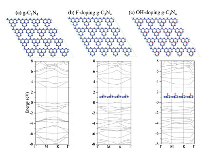
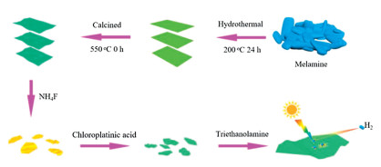
First, g-C3N4 was chosen as the research object of modeling calculation because it was a typical CN material [41-46]. As shown in Fig. 1, the first theoretical principle was used to calculate and analyze g-C3N4, fluorination and hydroxylation of g-C3N4. Fig. S1a (Supporting information) showed a typical g-C3N4 structure with valence band around 0 eV and conduction band around 2.97 eV, that is, the band gap was about 2.97 eV. With F atoms doping, the band gap of g-C3N4 was enhanced from 2.97 eV to 3.37 eV, conduction band moved up and the valence band maximum was increased from 0 to 0.09 eV in Fig. S1b (Supporting information). And doped OH into g-C3N4 in Fig. 1c, its valence band has moved up very significantly from 0 to 0.126 eV, conduction band also moved up and the band gap reached about 3.33 eV. Based on the above calculation, it can be concluded that fluorination and hydroxylation of CN can make the valence band and conduction band move up and widen the band gap of photocatalyst. All these changes are beneficial to hydrogen production effect of CN photocatalyst. Based on this, we carried out a series of experiments and analysis: As shown in Fig. 2, layered CN organic precursors could be prepared by heat treating ordinary melamine raw materials with hydrothermal method. Then, under the protection of nitrogen, it was quenched at 550 ℃ to obtain a layered CN. The lamellar CN was then treated with ammonium fluoride 180 ℃ for 24 h to obtain the small lamellar CN nanosheets. With the help of co-catalyst (chloroplatinic acid) and sacrificial agent (triethanolamine), a large amount of hydrogen was produced by water-splitting under simulated visible light [47-51].

|
Download:
|
| Fig. 1. (a-c) Molecular structure modeling diagrams (above) and electronic band structures diagrams (below). | |

|
Download:
|
| Fig. 2. Experimental process diagram of CN photocatalyst. | |
Fig. S1 (Supporting information) was the SEM of the prepared layered CN nanosheets. The layered structure of CN was clearly shown in Figs. S1a and b, and the local self-curling phenomenon was due to electrostatic effect of the layered CN. Due to the incorporation of fluorine atoms or hydroxyl groups, the layered CN was cut and corroded into many interconnected CN nanosheets (labeled F—CN) in Figs. S1c and d [52-54]. In this way, the cut and corroded CN edges and faces would be doped in F atoms and OH groups, while the material itself was still CN.
The XRD and infrared spectroscopy (IR) characterization of the photocatalyst before and after fluorination and hydroxylation were shown in Fig. S2 (Supporting information). The crystal structure of the layered and F—CN nanosheets were recorded by XRD in Fig. S2a. The crystallization property of the CN was very good, especially after the fluoridation of CN (JCPDS No. 50-0664) [55, 56]. The width of the half peak of F—CN became narrower and the peak became sharper at 27.6°, which was also a typical phenomenon (002) peak of nanosheets. But the weak interplanar structural packing peak (001) of CN slight shifted after fluorination and hydroxylation. This was due to changes in the CN interlayer forces caused by the insertion of fluorine atoms and OH groups [57]. At the same time, the chemical structure of CNs was characterized by infrared test in Fig. S2b, and C—F bond existed near 1198 cm-1. It is proved that fluorine atoms enter the molecular structure of CN. The doped of fluorine also caused a change in the absorption peak ~1400–1600 cm-1 (sp2 C=N and sp3 C—N bonds) [58]. The absorption peak of 3200 cm-1 was belong to N—H band stretching vibration in layered CN, but multiple stretching vibration peaks of O—H appeared in F—CN (~3050–3600 cm-1) due to hydrothermal reactions [59]. This suggested that the hydrothermal process also hydroxylated CN while fluorinating them.
The chemical states and surface elements of photocatalysts were characterized by XPS in Fig. S3 (Supporting information). The XPS spectrum showed that carbon and nitrogen were the main elements in both CN materials. Compared with Figs. S3a and b, F 1s peak of F—CN was obvious in Fig. S3b, and the intensity of N 1s peak and C 1s peak did not change significantly. It was worth noting that the intensity of oxygen peak was significantly enhanced after hydrothermal treatment, this was because the oxygen-free roasted CN contains many broken bonds of carbon, and during the hydrothermal reaction with water, the CN was hydroxylated. So, there's a C—O peak at 288.5 eV in Fig. S3f [60, 61]. Comparison between Figs. S3e and h, at 678–692 eV, there were an obvious F 1s peak appeared in this interval after fluorination, indicating that the layered CN were also successfully fluorinated.
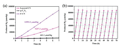
Hydrogen production tests of CN photocatalysts under visible light were shown in Fig. 3a, in the same experiment, the average efficiency of photocatalytic hydrogen production of F—CN reached a staggering 12, 593.2 μmol/hg. This is significantly higher than those of layered CN (5257.3 μmol/hg) and g-C3N4 (441.1 μmol/hg). In order to evaluate the durability of F—CN in this work, we conducted a 70-h cycle hydrogen production tests for the photocatalyst in Fig. 3b. The photocatalytic activity of the photocatalytic material showed no obvious decline during 70-h cycle.

|
Download:
|
| Fig. 3. (a) Hydrogen production of g-C3N4, F—CN and layered CN; (b) Hydrogen evolution cycle curve of F—CN photocatalyst. | |
By comparing the typical nitrogen adsorption-desorption isotherms of the CN photocatalysts before and after fluorination and hydroxylation (Figs. S4a and b in Supporting information), we found that the specific surface area of the F—CN material was as high as 54.1 m2/g, which was twice higher than the previous specific surface area (layered CN) of 27.1 m2/g. With the specific surface area increasing, the number of active sites of F—CN materials also increased significantly compared with that of layered CN [62, 63]. UV-diffuse reflectance spectra of different CN photocatalysts were showed in Fig. S4c (Supporting information). By comparing the two absorption spectra, the band edge of the F—CN photocatalyst was about 450 nm, which was approximate for the value (before reaction). However, because of the fluorination and hydroxylation, F—CN photocatalyst had a blue shift in the absorption spectrum [47]. The AQE of the F—CN photocatalytic materials at 420 nm and 475 nm reached 10.9% and 2.9%, respectively. Corresponding the values of layered CN photocatalysts before reaction were 7.1% (420 nm) and 1.8% (475 nm) in Fig. S4d (Supporting information). This indicated that AQE of the CN materials was greatly improved after fluorination and hydroxylation.
The photoelectron-hole pairs separation of CN photocatalysts were measured by measuring the photocurrent response curve, and the transient photocurrent response of different CN photocatalysts were recorded during the on-off cycles of illumination in Fig. S5a (Supporting information). When the device simulating solar illumination was turned on, as shown in the chart, the photocurrent increased sharply. When the device was turned off, the photocurrent quickly returned to the dark current state. The photocurrent was stable and repeatable in these on-off irradiation cycles. As shown in Fig. S5a, F—CN photocatalyst showed excellent photocurrent response characteristics. By testing the photoluminescence spectra of F—CN, layered CN and g-C3N4 photocatalysts in Fig. S5b (Supporting information), we found that the recombination of electron and hole of F—CN was delayed due to its interface interaction (Super-small F—CN nanosheets). Meanwhile, by measuring the ns-level time-resolved photoluminescence (PL) spectra of layered CN and F—CN monitored at 450 nm under 420 nm excitation, it could be seen that the effective life of photoelectron (F—CN) reached 14.13 ns, nearly double the effective life of layered CN (7.41 ns). So, both test results showed that the photocarrier life of photocatalyst was enhanced after fluoridation and hydroxylation of CN.
The band gap of CN photocatalysts were calculated by the Plot of (AEphoton)2~Ephoton (Fig. S6a in Supporting information) from the UV–vis diffuse reflectance spectra. By calculating the slope of the image curve, the band gap width of layered CN materials was 2.842 eV, while the band gap width of F—CN materials was about 2.828 eV (the band gap between the two catalysts was close). The broad-band gap of catalysts might have higher carrier mobility, which had positive significance for the improvement of photocatalytic efficiency. The valence band maximum energies of the two materials were shown in Fig. S6b (Supporting information), F—CN and layered CN all had a valence band of 1.47 eV, but F—CN also had a special valence band at 0.73 eV [56-59]. This was because the solid-layered CN through the hydrothermal fluorination process, the fluorination reaction was not complete. A portion of layered CN was fluorinated, and a large portion was not fluorinated, but hydroxylated. This conjecture was consistent with the previous IR test results. The addition of OH groups can move the valence band of CN up (or generate a shallow energy level in the band gap of the photocatalyst) in Fig. S1c.
In terms of the transfer of photoinduced carriers, the EIS curves (Fig. S7 in Supporting information) reveal that F—CN possesses lower carrier transfer resistance than layered CN, as indicated by the smallest semicircle diameter [64, 65]. Besides, Mott–Schottky analysis was performed to confirm the type of F—CN, from Fig. S8 (Supporting information), it was clearly showing a positive slope for the n-type in the linear region of the plot [66, 67]. Therefore, this preparation method gives rise to the unique CN heterostructure.
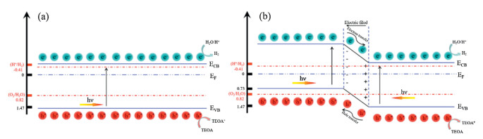
The band structure of layered CN photocatalyst was a common semiconductor structure (Fig. 4a), and the band gap had a span the reduction potential of hydrogen production and the oxidation potential of oxygen production. In the presence of sacrificial agents, this band structure reflected the process of photocatalytic hydrogen production under visible light irradiation in Fig. 4a. But F—CN photocatalyst had a shallow energy level (0.73 eV) in the band gap (Fig. 4b). This unique CN heterostructure ensures that the photocatalyst can generate more photogenerated electrons and holes under same light, which greatly improves the activity and efficiency of CN photocatalyst.

|
Download:
|
| Fig. 4. Photocatalytic schematic diagrams of layered CN (a) and (b) F—CN photocatalysts. | |
In this work, in order to explain why the hydrothermal fluorinated method can improve photocatalytic activity of CN. This work has a great guiding effect on the development of CN photocatalyst. Firstly, based on first theoretical principle, the influence of the band gap was revealed of fluorination and hydroxylation of CN photocatalyst: With F atoms and OH doping, the band gap of CN was significantly improved, conduction band and valence band moved up. Secondly, F—CN photocatalyst with F atoms and OH was successfully synthesized by a clever design. And then, the reasons why F—CN photocatalyst was more effective than that of traditional CN photocatalyst were fully discussed: From the photocatalytic effect of photocatalyst to the morphology, structure, composition, specific surface area, visible light absorption response, photo-induced carrier life and so on. And obtained the conclusion: Synthesized of F—CN photocatalyst had unique heterostructure, high specific surface area, superior visible light absorption response and photo-induced carrier life by hydrothermal fluorinated method.
Declaration of competing interestThe authors report no declarations of interest.
AcknowledgmentsThis work was supported by the National Natural Science Foundation of China (Nos. 51802177, 51672109), Independent Cultivation Program of Innovation Team of Ji'nan City (No. 2019GXRC011), the Major Basic Program of the Natural Science Foundation of Shandong Province (Contract ZR2018ZC0842), and Natural Science Foundation of Shandong Province (No. ZR2018BEM019). All the authors contributed to preparation, characterization and analysis structure and performance of materials. All the authors discussed the results and commented on the manuscript.
Appendix A. Supplementary dataSupplementarymaterial related to this article can befound, in the online version, at doi:https://doi.org/10.1016/j.cclet.2020.11.033.
| [1] |
D. Ren, Z. Liang, Y.H. Ng, et al., Chem. Eng. J. 390 (2020) 124496. DOI:10.1016/j.cej.2020.124496 |
| [2] |
X. Li, J.G. Yu, M. Jaroniec, X.B. Chen, Chem. Rev. 119 (2019) 3962-4179. DOI:10.1021/acs.chemrev.8b00400 |
| [3] |
G. Zhang, G. Li, T. Heil, et al., Angew. Chem. Int. Ed. 58 (2019) 3433-3437. DOI:10.1002/anie.201811938 |
| [4] |
R.C. Shen, J. Xie, Q.J. Xiang, et al., Chin. J. Catal. 40 (2019) 240-288. DOI:10.1016/S1872-2067(19)63294-8 |
| [5] |
Z. Wang, Y. Inoue, T. Hisatomi, et al., Nat. Catal. 1 (2018) 756-763. DOI:10.1038/s41929-018-0134-1 |
| [6] |
Y.J. Ren, D.Q. Zeng, W.J. Ong, Chin. J. Catal. 40 (2019) 289-319. DOI:10.1016/S1872-2067(19)63293-6 |
| [7] |
Y.B. Li, Z.L. Jin, L.J. Zhang, K. Fan, Chin. J. Catal. 40 (2019) 390-402. DOI:10.1016/S1872-2067(18)63173-0 |
| [8] |
W. Li, Z. Guo, L. Jiang, et al., Chem. Sci. 11 (2020) 2716-2728. DOI:10.1039/C9SC05060D |
| [9] |
N.N. Meng, W. Zhou, Y.F. Yu, Y. Liu, B. Zhang, ACS Catal. 9 (2019) 10983-10989. DOI:10.1021/acscatal.9b03895 |
| [10] |
G.Y. Zhuge, W.D. Zhang, Chem. Cat. Chem. 11 (2018) 1045-1056. |
| [11] |
M.Y. Yin, X. Chen, Y.Q. Wan, et al., Chem. Cat. Chem. 6 (2020) 1512-1518. |
| [12] |
B. Zhang, T.J. Zhao, H.H. Wang, ACS Appl. Mater. Interfaces 38 (2019) 34922-34929. |
| [13] |
H.W. Huang, K. Xiao, N. Tian, et al., J. Mater. Chem. A 5 (2017) 17452-17463. DOI:10.1039/C7TA04639A |
| [14] |
F. Guo, L.J. Wang, H.R. Sun, M.Y. Li, W.L. Shi, Inorg. Chem. Front. 7 (2020) 1770-1779. DOI:10.1039/D0QI00117A |
| [15] |
J. Barrio, M. Shalom, ACS Appl. Mater. Interfaces 46 (2018) 39688-39694. |
| [16] |
Y.N. Xin, Y. Huang, K. Lin, Y.F. Yu, B. Zhang, Sci. Bull. 63 (2018) 601-608. DOI:10.1016/j.scib.2018.03.015 |
| [17] |
N.N. Vu, S. Kaliaguine, T.O. Do, ACS Sustain. Chem. Eng. 2 (2020) 853-863. |
| [18] |
S. Thaweesak, S. Wang, M. Lyu, et al., Dalton Trans. 46 (2017) 10714-10720. DOI:10.1039/C7DT00933J |
| [19] |
S.D. Sun, J. Li, J. Cui, et al., Inorg. Chem. Front. 5 (2018) 1721-1727. DOI:10.1039/C8QI00242H |
| [20] |
F. Wei, Y. Liu, H. Zhao, et al., Nanoscale 9 (2018) 4515-4522. |
| [21] |
L. Zhang, Z. Jin, H. Lu, et al., ACS Omega 11 (2018) 15009-15017. |
| [22] |
P. Kumar, K. Piyush, P. Ajay, et al., Adv. Opti. Mater. 19 (2020) 1901275. |
| [23] |
B.Q. Liu, D.G. Yin, F.F. Zhao, et al., J. Phys. Chem. C 123 (2019) 4193-4203. |
| [24] |
Q.G. Hao, Y.H. Song, Z. Mo, et al., RRL Solar 5 (2020) 1900538. |
| [25] |
W.L. Shi, J.B. Wang, S. Yang, et al., J. Chem. Tech. Biotech. 95 (2020) 2129-2138. DOI:10.1002/jctb.6398 |
| [26] |
J. Ran, W. Guo, H. Wang, et al., Adv. Mater. 25 (2018) 1800128. |
| [27] |
Y. Zheng, Y.L. Chen, B.F. Gao, B.Z. Lin, X.C. Wang, Adv. Funct. Mater. 4 (2020) 2002021. |
| [28] |
Q. Wang, S.C. Yu, W. Qin, X.H. Wu, Nanoscale Adv. 2 (2020) 274-285. DOI:10.1039/C9NA00634F |
| [29] |
C. Ye, J.X. Li, H.L. Wu, et al., ACS Appl. Mater. Interfaces 10 (2018) 3515-3521. DOI:10.1021/acsami.7b14896 |
| [30] |
C.C. Nguyen, T.O. Do, ACS Appl. Energy Mater. 9 (2018) 4716-4723. |
| [31] |
H. Gao, Y. Guo, Z. Yu, et al., Chem. Sus. Chem. 18 (2019) 4285-4292. |
| [32] |
W. Iqbal, B. Yang, X. Zhao, et al., Catal. Sci. Technol. 10 (2020) 549-559. DOI:10.1039/C9CY02111F |
| [33] |
Z.A. Lan, G.G. Zhang, X.C. Wang, Appl. Catal. B: Environ. 192 (2016) 116-125. DOI:10.1016/j.apcatb.2016.03.062 |
| [34] |
Y.Q. Huang, Q. Yan, H.J. Yan, et al., Chem. Cat. Chem. 9 (2017) 4083-4089. |
| [35] |
Q.H. Zhu, Z. Chen, L.N. Tang, et al., Int. J. Hydrog. Energy 22 (2019) 27704-27712. |
| [36] |
Y.Q. Huang, Q. Yan, H.J. Yan, et al., Chem. Cat. Chem. 9 (2017) 4083-4089. |
| [37] |
B. Zhou, B. Yang, M. Waqas, et al., RSC Adv. 10 (2020) 19169-19177. DOI:10.1039/D0RA03759A |
| [38] |
R. Tang, S.J. Zhou, H. Li, et al., Appl. Catal. B: Environ. 265 (2020) 118583. DOI:10.1016/j.apcatb.2019.118583 |
| [39] |
G. Zhao, Y. Cheng, Y. Wu, X. Xu, X. Hao, Small 14 (2018) 1704138. DOI:10.1002/smll.201704138 |
| [40] |
G. Zhao, S.H. Hao, J.H. Guo, et al., Chin. J. Catal. 42 (2021) 501-509. DOI:10.1016/S1872-2067(20)63670-1 |
| [41] |
Y. Li, T. Kong, S. Shen, Small 15 (2019) 1900772. DOI:10.1002/smll.201900772 |
| [42] |
Y.P. Pang, M.N. Uddin, W. Chen, et al., Adv. Mater. 31 (2019) 1905540. DOI:10.1002/adma.201905540 |
| [43] |
G. Zhang, L. Lin, G. Li, et al., Angew. Chem. Int. Ed. 57 (2018) 9372-9376. DOI:10.1002/anie.201804702 |
| [44] |
G.H. Jia, Y.P. Pang, J.J. Ning, U. Banin, B.T. Ji, Adv. Mater. 31 (2019) 1900781. DOI:10.1002/adma.201900781 |
| [45] |
D.C. Chen, H.Y. Zhang, Y.G. Li, et al., Adv. Mater. 30 (2018) 1803351. DOI:10.1002/adma.201803351 |
| [46] |
Y. Kang, Y. Yang, L. Yin, et al., Adv. Mater. 28 (2016) 6471-6477. DOI:10.1002/adma.201601567 |
| [47] |
X. Li, W. Bi, L. Zhang, et al., Adv. Mater. 28 (2016) 2427-2431. DOI:10.1002/adma.201505281 |
| [48] |
H. Xu, J. Hu, D. Wang, et al., J. Am. Chem. Soc. 137 (2015) 13440-13443. DOI:10.1021/jacs.5b08773 |
| [49] |
M. Ismael, J. Alloys Compd. 846 (2020) 156446. DOI:10.1016/j.jallcom.2020.156446 |
| [50] |
N. Xiao, S.S. Li, S. Liu, et al., Chin. J. Catal. 40 (2019) 352-361. DOI:10.1016/S1872-2067(18)63180-8 |
| [51] |
J.Q. Wen, J. Xie, X.B. Chen, X. Li, Appl. Surf. Sci. 391 (2017) 72-123. DOI:10.1016/j.apsusc.2016.07.030 |
| [52] |
X.B. Huang, Z.Y. Wu, H.Y. Zheng, W.J. Dong, G. Wang, Green Chem. 20 (2018) 664-670. DOI:10.1039/C7GC02231J |
| [53] |
Z. Li, Y.N. Ma, X.Y. Hu, E.Z. Liu, J. Fan, Chin. J. Catal. 40 (2019) 434-445. DOI:10.1016/S1872-2067(18)63189-4 |
| [54] |
G. Zhao, T. Wang, Y. Shao, et al., Small 13 (2017) 1602243. DOI:10.1002/smll.201602243 |
| [55] |
Q. Liu, X. Wang, Q. Yang, Z. Zhang, X. Fang, Appl. Catal. B: Environ. 225 (2018) 22-29. DOI:10.1016/j.apcatb.2017.11.044 |
| [56] |
J. Zhang, S. Gong, N. Mahmood, et al., Appl. Catal. B: Environ. 221 (2018) 9-16. DOI:10.1016/j.apcatb.2017.09.003 |
| [57] |
M.Z. Rahman, C.B. Mullins, Acc. Chem. Res. 52 (2019) 248-257. DOI:10.1021/acs.accounts.8b00542 |
| [58] |
M.Z. Rahman, Y. Tang, P. Kwong, Appl. Phys. Lett. 112 (2018) 253902. DOI:10.1063/1.5038785 |
| [59] |
M.Z. Rahman, K. Davey, Phys. Rev. Mater. 2 (2018) 125402. DOI:10.1103/PhysRevMaterials.2.125402 |
| [60] |
Y.B. Li, Z.L. Jin, L.J. Zhang, K. Fan, Chin. J. Catal. 40 (2019) 390-402. DOI:10.1016/S1872-2067(18)63173-0 |
| [61] |
S. Javaid, X.J. Li, F. Wang, et al., J. Mater. Chem. C 7 (2019) 14517. DOI:10.1039/C9TC03538A |
| [62] |
G. Zhao, Y.L. Cheng, P.X. Sun, et al., Electrochim. Acta 331 (2020) 135262. DOI:10.1016/j.electacta.2019.135262 |
| [63] |
W. Chen, X.J. Li, F. Wang, et al., Small 16 (2020) 1902231. DOI:10.1002/smll.201902231 |
| [64] |
M. Shao, Y. Shao, S. Ding, et al., ACS Sustain. Chem. Eng. 7 (2019) 4220-4229. DOI:10.1021/acssuschemeng.8b05917 |
| [65] |
X. Zhou, Y. Fang, X. Cai, et al., ACS Appl. Mater. Interfaces 12 (2020) 20579-20588. DOI:10.1021/acsami.0c04241 |
| [66] |
L. Paramanik, K.H. Reddy, S. Sultana, K. Parida, Inorg. Chem. 57 (2018) 15133-15148. DOI:10.1021/acs.inorgchem.8b02364 |
| [67] |
D. Priyadarshani, P. Leuaa, R. Maurya, A. Kottantharayil, M. Neergat, J. Phys. Chem. C 124 (2020) 19990-19999. DOI:10.1021/acs.jpcc.0c05616 |