 2021, Vol. 32


b School of Materials Science and Engineering, Zhengzhou University, Zhengzhou 450001, China;
c Institute of Chemistry, Chinese Academy of Sciences, Beijing 100190, China
As world's fossil fuels are estimated to be depleted, developing a clean and sustainable energy source has become a major scientific challenge facing humanity in the 21st century [1]. The past several decades have seen increasing attention paid to solar energy since the photon source is inexhaustible [2, 3]. Among the various devices using solar energy, organic solar cells (OSCs) with a bulk-heterojunction (BHJ) photoactive layer comprising a p-type electron donor and a n-type electron acceptor show promise among the emerging energy technology, owing to the unique advantages such as low cost, light weight, large-area manufacturing and ease of fabricating flexible and translucent devices, etc. [4, 5]. Currently in this filed, the power conversion efficiency (PCE) as a key parameter has up to 16% with the advent of A-DA′D-A non-fullerene acceptors (NFAs) [6, 7]. However, tremendous efforts are still made into the innovation of material science and device engineering for commercial applications.
In terms of photoactive materials, the recently reported star molecule Y6 by Zou et al. has opened the door to high-efficient OSCs [11]. At present, fine-tuning the molecular structure of Y6 and exploring the related mechanism of molecular structure-performance are important for the further development of OSCs [8]. Several available design strategies include (ⅰ) variation of the electron-deficient core [9], (ⅱ) extension of the conjugate skeleton [10, 11], (ⅲ) terminal change [12-14] and (ⅳ) side chain engineering [15]. Among these, the side chain can effectively regulate the intrinsic properties of materials such as solubility, crystallinity and intermolecular packing, etc., which dramatically affects morphology of active layer and then device performance [16, 17]. Recently, Yan and Zou et al. explored the branching points of the central alkyl chains on the pyrroles of Y6 [18]. They found that the 3rd-position branching N3 exhibits the increased solubility, the more excellent morphological properties, and therefore the improved PCE of the PM6-based devices compared to the 2nd-position branching Y6. This result suggests that introduction of branched alkyl chains at the 3rd-position into pyrroles is a good modification to improve the photovoltaic properties. In the meantime, it remains to be seen whether this side chain change is still applicable to other derivatives. Among the design strategy of NFAs, fluorination is known to be an important factor for high photovoltaic properties [19-21]. However, NFAs with chlorinated IC terminal rarely precede the fluorinated counterparts [22-24]. For example, IT-4F improves PCE of the PM6-based device to 13.59% while IT-4Cl only achieves the efficiency of 12.67% [24]. Particularly in the A-DA′D-A type acceptors, Y18 employing PM6 as an electron donor achieves a high PCE of 16.52% while Y19, the chlorinated counterpart, obtains an optimal PCE of only 12.76%, due to the decrease in FF from 0.76 to 0.68. A major reason is that, compared to fluorination, chlorination further enhances the self-aggregation trend and reduces the solubility [25-27]. Therefore, it is more feasible that an appropriate modification of alkyl chain is taken to optimize the structure for chlorinated NFAs. Recently, Hou et al. used the longer side chains of 2-butyloctyl instead of the 2-ethylhexyl and synthesized BTP-4Cl-12 [15]. With superior processability and desirable morphology, BTP-4Cl-12 allows more than 17% PCE in the PM6-based devices, which is one of the highest efficiencies among binary OSCs. With this in mind, it is meaningful to apply the 3rd-position branching strategy to modify alkyl chain of the chlorinated derivatives.
Besides the above modification of molecular structure, the selection of the processing solvent is another approach to ensure sufficient solubility of the photoactive materials rather than sacrificing their crystallinity [28, 29]. Currently, the binary solvent strategy of adding a little of additive such as 1, 8-diiodooctane (DIO) or 1-chloronaphthalene (CN) to main solvent such as chloroform (CF) or chlorobenzene (CB) has been widely used in casting device [10, 15, 30-33]. Except for this, other types of solvent strategies such as ternary solvent, this combination of two main solvents and one additive or one main solvent and two additives, have also been developed to balance solubility and crystallinity [34-37]. Although screening a suitable solvent is a tedious process, the benefits with regard to OSCs remain to be reliable. Each ingredient in the processing solvent shows a different dissolving capacity for the blend materials and the variant boiling points as well as evaporation rates during spin-coating, which leads to diversity in their interactions between donor and acceptor [35, 38]. Therefore, changes in the solvents and their volume ratio can manipulate organization of the blend film. In order to maximize the photovoltaic performance of OSCs, proper solvent selection is essential.
Herein, the 3rd-position branching strategy is adopted to construct a new NFA, denoted as Y19-N3, by using 3-ethylheptyls instead of 2-ethylhexyls on pyrroles of Y19. Similar to Y19, Y19-N3 exhibits the LUMO level of -4.02 eV and the strong absorption in CF with a range of 551−832 nm. However, the main absorption peak of Y19-N3 in the film state blue-shifts 42 nm compared to that of Y19, due to the molecular arrangement strongly influenced by the increases in length of the alkyl chain and distance of branching point from the fused core. Using common solvent (CF and 0.5% DIO) as the processing solvent and PBDB-T as the polymer donor, the PBDB-T: Y19-N3-based device achieves a higher PCE of 12.86% with better open-circuit voltage (Voc) of 0.75 V, short-circuit current density (Jsc) of 24.44 mA/cm2 and fill factor (FF) of 0.70 compared to that of the PBDB-T: Y19-based device. To further improve the photovoltaic parameters, mixed solvents consisting of 0.5% DIO and different proportions of CB and CF are used to process PBDB-T/Y19-N3 film. As a result, the ternary solvent (CF/CB of 1:3 and 0.5% DIO) allows OSCs an improved PCE of 13.44% with an increase in Voc (0.78 V) and simultaneously a high Jsc (24.40 mA/cm2) and FF (0.71). After adjusting the volume ratio of DIO to 0.8%, the optimal PCE of 13.77% is obtained, which is impressive among the PBDB-T-based devices. In addition, the as-cast device treated with the mixture of CF/CB (1:3, v/v) is made with a PCE of 11.83%. Detailed characterizations indicate that the optimal device has the relatively little charge recombination, the more balanced mobilities and the more desired morphological characteristics.
Scheme S1 (Supporting information) shows the synthetic route of Y19-N3. Compound 3 was synthesized with a yield of 75% through Stille coupling reaction between tributyl(6-hexylthieno[3, 2-b]thiophen-2-yl)stannane and 5, 6-dinitro-2H-benzo[d][1, 2, 3]triazole. Then compound 3 under triethyl phosphate carried out an intramolecular Cadogan reductive cyclization, followed by an alkylation reaction under alkali condition without further purification. The fused skeleton (compound 4) was therefore obtained with a yield of 41%. The following aldehyde reaction using n-butyllithium (n-BuLi) as electrophilic reagent attacked two active sites of compound 4 with the addition of N, N-dimethylacetamide to afford the key compound 5 with a yield of 68%. Finally, Y19-N3 was obtained with a yield of 72% by Knoevenagel condensation between compound 5 and 2-(5, 6-dichloro-3-oxo-2, 3-dihydro-1H-inden-1-ylidene)malononitrile. The structures of each intermediate and target molecule were confirmed by nuclear magnetic resonance spectra (NMR, Figs. S1–S5 in Supporting information). Y19-N3 shows good solubility in CF and CB.
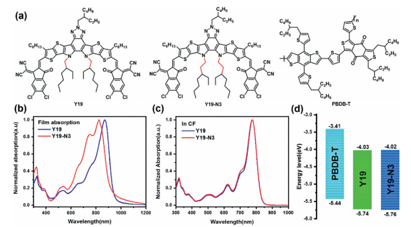
In Fig. 1a, we can easily see that the backbone of alkyl chains on the two pyrrole rings of Y19-N3 has one more carbon atom than that of Y19 and their branching point is transferred to the 3rd-position to be far away from the fused core. Owing to the distortion of the pyrrole rings and the tapered distribution of their attached alkyl chains in 3D configuration, this design can decrease the repulsion between the cores, thereby promoting the cores-to-cores alignment and causing changes in molecular aggregation patterns [11, 39]. As a result, Y19-N3 in film state shows a different absorption from Y19 in the Fig. 1b as its main absorption peak blueshifts 42 nm. However, this change differs from that of Y6 to N3 with only a slight redshift in the absorption, indicating a greater effect of the 3rd-position branching on molecular stacking of Y19-N3. The absorption of Y19-N3 in CF is shown in Fig. 1c. Y19-N3 has the same absorption as Y19 and the main absorption peaks are estimated at 775 nm. The electrochemical properties of Y19-N3 are investigated by measuring cyclic voltammetry (CV) measurement. The CV curves and related data are shown in Figs. S8 and S9 (Supporting information) and Fig. 1d. According to the equation EHOMO/LUMO = -(4.80-E1/2, Fc/FC++Eonest, ox/red), the highest occupied molecular orbital (HOMO) level and the lowest unoccupied molecular orbital (LUMO) level of Y19-N3 are calculated as -5.76 eV and -4.02 eV, respectively. The experimental values of energy levels for Y19-N3 are almost identical to those of Y19 (-5.74 eV and -4.03 eV, respectively), which means that the side-chain modification minimally affects the electrochemical properties of acceptors.

|
Download:
|
| Fig. 1. (a) Molecular structures of Y19, Y19-N3 and PBDB-T. (b) The normalized absorption spectra of Y19 and Y19-N3 in film states. (c) The normalized absorption spectra of Y19 and Y19-N3 in CF. (d) energy levels of PBDB-T, Y19 and Y19-N3. | |
In order to provide information for selecting suitable solvents, Fig. S6 (Supporting information) shows the absorption curves of Y19-N3 in CB and CF with the concentration of 10−5 mol/L. Their absorption coefficients are obtained and the related data are listed in Table S1 (Supporting information). Compared to CF, CB enables Y19-N3 to exhibit the slightly 4 nm-blueshift but significantly broadened and enhanced ultraviolet-visible absorption spectrum. The absorption coefficient of Y19-N3 in CB is measured as 1.66 × 10⁵ L mol−1 cm−1 at 768 nm, which is higher than its counterpart in CF (1.49 × 10⁵ L mol−1 cm−1 at 775 nm). There have been several studies highlighting the inherent reason that CB, as an aromatic solvent, can produce the additional molecules–solvent π−π interactions [40]. Therefore, it can be argued that Y19-N3 dissolved in CB tends to obtain more excellent features in absorption and intramolecular charge transfer.
In this study, PBDB-T is selected as electron donor after considering the following points: (i) it has been commercialized; (ii) compared to PM6, it is much cheaper and (iii) its absorption and energy levels can well match with Y19 and Y19-N3.
In order to explore the photovoltaic properties of Y19-N3 and Y19, solution-processed OSCs based on PBDB-T: Y19-N3 and PBDB-T: Y19 are fabricated with the inverted structure of ITO/ZnO/active layer/MoO3/Ag. According to our previous work [41], common solvent composed of CF and DIO (0.5%, v/v) are employed to cast device and the D/A ratio of 1:1 (w/w) and thermal annealing (TA) at 110 ℃ for 5 min are used as the first optimization. This optimized condition is consistent with the experimental result of Tables S4 and S5 (Supporting information). As shown in Table S2 (Supporting information), under the same optimized condition, the PBDB-T: Y19-based devices achieve a PCE of 11.22% with Voc of 0.73 V, Jsc of 23.95 mA/cm2 and FF of 0.64. In contrast, an improved PCE of 12.86% is obtained in the PBDB-T: Y19-N3 based devices with an increased Voc of 0.75 V, Jsc of 24.44 mA/cm2, and FF of 0.70. Among these, the improvement of FF is considered as the dominant factor for improving photovoltaic performance.
As depicted in Fig. 2a, in addition to the above common solvent, binary solvent of CB/DIO and ternary solvent of CF/CB/DIO are also applied in the PBDB-T: Y19-N3-based devices, aimed at further improving the device performance. A series of the optimized devices are constructed by applying the above optimized conditions and varying the volume ratio of CF and CB (CF/CB) in order of 1:0, 3:1, 1:1, 1:3, and 0:1 with invariable DIO of 0.5% (v/v). The related device data are listed in Table 1 and Table S3 (Supporting information). Compared to common solvent, binary solvent of CB/DIO allows the PBDB-T: Y19-N3-based devices an improved PCE of 13.41% with the increased Voc of 0.79 V and FF of 0.71 as well as the slightly decreased Jsc of 24.13 mA/cm2. Meanwhile, voltage loss (Eloss) of device is obtained according to the equation: Eloss=Eg-qVoc, where Eg denoting the optical bandgap of acceptor is estimated to be 1.35 eV. It should be noted that CB/DIO-treated devices have a lower Eloss of 0.57 V than 0.60 V of CF/DIO-treated devices. When CF/CB ratio is 1:3, OSCs treated with a ternary solvent exhibit a higher PCE of 13.44% with Voc of 0.78 V, Jsc of 24.40 mA/cm2 and FF of 0.71 as well as the low Eloss of 0.57 V.

|
Download:
|
| Fig. 2. (a) Structure diagram of the PBDB-T: Y19-N3 based devices. (b) The optimized PCE versus the ratio of CF and CB. (c) Voc and Eloss versus the ratio of CF and CB. (d) Jsc and FF versus the ratio of CF and CB with DIO of 0.5%. | |
|
|
Table 1 Photovoltaic parameters of the PBDB-T: Y19-N3 based devices processed by different solvents. |

In order to analyze the specific effects of the different processing solvent on the photovoltaic performance of the PBDB-T: Y19-N3-based devices, the varying trends of the optimized PCE, Voc and Eloss as well as Jsc and FF depending on the volume ratio of CF and CB are shown separately in the Figs. 2b–d. The volume ratio of CF and CB reflects the volume fraction of CB in the total volume of CF and CB. For example, the volume ratio of 1:3 means that volume of CB is 75% of the total volume of CF and CB. Although there are no clear formulas to quantify the relationships between these device parameters and the volume fraction of CB, it is necessary to add trends in order to provide some direct evidence for solvent effects. Notably, in the Fig. 2c, Voc increases linearly with the increasing content of CB while Eloss has a linear decrease. In the Fig. 2d, it can be observed that when the volume ratio is about 1:3, Jsc and FF are simultaneously high. In accordance with this, PCE shows a maximum value at 1:3 of CF: CB in the Fig. 2b. And near this maximum, the small fluctuation of volume ratio has little effects on PCE. Therefore, this indicates that CF and CB with a volume ratio of 1:3 make the PBDB-T: Y19-N3 based OSCs high photovoltaic performance.
To obtain the best PCE, the DIO content is adjusted from 0.5% to 0.3%, 0.8%, 1% and 1.5% before the spin-coating process. As shown in the Table S6 (Supporting information), the optimal PCE of 13.77% is obtained with Voc of 0.78 V, Jsc of 24.46 mA/cm2 and FF of 0.72 when DIO is 0.8%. Therefore, a ternary solvent comprising CF/CB of 1:3 and 0.8% DIO can be as the desired solvent system for processing the PBDB-T/Y19-N3 film. Besides, the as-cast device is also fabricated to make a reference. It is shown in Table 2 that the as-cast devices achieve a PCE of 11.83% with Voc of 0.75 V, Jsc of 24.26 mA/cm2 and FF of 0.65.
|
|
Table 2 Detailed photovoltaic parameters and processing conditions of the as-cast and optimal PBDB-T: Y19-N3 based devices under the illumination of AM 1.5 G (100 mW/cm2). |

In order to investigate a high Jsc, external quantum efficiency (EQE) of the as-cast and optimal PBDB-T/Y19-N3 film are tested and analyzed. In Fig. S10b (Supporting information), both two type of devices show a pair of distinct photoresponse peaks over 70% EQE from 530 nm to 870 nm. This wide range is consistent with the main absorption peaks from the absorption spectrum of the PBDB-T: Y19-N3 blend film in Fig. S7 (Supporting information). The two maximal EQE peaks of the optimal devices are measured as 80.14% at 580 nm and 77.82% at 820 nm, respectively. In contrast, the as-cast devices achieve a slight improvement with an 81.58% EQE peak at 590 nm and a 79.29% EQE peak at 820 nm, respectively. The calculated integral Jsc from EQE curves are 24.42 mA/cm2 for the optimal devices and 24.25 mA/cm2 for the as-cast, respectively, which is almost identical to the Jsc data in Table 2 from J-V measurements.
The fitting curves between the photocurrent density (Jph) and the effective voltage (Veff) are depicted in Fig. S10c (Supporting information), aiming to clarify exciton dissociation and charge collection. Photocurrent density is recognized as the difference between current density under illumination (JI) and the dark current density (JD), i.e., Jph = JI - JD. The effective voltage is promised as the difference between the voltage at Jph = 0 (V0) and the applied voltage (VA), i.e., Veff = V0 - VA. A comprehensive evaluation parameter (η) is calculated to quantify the changing processes of exciton and charge according to the defined formula: η = Psc/Jsat, where Jsat means the saturation photocurrent density at Veff = 2.65 V. For the as-cast device, the η value reaches 95.1% with Jsat of 25.52 mA/cm2. In contrast, the use of DIO and TA slightly improve this parameter to 96.3% with Jsat of 25.40 mA/cm2, revealing slightly higher exciton dissociation and charge collection in the optimal devices.
In order to study the charge recombination process, the relationships of Jsc versus Plight and Voc versus InPlight are explored, respectively. In Fig. S11b (Supporting information), the slope of Voc versus InPlight is employed to discriminate bimolecular recombination and trap-assisted recombination, depending on whether the value of slope is close to KBT/q or 2KBT/q. Both types of devices have a similar slope value close to 1, which means that bimolecular recombination is clearly dominant in all the PBDB-T: Y19-N3-based devices. Besides, the optimal devices exhibit a slightly larger slope of 1.16 KBT/q than 1.10 KBT/q of the as-cast devices, confirming a higher proportion of trap-assisted recombination in the optimal devices. In general, the closer exponent existing in the correlation of Jsc∝Plightα is to 1, the weaker charge recombination in the PBDB-T/Y19-N3 film. As shown in the Fig. S11a (Supporting information), the optimal devices possess a relative exponent of 0.993 closer to 1 compared to the as-cast devices (0.917), indicating its relatively little charge recombination in the high-efficient charge transport process.
To verify the difference in FF between the optimal and as-cast devices, the charge mobilities are measured by the space-charge-limited current (SCLC) [42]. The J1/2-V data on electron and hole mobilities are exported from the electron-only devices with the structure of ITO/ZnO/PBDB-T: Y19-N3/PDINO/Al and the hole-only devices with the structure of ITO/PEDOT: PSS/PBDB-T: Y19-N3/MoO3/Ag, respectively. These related curves are plotted in the Figs. S11c and d (Supporting information). For the as-cast devices, its electron mobility (μe) and hole mobility (μh) are estimated to be 3.30 × 10⁻⁴ cm2 V−1 s-1 and 5.77 × 10⁻⁴ cm2 V−1 s-1, respectively. After using 0.8% DIO and TA to improve the morphology of the blend film, the corresponding two values increase to 5.46 × 10⁻⁴ cm2 V−1 s−1 and 6.23 × 10⁻⁴ cm2 V−1 s-1 for optimal devices. Meanwhile, the μh to μe ratio decreases from 1.75 of the as-cast devices to 1.14 of the optimal devices, which tends to be more balanced after ternary solvent treatment. Generally, the high and balanced charge mobilities are related to the low charge recombination in the photoactive layer, which leads to higher FF of 0.72 in optimal devices.
To explore the active-layer morphology, the height images and phase images of the as-cast and optimal blend films were measured by atomic force microscopy (AFM). As shown in the Figs. S12a and c (Supporting information), both films exhibit a smooth surface. The mean-square surface roughness (Rq) of the as-cast film is 1.28 nm. In contrast, the optimal films have a smaller Rq of 1.16 nm. Consistent with this, it is observed from the corresponding phase images in the Figs. S12b and d (Supporting information) that the optimal films maintain better nanoscale phase separation and larger fibrous regions compared to the as-cast film. The optimal devices show more desired morphological characteristics, which is conducive to exciton dissociation and charge transportation, and thus relatively higher photovoltaic performance.
In summary, by applying the 3rd-position branching strategy to Y19, a new NFA Y19-N3 is designed and synthesized with same conjugated skeleton and similar LUMO energy level but broaden absorption. The main absorption peak of Y19-N3 in film state exhibits a blueshift of 42 nm compared to that of Y19. When CF and 0.5% DIO is applied to spin-coating active layer, the PBDB-T: Y19-N3-based devices give a higher PCE of 12.86% than 11.22% of PBDB-T: Y19-based devices owing to the increased Voc (0.75 V) and Jsc (24.44 mA/cm2) and the significantly improved FF (0.70). Ternary solvent strategy is adopted to optimize PBDB-T: Y19-N3-based OSCs. Then an excellent PCE of 13.77% is obtained with the further increased Voc of 0.78 V and FF of 0.72 as well as the high Jsc of 24.46 mA/cm2. This work demonstrates that the 3rd-position branching of 3-ethylheptyls is important in improving photovoltaic properties of the chlorinated NFA Y19. And it also provides advice on how to further improve device performance by adjusting the processing solvent.
Declaration of competing interestThe authors report no declarations of interest.
AcknowledgmentsThis work was supported by the Fundamental Research Funds for the Central Universities of Central South University (No. 2019zzts443), the National Key Research and Development Program of China (No. 2017YFA0206600), and the National Natural Science Foundation of China (No. 21875286).
Appendix C. Supplementary dataSupplementary material related to this article can be found, in the online version, at doi:https://doi.org/10.1016/j.cclet.2020.10.042.
| [1] |
J.O. Jaber, O. Badran, N. Abushikhah, Clean Technol. Environ. Policy 6 (2004) 174-186. |
| [2] |
A. Bonakdar, M. Rezaei, E. Dexheimer, H. Mohseni, Proc. SPIE 9547 (2015) 954725. |
| [3] |
X. Zhang, C. Hagglund, E.M.J. Johansson, Energy Environ. Sci. 10 (2017) 216-224. DOI:10.1039/C6EE02824A |
| [4] |
C.J. Brabec, S. Gowrisanker, J.J.M. Halls, et al., Adv. Mater. 22 (2010) 3839-3856. DOI:10.1002/adma.200903697 |
| [5] |
G. Yu, J. Gao, J.C. Hummelen, F. Wudl, A.J. Heeger, Science 270 (1995) 1789-1791. DOI:10.1126/science.270.5243.1789 |
| [6] |
Q. Liu, Y. Jiang, K. Jin, et al., Sci. Bull. 65 (2020) 272-275. DOI:10.1016/j.scib.2020.01.001 |
| [7] |
T. Xu, L. Yu, Mater. Today 17 (2014) 11-15. DOI:10.1016/j.mattod.2013.12.005 |
| [8] |
B. Fan, X. Du, F. Liu, et al., Nat. Energy 3 (2018) 1051-1058. DOI:10.1038/s41560-018-0263-4 |
| [9] |
Z. Zhou, W. Liu, G. Zhou, et al., Adv. Mater. 32 (2020) 1906324. |
| [10] |
L. Feng, J. Yuan, Z. Zhang, et al., ACS Appl. Mater. Interfaces 9 (2017) 31985-31992. DOI:10.1021/acsami.7b10995 |
| [11] |
J. Yuan, Y. Zhang, L. Zhou, et al., Joule 3 (2019) 1140-1151. DOI:10.1016/j.joule.2019.01.004 |
| [12] |
R. Qin, D. Wang, G. Zhou, et al., J. Mater. Chem. 7 (2019) 27632-27639. DOI:10.1039/C9TA11285E |
| [13] |
J. Yuan, Y. Zhang, L. Zhou, et al., Adv. Mater. 31 (2019) 1807577. DOI:10.1002/adma.201807577 |
| [14] |
L. Zhan, S. Li, T. Lau, et al., Energy Environ. Sci. 13 (2020) 635-645. DOI:10.1039/C9EE03710A |
| [15] |
Y. Cui, H. Yao, L. Hong, et al., Natl. Sci. Rev. (2019) 1239-1246. |
| [16] |
B. Kan, X. Chen, K. Gao, et al., Nano Energy 67 (2020) 104209. DOI:10.1016/j.nanoen.2019.104209 |
| [17] |
F. Zhao, D. He, J. Xin, et al., Sci. China-Chem. 62 (2019) 790-796. DOI:10.1007/s11426-019-9453-7 |
| [18] |
K. Jiang, Q. Wei, J.Y.L. Lai, et al., Joule 3 (2019) 3020-3033. DOI:10.1016/j.joule.2019.09.010 |
| [19] |
M. Chen, D. Liu, W. Li, et al., ACS Appl. Mater. Interfaces 11 (2019) 26194-26203. DOI:10.1021/acsami.9b07317 |
| [20] |
H. Yao, Y. Cui, R. Yu, et al., Angew. Chem. 56 (2017) 3045-3049. DOI:10.1002/anie.201610944 |
| [21] |
F. Zhao, S. Dai, Y. Wu, et al., Adv. Mater. 29 (2017) 700144. |
| [22] |
S. Liu, J. Yuan, W. Deng, et al., Nat. Photonics 14 (2020) 300-305. |
| [23] |
M. Luo, C. Zhu, J. Yuan, et al., Chin. Chem. Lett. 30 (2019) 2343-2346. DOI:10.1016/j.cclet.2019.07.023 |
| [24] |
Y. Zhang, H. Yao, S. Zhang, et al., Sci. China-Chem. 61 (2018) 1328-1337. DOI:10.1007/s11426-018-9260-2 |
| [25] |
Y. Cui, C. Yang, H. Yao, et al., Adv. Mater. 29 (2017) 1703080. |
| [26] |
M.L. Tang, J.H. Oh, A.D. Reichardt, Z. Bao, J. Am. Chem. Soc. 131 (2009) 3733-3740. DOI:10.1021/ja809045s |
| [27] |
F. Yang, C. Li, W. Lai, et al., Mat. Chem. Front. 1 (2017) 1389-1395. DOI:10.1039/C7QM00025A |
| [28] |
T. Aernouts, T. Aleksandrov, C. Girotto, J. Genoe, J. Poortmans, et al., Appl. Phys. Lett. 92 (2008) 033306. |
| [29] |
I. Burguesceballos, F. Machui, J. Min, et al., Adv. Funct. Mater. 24 (2014) 1449-1457. DOI:10.1002/adfm.201301509 |
| [30] |
Y. Cui, H. Yao, J. Zhang, et al., Nat. Commun. 10 (2019) 2515. |
| [31] |
Q. Fan, W. Su, Y. Wang, et al., Sci. China-Chem. 61 (2018) 531-537. DOI:10.1007/s11426-017-9199-1 |
| [32] |
B. Kan, H. Feng, H. Yao, et al., Sci. China-Chem. 61 (2018) 1307-1313. DOI:10.1007/s11426-018-9334-9 |
| [33] |
H. Lai, Q. Zhao, Z. Chen, et al., Joule 4 (2020) 688-700. DOI:10.1016/j.joule.2020.02.004 |
| [34] |
B.R. Aich, J. Lu, S. Beaupre, M. Leclerc, Y. Tao, Org. Electron. 13 (2012) 1736-1741. DOI:10.1016/j.orgel.2012.05.001 |
| [35] |
W. Cai, P. Liu, Y. Jin, et al., Adv. Sci. 2 (2015) 1500095. |
| [36] |
S.H. Eom, H. Park, S.H. Mujawar, et al., Org. Electron. 11 (2010) 1516-1522. DOI:10.1016/j.orgel.2010.06.007 |
| [37] |
L. Ye, S. Zhang, W. Ma, et al., Adv. Mater. 24 (2012) 6335-6341. DOI:10.1002/adma.201202855 |
| [38] |
D.T. Duong, B. Walker, J. Lin, et al., J. Polym. Sci. Pt. B-Polym. Phys. 50 (2012) 1405-1413. DOI:10.1002/polb.23153 |
| [39] |
W. Li, M. Chen, J. Cai, et al., Joule 3 (2019) 819-833. DOI:10.1016/j.joule.2018.11.023 |
| [40] |
L. Zuo, X. Hu, T. Ye, et al., J. Phys. Chem. C 116 (2012) 16893-16900. DOI:10.1021/jp3049444 |
| [41] |
M. Luo, L. Zhou, J. Yuan, et al., J. Energ. Chem. 42 (2020) 169-173. DOI:10.1016/j.jechem.2019.07.002 |
| [42] |
T. Chu, O. Song, et al., Appl. Phys. Lett. 90 (2007) 203512. |