 2021, Vol. 32


b State Key Laboratory of Chemical Resource Engineering, College of Chemistry, Beijing University of Chemical Technology, Beijing 100871, China
All solid-state batteries (ASSBs) have arouse worldwide attention and discussion due to the advantages of potentially high energy densities and high safety [1, 2]. Li metal was selected as the anode material for ASSBs on the account of the high theoretical specific capacity of 3860 mAh/g and the low reduction potential of -3.04 V versus standard hydrogen electrode [3-5]. During cycling, the uncontrolled Li dendrite growth may pierce the separator/electrolyte membrane and leads to severe safety issues [6-8]. Thus the solid state electrolytes (SSEs) need be with high mechanical strength to physically suppress the growth of Li dendrites [9-11]. On the other hand, the interface between the SSE and the cathode particles is often with poor contact, which is ascribed to the point-to-point contact of the solid-solid interface [12], causing large interfacial resistance and limited transport kinetics of Li+ ions at the interface [13-16]. Thus, a promising SSE should possess both the high ionic conductivity of the bulk and the stable interfaces with electrodes [17-19]. For anode side, SSE is required to possess high mechanical strength that prevents lithium (Li) dendrites from penetrating. In the meantime, SSE also needs to fulfill the requirements of low interface resistance and high electrochemical stability on the cathode side. The out-sync requirements for the interface properties with anode and cathode are difficult to fulfill solely by the ceramic electrolyte or polymer electrolyte, which largely hinders the successful deployment of ASSBs in practical applications.
Therefore, an asymmetric double-layer design of SSE is a fascinating route to overcome these problems, where the flexible layer reduces the interfacial resistance while the high-modulus layer prevents potential dendrite penetration and electrode structure fragmentation. Wu and co-workers proposed a composite electrolyte where ionic liquids were introduced to form a viscoelastic interface that can maintain good interfacial connection and promote the Li+ transport kinetics effectively [20]. Although ionic liquids are non-inflammable and compatible with Li metal anode [21], they are expensive and difficult to prepare, which can hardly be utilized in large-scale applications. Besides, some asymmetric solid electrolytes were proposed usually including a ceramic layer for suppressing Li metal dendrite growth and a soft polymer layer for cathode contacting [22]. Inspired by these pioneering works, we consider a double layer polymer electrolyte design with an organic/inorganic mixed layer toward Li metal anode will be more efficient than the rigid ceramic electrolyte layer, given the facts that Li dendrites could also grow along the grain boundaries of the ceramics at high current densities [23, 24].
In this work, we propose a novel composite electrolyte with asymmetric double-layer membranes. The materials design strategy is described as follows: (ⅰ) hexagonal boron nitride particles (hBN) were added as inorganic fillers into polyethylene oxide (PEO) for Li metal anode. The PEO-hBN layer exhibits high mechanical strength that are able to significantly suppress Li dendrites growth, where the hBN can also function as a Lewis acid to promote the Li+ ionic conductivity of the layer [25, 26]. (ⅱ) Polypropylene carbonate (PPC) was chosen for the cathode side. PPC with the similar structure to carbonate solvents demonstrates excellent compatibility with lithium salts. The PPC layer that prepared by proper proportion of PPC and LiTFSI is viscous, and can make good interfacial connection between cathode particles and electrolytes thus provide sufficient contacting area for Li+ transport. The double-layer composite electrolyte shows good thermal and chemical stability, wide electrochemical window and high ionic conductivity. A solid Li||LFP battery with this doublelayer composite electrolyte performs high discharge capacity and stable cycling at room temperature.
The asymmetric double-layer composite electrolyte of PEO-hBN/PPC (PBP) was prepared by a solution-casting method. PEO (molecular weight of ~600,000, 99%, Aladdin) and LiTFSI (99%, Aladdin) were dissolved in acetonitrile (99.8%, Aladdin) with a molar ratio of 12. Then the solution was stirred rapidly for 4 h and sonicated for 30 min to get a homogeneous dispersion. hBN (99.9%, Aladdin) was added in the above mixture and the weight ratio of hBN/PEO was 4/6 (referred as 40% hBN). The resulting mixture was poured into a polytetrafluoroethylene mold and dried in an Ar-filled glove box (with water and oxygen contents both below 1.0 ppm). After entirely evaporation of solvent, the PEO-hBN film was formed in the mold. Thereafter, PPC (molecular weight of ~50,000, Aldrich) and LiTFSI with a molar ratio of 0.02 were mixed homogeneously in N-methyl pyrrolidone (NMP, AR, Aladdin), then the viscous solution was poured on the surface of previously dried PEO-hBN film. After that it was dried in a vacuum oven at 70 ℃ until the solvent was completely removed. The free-standing electrolyte film can be then peeled off from the mold.
The morphology of the electrolyte membrane was acquired on the scanning electron microscope (SEM, Hitachi S-4800). Tensile tests were performed by using an Instron model 5966 universal material testing system. The specimens were made into Dumbbell-shaped (8 mm width ×0.5 mm thick; gauge length 20 mm). X-ray diffraction (XRD) was performed on a PANalytical X-ray diffractometer with Cu Kα radiation (λ =1.54178 Å) over a 2θ range of 5°-80°. The Fourier transform infrared (FTIR) spectra were obtained by a FTIR spectrometer (ThermoFisher) form 400 cm-1 to 4000 cm-1. X-ray photoelectron spectroscopy (XPS) was conducted on AXIS Supra using 150 W Al radiation. Thermogravimetric analysis (TGA) was performed on Q600 SDT analyzer, and the samples were heated within the temperature range from 25 ℃ to 700 ℃ at a heating ramp rate of 5 ℃/min under N2 atmosphere.
Linear sweep voltammetry (LSV) was performed on an electrochemical workstation (CHI 660B, CHI Inc., Shanghai) with a scan rate of 5 mV/s by sandwiching the asymmetrical composite electrolyte between Li metal counter electrode and the stainless steel working electrode. Electrochemical impedance spectroscopy (EIS) was collected with a symmetric cell configuration which comprises two identical stainless steel foils and the composite electrolyte was placed in between. The ionic conductivity (σ) of the composite electrolyte can be calculated by the equation as follows [27-29]:

|
(1) |
where d is the thickness of the electrolyte membrane, A represents the cross-section area of stainless steel electrode, and Rb corresponds to the resistance of the measured electrolyte.
The activation energy for Li+ migration in the composite electrolyte can be estimated by the Arrhenius equation [30, 31]:

|
(2) |
where σ0 represents the initial ionic conductivity of the composite electrolyte, Ea refers to the activation energy of Li+ conduction, R is the Boltzmann constant and T is the absolute temperature.
Chronoamperometry test was conducted with the symmetrical Li metal cell configuration of Li||Li at a voltage polarization of 20 mV. EIS measurement was also performed before and after polarization. Li ion transference number (t+) was calculated by the following equation [31].
|
(3) |
Where ΔV refers to the voltage polarization applied (20 mV), I0 and Is are the initial and steady state current, Rb0 and Rbs correspond to the bulk resistance of the electrolyte before and after polarization, Rl0 and Rls stand for the interfacial resistances of the Li metal electrode and electrolyte before and after polarization.
For full cell measurement, the cathode slurry was prepared by mixing LiFePO4/C powder (LFP), carbon black and poly(vinylidene fluoride) (PVDF) with a mass ratio of 75:15:10, after that it was cast onto the aluminum foil and dried at 90 ℃ for 1 h and then dried in vacuum oven at 120 ℃ for 12 h. The mass loading of LFP is about 4 mg/cm2. The CR2032-type cells were assembled using LFP as cathode and Li metal as anode in an Ar-filled glove box then aged for 20 h before the electrochemical measurements. Charge-discharge tests were conducted at 25 ℃ at 0.1 C (1 C = 170mAh/g) with voltage ranging from 2.5 V to 4.2 V by a Land CT2001A battery testing system (Wuhan Land Electronic Co., Ltd., China).
The schematic diagram and preparation of the composite electrolyte (PBP) was demonstrated in Fig. 1. The PBP electrolyte was prepared by solution-casting method. The mixture of PEO and hBN was poured into a polytetrafluoroethylene mold to get a PEO-hBN film, after that the solution with PPC was poured on the surface of the PEO-hBN film and dried in an Ar-filled glove box. The PBP electrolyte has a double layered structure, in which the PEO layer modified with hBN on the Li-anode side, and a PPC layer was specifically designed to have a soft contact with the cathode active materials.

|
Download:
|
| Fig. 1. (a) Schematic diagram of PBP composite electrolyte by the solution-casting method. (b) Schematic diagram of PBP composite electrolyte with asymmetric double layered structure, in which the PPC layer can provide intimate contact with cathode while the hBN modified PEO layer with high mechanical stress suppresses Li dendrite growth. (c, d) The comparisons with the electrolytes of single layer. | |
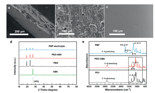
Fig. 2a showed the cross-sectional scanning electron microscopy (SEM) images of PBP electrolyte, indicating the successful fabrication of the double-layer structure. The surface morphology of PEO-hBN layer and PPC layer were displayed in Figs. 2b and c, respectively. It can be concluded that the PEO-hBN layer is porous where the PEO-Li salt and hBN particles are fully intermingled. The robust PEO-hBN layer provides high mechanical strength against Li metal to suppress Li dendritic growth. In contrast, the surface of PPC layer is smoother than that of PEO-hBN layer, which can provide intimate contact with electrode and construct effective conductive pathways for charge transfer [32].

|
Download:
|
| Fig. 2. (a) Cross-sectional SEM image of PBP composite electrolyte. Surface SEM image of (b) PEO-hBN electrolyte and (c) PPC electrolyte. (d) XRD spectra of PBP, PEO-hBN, PEO and hBN. (e) FTIR spectra of PBP, PEO-hBN and PEO electrolytes. | |
X-ray diffraction patterns were collected and the results of PBP, PEO-hBN, PEO and hBN were shown in Fig. 2d. The XRD pattern of hBN matches well with the standard card (ICSD collection code: 98-024-0999), suggesting a hexagonal phase with space group of P63/mmc. The pattern of PEO shows two sharp peaks, indicating the high crystallinity of bare PEO. After adding hBN, the peak intensities of PEO-hBN and PBP samples decrease, which means the crystallinity degrees of PBP and PEO-hBN electrolytes are obviously declined, which confirms the enhanced ionic conductivity of composite electrolytes. XPS was conducted in order to characterize the bonding situation and element composition of PBP electrolyte (Fig. S1 in Supporting information). On the PPC side, the peak around 399.2 eV belongs to TFSI- in the N 1s spectra. On the PEO-hBN side, the two extra peaks around 398.0 and 399.3 eV are attributed to the N in BN and TFSI-, respectively. This also demonstrated that the asymmetric PBP composite electrolyte had different chemical properties towards different electrodes.
FTIR spectroscopy was also recorded to analyze the chemical composition of the PBP electrolyte and the results were shown in Fig. 2e. The composite electrolyte is successfully prepared as the appearance of all typical peaks of PPC, PEO and hBN in the spectra of PBP electrolyte. The absorption peak at 1225 cm-1 can be ascribed to the stretching vibration of C-O-C band. The characteristic absorption band for hBN is due to stretching vibration of B-N at 1241 cm-1. The C=O region of PBP electrolyte is divided into two bands at around 1740 cm-1 (free C=O) and 1712 cm-1 (C = O–Li) owing to the interactions between LiTFSI and PPC matrix [33, 34]. The coordination interaction between Li+ and C=O group in PPC is weaker than that of ether chains in PEO [35, 36], which indicates the enhancement of Li ion transport in PPC segments.
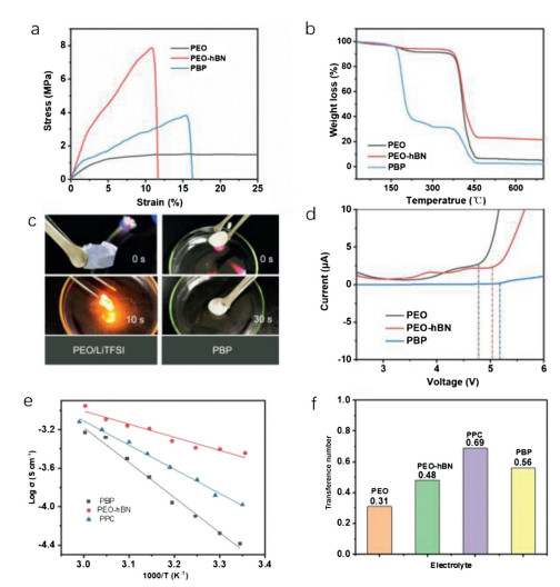
The mechanical properties of PBP composite electrolyte were measured by tensile test and compared with its counterparts (Fig. 3a). The modulus of bare PEO is only 1.0MPa, while the modulus increase to 7.8MPa with the addition of hBN. The PBP composite electrolyte provides an acceptable modulus of 3.8MPa due to the presence of hBN and the flexible PPC. Thermogravimetric (TG) analysis was utilized to evaluate the thermal stability of PBP composite electrolyte (Fig. 3b). Unlike the PEO and PEO-hBN counterparts, the PBP composite electrolyte showed a dramatic weight loss around 200 ℃ due to the decomposition of PPC layer. However, there is still ~25% weight remained after pyrolysis at ~450 ℃ which can be attribute to the presence of hBN [37]. To further prove the thermal and oxidation stability of the composite electrolyte, the PBP and PEO/LiTFSI electrolyte was ignited under the same condition. As can be seen in Fig. 3c, PBP membrane was nonflammable due to the fascinating burning property of PPC and hBN [38]. In sharp contrast, the PEO/LiTFSI electrolyte was rapidly ignited with obvious flame.

|
Download:
|
| Fig. 3. (a) Stress–strain curves, (b) TG curves, (d) LSV plots and (g) lithium ion transference numbers of PEO, PEO-hBN and PBP electrolytes. (c) Photo images of flame test on a PEO/LiTFSI film and a PBP film. (e) Arrhenius plots of PEO-hBN and PBP electrolytes ranging from 25 ℃ to 60 ℃. (f) The Li+ ion transference number of PEO, PEO-hBN, PPC and PBP. | |
Fig. 3d demonstrated the linear scanning cyclic voltammetry (LSV) of different polymer electrolytes. The decomposition of PEO at potential exceeding 4.83V vs. Li+/Li during cycling process limits its compatibility with cathode materials, that some cathode materials with high charge/discharge plateaus like LiCoO2, LiNi1-x-yCoxMnyO2, etc. cannot be used in the system which largely reduced its energy density [39]. On the contrary, the PBP composite electrolyte membrane showed a wide electrochemical window of 5.17V, which means that the PBP composite electrolyte can fully meet the chemical stability requirements of high-voltage lithium batteries. The enhancement in electrochemical stability of PBP electrolyte can be deduced as the formation of polyether-hBN complexes [40].
The ionic conductivity values of the PEO-hBN, PPC and the PBP membrane were measure by Electrochemical impedance spectroscopy (EIS) at various temperatures ranging from 25 ℃ to 60 ℃ (Fig. 3e and Fig. S2 in Supporting information). The PEO–hBN, PPC and PBP composite electrolyte possess the ionic conductivity of 2.72 ×10⁻⁵, 3.12 ×10⁻⁴ and 6.11 ×10⁻⁴ S/cm at 25 ℃, respectively. It is reported that pure PEO electrolyte shows the ionic conductivity of 10-7 S/cm at 25 ℃ [41]. The PBP electrolyte membrane has the highest ionic conductivity among them, which can be attributed to two aspects: (1) The electrophilicity of boron atoms in hBN can induce Lewis acid-base interactions between the hBN particles and the PEO chains, hence promote the dissociation of Li salts as well as ionic conductivity [42, 43]. (2) The introduction of PPC layer has enhanced the ion transport capacity of PBP, as the C=O groups in PPC enable the migration of Li+ faster than that coordination of ether O groups in PEO [44]. Meanwhile, we speculate that the smaller molecules of LiTFSI embedded in the polymer chains, and the dipole moment of carbonate group in the main chain of PPC is strong enough to dissociate LiTFSI salt and interact with Li+ [44]. According to Arrhenius equation [45], the activation energies of PEO-hBN, PPC and PBP were 0.67, 0.38 and 0.27eV, respectively, undoubtedly confirmed the synergetic effect between PEO-hBN and PPC layers. Li+ ion transference number is regarded as an important index to evaluate the Li-ion transport capability of electrolytes. The double layer PBP membrane possesses a Li+ ion transference number (t+) as high as 0.56, which is higher than PEO-hBN (0.48) and PEO (0.31), but lower than PPC (0.69) (Fig. 3g and Fig. S3 in Supporting information). The addition of hBN in polymer electrolyte has effectively enhanced Li+ ion transference number by attracting the TFSI anions in electrolyte [46, 47]. The high t+ of PBP reflects effective transportation of Li ions, which is beneficial for inhibiting of the formation of space charge layer and hence suppress dendritic Li deposition [48]. The t+ of PPC is the highest in the electrolyte. It confirms our above hypothesis that the Li+ ion transference number can be promoted when a certain concentration of LiTFSI salt is embedded into the PPC chains [44]. In conclusion, the excellent performance of PBP comes from the mechanical properties of PEO and the high Li+ ion transference number of PPC, respectively. PEO-hBN and PPC are successfully coupled in the asymmetric composite electrolyte to implement the value-added benefit of 1 + 1 > 2, and prove the innovation of our work.
Li||Li symmetric cells with PBP, PEO-hBN and PEO membranes as electrolyte were assembled to investigate the interface stability between Li metal anode and the polymer electrolytes under a fixed current density of 0.1 mA/cm2. The overpotential of Li|PBP|Li cell was 0.13 V and quite stable even after 1000 h repeated Li plating/stripping (Fig. 4a). No sign of internal short circuit can be observed throughout the process. In contrast, the overpotential of Li|PEO-hBN|Li cell was higher as 0.28 V for around 500 h. (Fig. S4 in Supporting information). The most serious situation happened with PEO electrolyte that short circuit occurred within 164 h in the Li||Li symmetrical cell evaluation. The surface morphology of Li-metal anode after 300 h cycling was acquired by SEM. For Li metal anode with PEO, dendrites can be observed clearly on the surface (Fig. 4b). However, for Li metal anode with PBP (Fig. 4c) and PEO-hBN (Fig. S5 in Supporting information), the surface is smooth without any obvious dendrite formation. The morphology comparison indicates that the introduction of hBN into PEO electrolyte can effectively suppress dendrite growth, and the PBP composite electrolyte which has hBN modified PEO layer exhibits a high interfacial stability during the lithium plating/stripping process. XPS was further utilized to probe the chemical composition on lithium metal surface after cycling for 300 h. For the cell with PBP as electrolyte, the peak around 399.0 eV belongs to the N in TFSI anions. [48] The signals of Li3N (397.9 eV), LiF (688.6 eV), Li2SO3 (168.6 eV for 2p3/2, 169.9 eV for 2p1/2) were collected on the Li-metal surface (Figs. 4d–g), which can be ascribed to the reaction of LiTFSI with Li metal [49, 50]. The small amount of products after cycling indicate the formation of a relatively stable interface.

|
Download:
|
| Fig. 4. (a) Voltage profiles of the Li|PBP|Li symmetric battery. The inset is the magnified curve. Surface SEM images of Li-metal in (b) PEO electrolyte and (c) PBP electrolyte on PEO-hBN side. XPS results of Li-metal surface: (d) C 1s, (e) S 2p, (f) F 1s, (g) N 1s. | |
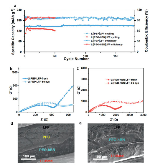
The asymmetrical double layer polymer electrolyte (PBP) was further deployed in all-solid-state lithium metal batteries. Li|PBP|LFP full cells were assembled without any liquid electrolyte to evaluate the cycling performance under the condition of C/10 rate and 25 ℃ (1 C-rate corresponds to 170.0 mA/g), and Li|PEO-hBN|LFP full cells were used as a control. As shown in Fig. 5a, the PBP-based cell delivered a specific capacity of 150.9 mAh/g with a coulombic efficiency of 94.9% after 150 cycles, while only 121.2 mAh/g was obtained for cells with PEO-hBN as electrolyte after 50 cycles. The solid-state batteries with PBP electrolytes show stable cycling and relatively high specific capacities owing to the synergistic effect between PEO-hBN and PPC layer. The polarization voltage was calculated by comparing the plateaus appeared in both the charge and discharge profiles (Fig. S6 in Supporting information). As for the PBP-based cells, which is around 0.3 V at the first cycle. After several cycles, it reduced to a certain value as low as 0.15 V due to the formation of stable interfacial layer, indicating few side reactions and great compatibility at the interface. The charge-transfer resistance of Li|PBP|LFP cell was 623.3 Ω at the first cycle and 812.8 Ω after 50 cycles (Fig. 5b), while the charge-transfer resistance of Li|PEO-hBN|LFP was 1963 Ω initially and 3112 Ω after 50 cycles (Fig. 5c). The relatively small resistance of Li|PBP|LFP was due to the contribution of PPC layer that its flexible characteristic enabled close contact between the electrolyte and the cathode as well as the interfacial compatibility. The cross-section of Li|PBP|LFP and Li|PEO-hBN|LFP after 50 cycles was characterize (Figs. 5d and e). There was no obvious gap across the interfaces of PPC-LFP and clear boundary was observed at the PEO-hBN/PPC interface, indicating great adhesion and high viscoelastic of PPC layer [51]. In addition, there was no Li dendrite formation at the Li|electrolyte interface. However, the cross-section image of Li|PEO|LFP (Fig. S7a in Supporting information) showed obvious gaps at the PEO/LFP interface and Li metal dendrite growth at the Li/PEO interface. Furthermore, without double-layer structure, the bare PEO electrolyte exhibited poor cycling performances and large EIS resistance (Figs. S7b and c in Supporting information). There is, in addition, one further point need to mark that Li|PBP|NCM-811 full cells delivered a high energy density of 621.3 Wh/kg at the first cycles in the wide electrochemical window. After 100 cycles, the energy density was still as high as up to 481.5 Wh/kg at the rate of 1 C (1 C = 195 mA/g) (Fig. S8 in Supporting information). These characterizations undoubtedly demonstrated the successful implementation of our design, where the flexible layer of PPC worked for close contact with the cathode particles and the high-strength layer of PEO-hBN restrained the uneven volume change of the lithium metal anode.

|
Download:
|
| Fig. 5. (a) Cycling performance of Li|PBP|LFP and Li|PEO-hBN|LFP cells at 25 ℃ and 0.1 C-rate. Impedance curves of (b) Li|PBP|LFP and (c) Li|PEO-hBN|LFP cells before and after cycling. The cross-section images of (d) Li|PBP|LFP and (e) Li|PEO-hBN|LFP after cycling 50 cycles at 25 ℃. | |
In summary, we developed an asymmetric double layer design to simultaneously address the contradictory requirements for polymer electrolyte on the Li-metal side and cathode side in all solid state batteries. The asymmetric electrolyte membrane (PBP) comprised of a soft PPC layer that enabled close-contact with cathode and a hBN modified PEO layer that improved the stability toward Li metal anode. Owing to the synergetic effect between hBN, PEO and PPC layer, the asymmetric composite electrolyte demonstrated a wide electrochemical window, high ionic conductivity and great thermal stability. The Li||Li symmetric cells with PBP electrolyte could stable cycle for at least 1000 h without any short circuit. All solid-state battery of Li|PBP|LFP delivered a high specific capacity of 150.9 mAh/g after 150 cycles under the condition of 25 ℃ and 0.1 C. The outstanding full cell performance was attributed to the characteristic asymmetric structure which endowed the stable Li/electrolyte interface and decreased the interfacial charge-transfer resistance on the cathode side. We believe that our work provided a new route for tackling the interfacial problems between polymer electrolyte and electrode, which has a great potential for practical applications in all solid state batteries.
Declaration of competing interestThe authors report no declarations of interest.
AcknowledgmentsThis work was supported by the National Key Research and Development Program of China (Nos. 2016YFB0700604 and 2018YFB1105700), the Natural Science Foundation of Beijing (Nos. 2192018, 2192037), Beijing University of Chemical Technology (Start-up Grant No. buctrc201901), and National Natural Science Foundation of China (Nos. 21673008, 21774090). Binglu Zhao and Luxiang Ma contributed equally to this work.
Appendix A. Supplementary dataSupplementary material related to this article can be found, in the online version, at doi:https://doi.org/10.1016/j.cclet.2020.10.045.
| [1] |
M. Tang, H. Li, E. Wang, et al., Chin. Chem. Lett. 29 (2018) 232-244. DOI:10.1016/j.cclet.2017.09.005 |
| [2] |
S. Xia, X. Wu, Z. Zhang, et al., Chemistry 5 (2019) 753-785. DOI:10.1016/j.chempr.2018.11.013 |
| [3] |
Z. Gao, S. Zhang, Z. Huang, et al., Chin. Chem. Lett. 30 (2019) 525-528. DOI:10.1016/j.cclet.2018.05.016 |
| [4] |
X. Wang, R. Kerr, F. Chen, et al., Adv. Mater. (2020) 1905219. |
| [5] |
L. Chen, W. Li, L.Z. Fan, et al., Adv. Funct. Mater. 29 (2019) 1901047. DOI:10.1002/adfm.201901047 |
| [6] |
X.B. Cheng, R. Zhang, C.Z. Zhao, et al., Chem. Rev. 117 (2017) 10403-10473. DOI:10.1021/acs.chemrev.7b00115 |
| [7] |
A. Mauger, M. Armand, C.M. Julien, et al., J. Power Sources 353 (2017) 333-342. DOI:10.1016/j.jpowsour.2017.04.018 |
| [8] |
M. Zhang, R. Liu, Z. Wang, et al., Chin. Chem. Lett. 31 (2020) 1217-1220. DOI:10.1016/j.cclet.2019.07.055 |
| [9] |
J. Kasemchainan, S. Zekoll, D. Spencer Jolly, et al., Nat. Mater. 18 (2019) 1105-1111. DOI:10.1038/s41563-019-0438-9 |
| [10] |
T. Krauskopf, H. Hartmann, W.G. Zeier, et al., ACS Appl. Mater. Interfaces 11 (2019) 14463-14477. DOI:10.1021/acsami.9b02537 |
| [11] |
J. Ding, R. Xu, C. Yan, et al., Chin. Chem. Lett. 31 (2020) 2339-2342. DOI:10.1016/j.cclet.2020.03.015 |
| [12] |
L.P. Wang, X.D. Zhang, T.S. Wang, et al., Adv. Energy Mater. 8 (2018) 1801528. DOI:10.1002/aenm.201801528 |
| [13] |
K. Fu, Y. Gong, B. Liu, et al., Sci. Adv. 3 (2017) e1601659. DOI:10.1126/sciadv.1601659 |
| [14] |
X. Yu, A. Manthiram, Energy Environ. Sci. 11 (2018) 527-543. DOI:10.1039/C7EE02555F |
| [15] |
Y. Li, X. Chen, A. Dolocan, et al., J. Am. Chem. Soc. 140 (2018) 6448-6455. DOI:10.1021/jacs.8b03106 |
| [16] |
X.B. Cheng, C.Z. Zhao, Y.X. Yao, et al., Chem 5 (2019) 74-96. DOI:10.1016/j.chempr.2018.12.002 |
| [17] |
Z. Zhang, Y. Zhao, S. Chen, et al., J. Mater. Chem. A 5 (2017) 16984-16993. DOI:10.1039/C7TA04320A |
| [18] |
S.S. Chi, Y. Liu, N. Zhao, et al., Energy Storage Mater. 17 (2019) 309-316. DOI:10.1016/j.ensm.2018.07.004 |
| [19] |
J.Y. Liang, X.X. Zeng, X.D. Zhang, et al., J. Am. Chem. Soc. 141 (2019) 9165-9169. DOI:10.1021/jacs.9b03517 |
| [20] |
Q. Ma, X.X. Zeng, J. Yue, et al., Adv. Energy Mater. 9 (2019) 1803854. DOI:10.1002/aenm.201803854 |
| [21] |
X. Gong, L. Li, Chin. Chem. Lett. 28 (2017) 2045-2052. DOI:10.1016/j.cclet.2017.09.051 |
| [22] |
H. Duan, Y.X. Yin, Y. Shi, et al., J. Am. Chem. Soc. 140 (2018) 82-85. DOI:10.1021/jacs.7b10864 |
| [23] |
Y. Ren, Y. Shen, Y. Lin, et al., Electrochem. Commun. 57 (2015) 27-30. DOI:10.1016/j.elecom.2015.05.001 |
| [24] |
R. Sudo, Y. Nakata, K. Ishiguro, et al., Solid State Ion. 262 (2014) 151-154. DOI:10.1016/j.ssi.2013.09.024 |
| [25] |
Q. Weng, X. Wang, X. Wang, et al., Chem. Soc. Rev. 45 (2016) 3989-4012. DOI:10.1039/C5CS00869G |
| [26] |
H. Aydın, S.Ü. Çelik, A. Bozkurt, Solid State Ion. 309 (2017) 71-76. DOI:10.1016/j.ssi.2017.07.004 |
| [27] |
W.J. Hyun, A.C.M. de Moraes, J.M. Lim, et al., ACS Nano 13 (2019) 9664-9672. DOI:10.1021/acsnano.9b04989 |
| [28] |
Z. Zhang, A.R. Gonzalez, K.L. Choy, ACS Appl. Energy Mater. 2 (2019) 7438-7448. DOI:10.1021/acsaem.9b01431 |
| [29] |
D. Zhou, R. Zhou, C. Chen, et al., J. Phys. Chem. B 117 (2013) 7783-7789. DOI:10.1021/jp4021678 |
| [30] |
J. Zhang, J. Zhao, L. Yue, et al., Adv. Energy Mater. 5 (2015) 1501082. DOI:10.1002/aenm.201501082 |
| [31] |
J. Atik, S. Röser, R. Wagner, et al., J. Electrochem. Soc. 167 (2020) 040509. DOI:10.1149/1945-7111/ab72dc |
| [32] |
F. Han, T. Gao, Y. Zhu, et al., Adv. Mater. 27 (2015) 3473-3483. DOI:10.1002/adma.201500180 |
| [33] |
T.H. Cho, M. Tanaka, H. Ohnishi, et al., J. Power Sources 195 (2010) 4272-4277. DOI:10.1016/j.jpowsour.2010.01.018 |
| [34] |
J. Zhang, L. Yue, P. Hu, et al., Sci. Rep. 4 (2014) 6272. |
| [35] |
D. Zhou, R. Zhou, C. Chen, et al., J. Phys. Chem. B 117 (2013) 7783-7789. DOI:10.1021/jp4021678 |
| [36] |
Y. Tominaga, K. Yamazaki, V. Nanthana, J. Electrochem. Soc. 162 (2015) A3133-A3136. DOI:10.1149/2.0211502jes |
| [37] |
P. Ping, D. Kong, J. Zhang, et al., J. Power Sources 398 (2018) 55-66. DOI:10.1016/j.jpowsour.2018.07.044 |
| [38] |
A. Cyriac, S.H. Lee, J.K. Varghese, et al., Green Chem. 13 (2011) 3469-3475. DOI:10.1039/c1gc15722a |
| [39] |
J. Qiu, X. Liu, R. Chen, et al., Adv. Funct. Mater. (2020) 1909392. |
| [40] |
R. Borkowska, A. Reda, A. Zalewska, et al., Electrochim. Acta 46 (2001) 1737-1746. DOI:10.1016/S0013-4686(00)00779-9 |
| [41] |
M.B. Armand, J.M. Chabagno, M.J. Duclot, Poly-ethers As Solid Electrolytes, Fast Ion Transport in Solids. Electrodes and Electrolytes Lake Geneva, WI, USA, 1979, pp. 21-25.
|
| [42] |
F. Croce, G.B. Appetecchi, L. Persi, et al., Nature 394 (1998) 456-458. DOI:10.1038/28818 |
| [43] |
W. Wieczorek, A. Zalewska, D. Raducha, et al., J. Phys. Chem. B 102 (1998) 352-360. DOI:10.1021/jp972727o |
| [44] |
Y. Li, F. Ding, Z.B. Xu i, et al., J. Power Sources 397 (2018) 95-101. DOI:10.1016/j.jpowsour.2018.05.050 |
| [45] |
P. Arora, Z. Zhang, Chem. Rev. 104 (2004) 4419-4462. DOI:10.1021/cr020738u |
| [46] |
J. Shim, H.J. Kim, B.G. Kim, et al., Energy Environ. Sci. 10 (2017) 1911-1916. DOI:10.1039/C7EE01095H |
| [47] |
K.H. Oh, D. Lee, M.J. Choo, et al., ACS Appl. Mater. Interfaces 6 (2014) 7751-7758. DOI:10.1021/am5010317 |
| [48] |
C.Z. Zhao, X.Q. Zhang, X.B. Cheng, et al., Proc. Natl. Acad. Sci. U.S.A. 114 (2017) 11069-11074. DOI:10.1073/pnas.1708489114 |
| [49] |
N.W. Li, Y.X. Yin, J.Y. Li, et al., Adv. Sci. 4 (2017) 1600400. DOI:10.1002/advs.201600400 |
| [50] |
S.Y. Lang, Y. Shi, Y.G. Guo, et al., Angew. Chem. Int. Ed. 55 (2016) 15835-15839. DOI:10.1002/anie.201608730 |
| [51] |
W. Zhou, Z. Wang, Y. Pu, et al., Adv. Mater. 31 (2018) 1805574. |