 2021, Vol. 32


b Hoffmann Institute of Advanced Materials, Shenzhen Polytechnic, Shenzhen 518055, China;
c Renewable Energy Research Group (RERG), Department of Building Services Engineering, The Hong Kong Polytechnic University, Hong Kong, China
With the rapid consumption of fossil energy and the increasing environmental disruption arise from excessive dependence on traditional fuels; researchers are compelled to explore renewable and clean energy through effective strategies. Metal air batteries, fuel cells, and electrolyzed water technology are considered as non-polluted and valuable devices for energy conversion and storage [1-5]. Towards these energy conversion technologies, the key to commercial applications is a set of electrochemical procedures, which mainly involve hydrogen evolution reaction (HER) that can supply hydrogen as a clean energy carrier and oxygen evolution reaction (OER) related to water splitting [6-9]. Oxygen reduction reaction (ORR) that occurs on the cathode of hydrogen-oxygen fuel cell is also one of the most critical reactions [10, 11], when combined with its reverse process (OER), a rechargeable metal-air battery can be assembled [12]. Yet, their low dynamics severely limit the energy conversion efficiency apply in electrochemical devices [13-15]. It is well known that precious metals, for instance Pt, Ir, Ru, and their oxides exhibit exceptional electrochemical properties for the above reactions [16-21]. However, the expensive cost and scarcity of these noble metals on the earth have restricted the commercialization of renewable energy technologies [22-25]. What is more, poor durability and extreme sensitivity to alcohol have become other obstacles in the large-scale practical applications [26-28]. Therefore, to develop multifunctional electrocatalysts with high catalytic efficiency, favorable stability and low cost as substitution remain a significant challenge.
Lately, heteroatoms (N [29], P [30], S [31], B [32])-doped carbon materials as a kind of new type electrocatalyst has attracted more attention owing to their remarkable electrocatalytic performance, higher stability and lower cost. The outstanding electrocatalytic activity of heteroatom-doped carbon materials is mainly accredited to the heteroatoms taking the place of certain carbon atoms in the sp2 lattice of graphite carbon. The variational electronic arrangement of the heteroatom-doped carbon-based materials changes the properties of electron donor, which produces affluent and favorable electrochemically reaction active sites [33]. When N element dopes into carbon molecular skeleton, the ORR active sites are identified at the brink carbon in the neighborhood of the nitrogen atom, and N play the role as an electron acceptor for adjoining C in the HER, which can achieve strengthen adsorption energy for H* and bring about enhanced H2 release ability [34, 35]. Moreover, specific surface area and porous structure are also important for efficient electrocatalysts, which can supply adequate interspace for ion transfer [36-40]. Carbon materials possess outstanding electrical conductivity, unique pore structure, high specific surface area, etc., they are often used to support catalytically active components to prepare nano-sized, or a highly dispersed, supported catalytically active electrocatalyst [41, 42]. Nevertheless, the conventional carbon material is prepared by processing coal, petroleum or other fossil fuels as primary raw material, which poses challenges to the further development of traditional carbon materials because of the current global energy resource crisis and the deterioration of the ecological environment. Therefore, recent research has shifted from the preparation of high-cost, harmful inorganic and organic materials to develop multifunctional carbon-based electrocatalysts by renewable natural resources as precursors [43, 44].
Biomass carbon materials emerged from this trend, such as forestry biomass, agricultural waste, energy plants [45, 46]. They are renewable resources and rich in carbon element, which can be an ideal raw material for the preparation of catalysts. In addition, compared to conventional carbon materials, biomass contains certain proteins that can provide abundant N elements for carbon materials. Moreover, compared with the artificial external introduction of N elements into conventional carbon, the distribution of N elements in natural organisms is more uniform, which is an advantage that conventional carbon cannot match. Liu et al. [47] synthesized N-doped porous carbon through an uncomplicated synthesis process. Electrochemical measurements confirm that the porous carbon shows remarkable ORR performance in a 0.1 mol/L KOH electrolyte and possesses remarkable stability and withstand methanol poisoning effects. Huang et al. [48] used malachium aquaticum to prepare porous carbon, which exhibits excellent catalytic performance and stability. Many biomass resources, such as eggs [49], pig bones [50], pork livers [51], typha orientalis [52], ginkgo leaves [53], even human hair [54], and others [55-57], have been applied to manufacture carbon materials with large specific surface area and natural morphology structure. Yet to date, most of the biomass-based metal-free catalysts have been reported that mostly only display good sole function electrocatalytic activity and few reports focus on preparing bifunctional biomass-based metal-free catalysts with excellent electrocatalytic properties for both HER and ORR, and rarely explore its chemical stability. Therefore, it is essential to urgently open up new biomass raw materials to build bifunctional electrocatalysts with high activity.
Nori is a kind of marine algae and is widely found around the world in intertidal zones and shallow water. The protein content reaches 30%–50% of the nori dry weight [58, 59]. Moreover, nori possesses special layer structure and rich in N element, so it is hoped to be a perfect raw material to prepare heteroatom-doped carbon. Therefore, we inform controllable, cheap, highly scalable modus to synthesis nitrogen self-doped porous activation carbon (N-PAC) as bifunctional electrocatalysts. The N-PAC is prepared by a simplistic pyrolysis process from nori at controlled temperature with ZnCl2 (activation reagent). When ZnCl2 is dissolved by acid impregnation, the surface area of the activated material is exposed and becomes the surface area of the activated carbon resulting in enhanced adsorption force. The prepared catalyst possesses well HER catalytic activity (Eonset = 0.218 V), which is exceptionally excellent in metal-free carbon-supported catalysts. And the performance of N-PAC has notably exceeded Pt/C (20%) not only in the ORR activity and long-term catalytic stability, but also in selectivity and methanol tolerance. Based on the above points, this carbon material is expected to apply in terms of electrocatalysis related to energy conversion and storage.
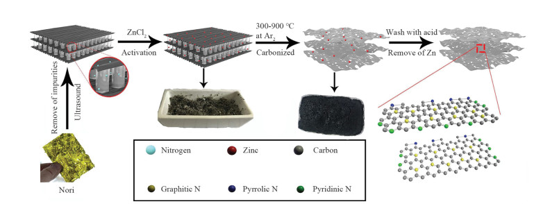
For the purpose of achieving nitrogen self-doped porous carbon, the catalysts were synthesized according to a previous study [47] with a modification of the preparation procedure, as shown in the Scheme 1. First, the nori was treated with deionized water and vacuum dried at 50 ℃ for 11 h. Then the nori was grounded into a powder using a pulverizer and stirred with ZnCl2 concentrated solution (the mass ratio of nori to ZnCl2 was 3:1) for 20 h, then dried in an oven at 80 ℃ for 36 h. After that, the mixture obtained above was heated at an elevated temperature from 300 ℃ to 900 ℃ for 4 h under argon atmosphere. When cooled to 25 ℃, the samples were immersed in 2 mol/L HCl solution for 3 h to eliminate the metal impurities. Further, adopting ultrasonic treatment with 3 mol/L HNO3 for 20 min to strengthen the hydrophilicity of pore carbon surface. After filtration, the catalysts were washed thoroughly with deionized water for a while until neutral, and dried under vacuum at 80 ℃ to obtain target products. The N self-doped porous activated carbons were denoted as N-PAC/T, where T represented the pyrolysis temperature (700, 800, 900 ℃, and so on). For convenient to compare, a contrastive experiment was also put into practice, which was obtained without the activator ZnCl2, denoted as N-C/800.

|
Download:
|
| Scheme 1. Schematic illustration of the synthesis process for N-PAC/T. | |
Scanning electron microscope (SEM) and transmission electron microscope (TEM) images were used to characterize the microstructure and morphology of nori and porous carbon samples (N-PAC/800). SEM reveals that the untreated nori is a three-dimensional multilayered sandwich-like structure, as shown in Fig. S1a (Supporting information). The morphology of N-PAC/800 was confirmed by SEM and TEM. SEM reveals that the N-PAC/800 becomes a sponge-like material after pyrolysis with activator at 800 ℃ (Fig. S2 in Supporting information). The surface of N-PAC/800 is rather rough and the sample possesses a loose, porous structure which is constituted by sheet-like particles. TEM image further confirms that the sample has abundant irregular and porous structure, with an average pore diameter of 22 nm, indicating a high specific surface area (Fig. 1a), the samples synthesized at different pyrolysis temperatures also exhibit similar structures (Fig. S3 in Supporting information), even at low temperatures (300 ℃), a clear pore structure can still be observed. It shows that the activator is the root cause to form pore structure. Not only that, the high-resolution TEM images (Fig. 1b) demonstrate that the N-PAC/800 possesses graphene-like nanosheet structure, which can put down to the multilayered morphology of nori. Moreover, some bright lattice fringes can be observed in the nanosheet structure, and the lattice fringes separated by 0.32 and 0.21 nm, corresponding to the (002) and (100) lattice spacing of hexagonal graphite [50]. TEM results confirm the existence of graphite nanosheets, and indicate that the nori is apt to graphitize by simple pyrolysis.

|
Download:
|
| Fig. 1. (a) TEM (the inset is pore diameter statistics) and (b) high-resolution TEM image and selected area electron diffraction (SAED) pattern (inset) of N-PAC/800. (c) N2 adsorption-desorption isotherms. (d) Raman spectra of N-PAC with different pyrolysis temperature. | |
The crystal structure of the catalysts was investigated by X-ray diffraction (XRD), as Fig. S4 (Supporting information) shows. The two wider diffraction peaks are concentrated around 26.08° and 44.60° respectively, they can be well ascribed to the (002) and (100) lattice face of graphitic carbon, indicating the presence of graphitized structures. It is worth noting that the peak around 26.08° becomes narrower gradually with elevating carbonization temperature, demonstrating that high temperature can effectively improve the degree of graphitization.
The high specific surface area and the porous structure of material not solely can add to the effectual touch area with electrolyte, but provide a large specific area to expose more active sites. Therefore, in order to further survey the characteristics of the pore size and specific surface area, a nitrogen adsorption-desorption test was carried out, as shown in Fig. 1c. All the samples synthesized with activator exhibit type Ⅳ hysteresis loops at a relative pressure (P/P0) > 0.4, and the Ⅳ hysteresis loops become more and more obvious with rising temperature. This finding points to the existence of numerous micro-, meso- and macropores within the material, and with rising temperature, the number of meso-and macropores within carbon material is increased significantly. Surprisingly, the high pyrolysis temperature also can result in increasing the specific surface area of the carbon material. The N-PAC/800 sample exhibits remarkable specific surface area of 1300.58 m2/g by the Brunauer-Emmett-Teller (BET) method. The pore size distribution (Fig. S5a in Supporting information) shows that the shark peaks at around 1.3 nm represent micropores, and wide distribution is assigned to mesopores average pore size from 2.8 nm to 4.5 nm. More detailed data are summarized in Table S1 (Supporting information). As shown in Table S1, high temperature plays an important role during the pyrolysis procedure, which not merely increases the specific surface area of material, but extends the pore volumes. The activator ZnCl2 attacking the biomass carbon material is a chemical reaction process. In the same pyrolysis time (3 h), when the temperature is gradually increased, the reaction rate is accelerated obviously, followed by the specific surface area increasing, which means forming more pore structure [52]. When the pyrolysis temperature is elevated to 900 ℃, the BET specific surface area of N-PAC/900 sample is slightly reduced, which may be due to fracture of the pores at high temperature.
For the purpose of further verifying the N-PAC, Raman spectroscopy was devoted to evaluating defects or structural disturbances (Fig. 1d). The spectrum shows a D-band peak (1364 cm−1) and a G-band peak (1586 cm−1), they represent disordered graphite structure and crystalline graphite carbon respectively. The D-band peak is much wider than the G-band peak, primarily on account of the high degree of disordered graphite structure, which indicates the successful introduction of nitrogen atom leads to the appearance of defects [60]. It can be found that the D-band and G-band intensity are gradually increased with elevating pyrolysis temperature from 300 ℃ to 900 ℃. The results confirm that high temperature is favorable for enhancing the degree of graphitization, which could obviously improve the electrical conductivity of the material, thus enhancing the electrocatalysis performance. The intensity ratio of ID/IG is considered to be an important quantitative measure of graphene structure defects [56]. The ID/IG ratio of samples with different synthetic conditions has been listed, as shown in the inset of Fig. 1d. It is found that compared with the NC/800 sample (without activator), the intensity ratio of other samples increases obviously, indicating that activator brings about the appearance of plentiful mesopores, which can significantly improve the porosity of the material. Moreover, the ID/IG ratio of the samples prepared by activator increase from 0.80 to 0.91 gradually with the pyrolysis temperature elevated from 300 ℃ to 800 ℃, which manifest that rising temperature is beneficial to form defects during the pyrolysis process. The introduction of defects has proven to be a high active site for metal-free nanocarbon [61]. In addition, the redistribution of charge caused by the defect greatly enhances the hydrophilicity of the surface of the material, and the crystal face enhances adsorption capacity for the hydrogen atom in H2O, which is advantageous for further water decomposition [62]. The ID/IG of N-PAC/900 is slightly lower than that of N-PAC/800, the reason is attributed to the excessive pyrolysis temperature which makes the carbon skeleton structure become unstable. N-PAC/800 has the highest mass ratio of N in the comparison system, so it also possesses the most defects. In addition, the ratio shows that the area, the number of defects, and the proportion of N elements are highly consistent with the temperature change trend. The introduction of N element is the main cause to form defects, and the increasing amount of pores allows more N element in the biomass to participate in pyrolysis process. Accordingly, this process can raise the possibility of introducing N element into the biomass carbon skeleton.
XPS tests were put into effect to analyze elemental compositions in porous carbon materials further. The spectra in Fig. S5b (Supporting information) shows that all catalysts contain only C 1s (about 284 eV), O 1s (about 532 eV), and N 1s (about 400 eV) electrons. And even though the N 1s peak is relatively weaker, it can still forcefully attest that the as-prepared samples were exactly N-doped carbon. The respective mass percentages of C, N, and O elements are shown in Table S1. The content of the N element in all porous carbon materials is little change, which means that temperature variation has no influence on the N content. So as to analyze the chemical status of N element, porous activated carbon with different pyrolysis temperatures was further detected by high-resolution XPS scanning, as shown in Fig. S6 (Supporting information). The N 1s peak can be deconvoluted into three nitrogen groups, which are attributed to pyridine-N (398.4 ± 0.3 eV), pyrrole-N (399.8 ± 0.3 eV), graphite-N (400.9 ± 0.3 eV) respectively. Among these chemical statuses of N element, pyridinic N can improve the onset potential and hydrophilicity of porous carbon. Additional, Graphitic-N can prominently heighten the limiting current density. In comparison, graphite N atoms have a lower electronegativity, reducing the electron density of adjacent carbon, which makes the transfer of electrons between carbon atoms and nitrogen atoms easier. This process promotes the dissociation of O2, and helps to form stable chemical bonds. This structure can not only improve the transmission rate of the first electron, but also prefer the way of four-electron reduction, while pyrrolic N has little influence on electrocatalytic activity [63]. In view of the integrated peak area, the ratio of each nitrogen component can be quantified, as Fig. S7 (Supporting information) shows. Graphite-N is in the highest flight species in all catalysts, and the proportion of graphite-N increases substantially with rising temperature. Moreover, compared with N-C/800 sample, the sample prepared with activator possesses a higher percentage of graphite-N, which means the introduction of activator during preparation process not only can enlarge the specific surface area of the catalysts, but also benefit to the increasing percentage of graphite-N. The graphite-N proportion of N-PAC/800 is slightly higher than N-PAC/900, probably on account of the lower stability of graphite-N at a higher temperature. This result is also consistent with the previous assumptions.
The abundance and excellent electrochemical activity of N species in as-prepared porous carbon material make it a competitive candidate as high-efficiency ORR electrocatalysts. Therefore, linear scan voltammetry (LSV) was firstly performed by using a rotating disk electrode (RDE) in an atmosphere of 0.1 mol/L KOH under a saturated O2 atmosphere (Fig. 2a). The ORR polarization curves of N-PAC/T and 20% commercial Pt/C were recorded in the test at a rotational speed of 1600 rpm. It can be seen that a non-zero cathode current of all the samples appears when the electrode is negatively scanned, with an onset potential of 0.92 V for N-PAC/800, which approaches to commercial Pt/C catalyst (0.93 V). The potential is quite closely followed by an onset potential of +0.87 V (N-PAC/700), +0.85 V (N-PAC/900), +0.84 V (N-PAC/500), +0.80 V (N-PAC/300) and +0.74 V (NC/800). In addition, with the increasing of the voltage, the current density of as-prepared porous carbon increases extremely rapidly in a very small voltage range. The half-wave potential (3 mA/cm2) of N-PAC/800 is as high as 0.85 V, which is much higher than those of other samples, even superior to commercial Pt/C (0.81 V). And the limiting current density of N-PAC/800 is 6.34 mA/cm2, which performance is equivalent to commercial Pt/C. On the basis of the above outcome, we can suggest that N-PAC/800 is the greatest electrocatalyst among the family catalysts, and even superior to almost N-doped carbon catalysts reported so far, especially those derived from animal or plant biomass (Table S2 in Supporting information).

|
Download:
|
| Fig. 2. (a) ORR polarization curves of different samples in O2-saturated 0.1 mol/L KOH with a scan rate of 10 mV/s at 1600 rpm. (b) The linear fitting of Δj vs. scan rates in 0.1 mol/L KOH, the inset is number of electron transfer fitted at different potentials. (c) LSV curves of N-PAC/800 at different pH value. (d) Current-time (i–t) responses for ORR at +0.4 V vs. RHE in an O2-saturated 0.1 mol/L KOH solution at N-PAC/800 and Pt/C modified electrode with the addition of 5 mol/L methanol at 2000 s. | |
In order to study the kinetics of ORR in a 0.1 mol/L KOH electrolyte, the Koutecky-Levich (K-L) equation was devoted to identifying the number of electrons concerned in ORR. Firstly, the ORR polarization curve of N-PAC/800 at different speeds was tested by RDE (Fig. S8 in Supporting information). The polarization curves exhibit that the ORR limit current density is increasing gradually with boosting the rotation speed (from 300 rpm to 2800 rpm), while onset potential and the half-wave potential are almost unchanged. The corresponding K-L plots of N-PAC/800 at different potentials were drawn in Fig. 2b. We inspected that the reverse current density manifests a good first-order dependence on the square root of the rotational speed. The above result evidently indicates the first-order reaction kinetics relative to the oxygen concentration and the similar electron transfer number (n) of the ORR at different potentials. As shown in Fig. 2b, the slope of K-L curve is calculated about 3.88 at the potentials from 0.4 V to 0.9 V. This testifies that the porous carbon catalyzes the ORR via ideal four-electron reaction route, which is much like the property of commercial Pt/C catalyzing ORR in a 0.1 mol/L KOH electrolyte.
We believe that rich defects and graphite N ratio of carbon materials are suitable for electron transport and transfer. And increased pyrolysis temperature can heighten the degree of graphitization and enhance the content of graphite N, followed by significantly improving the conductivity of porous carbon materials. Therefore, the electrochemical impedance spectroscopy (EIS) measurement was performed at the range from 1 Hz to 10 kHz in a 1 mol/L KOH system to further study the resistance and ion transport action of our catalysts. The characteristics of the EIS are analyzed by further fitting the Nyquist resistance diagram; Rct represents equivalent resistance in the inset image in Fig. S9 (Supporting information). The Nyquist diagram shows a high-frequency semicircle, its diameter represents the charge transfer resistance between the electrode and the electrolyte in electrochemistry. It also can reflect the resistance of materials to some extent, which is caused by electrolyte ions diffusing into the porous structure of the catalysts. It can be observed that Pt/C displays a quite low impedance value of 121.5 Ω due to its excellent precious metal properties. The impedances of N-PAC/800, N-PAC/700, and N-PAC/900 are 169.3 Ω, 208.4 Ω and 234.7 Ω, respectively, indicating a higher charge transfer resistance compared with commercial Pt/C. It is well known that graphene is composed of sp2 carbon. Carbon atoms are stacked tightly to form the unique hexagonal lattice, with excellent electrical conductivity. And when a heteroatom (such as N) replaces a certain carbon atom, defect regions will appear by covalent bonding of graphene due to the sp2 network is destroyed [63]. And the same is true for porous carbon materials. The N-PAC/800 owns the larger specific surface area and the richer defects than other samples, which make it have more excellent mass transfer and electron transfer rate. The impedance value of N-PAC/500, N-PAC/300 and NC/800 are 640.32 Ω, 879.4 Ω and 1140.3 Ω, respectively, which are corresponding to their relatively low specific surface area and defects compared to N-PAC/800. According to EIS data, the relatively low oxygen reduction performances of N-PAC/300 and N-PAC/500 are probably attributed to sluggish charge transfer.
Note that as-prepared N-PAC/800 catalyst has shown the higher properties than the catalysts prepared at other temperatures. To further accurately evaluate the ORR catalytic characteristic of N-PAC/800, a cyclic voltammetry (CV) measurement was accomplished in O2 versus N2-saturated 0.1 mol/L KOH solution at the scan rate of 10 mV/s (Fig. S10 in Supporting information). It can be observed that the profiles of the two curves are similar, while a prominent peak of cathodic oxygen reduction occurs at −0.246 V in the saturated O2 electrolyte, this confirms that N-PAC/800 occurs the ORR on the surface of the electrode. Other samples prepared at different temperatures are also tested by CV measurement to eliminate individual accidental errors (Fig. S11 in Supporting information). And all the catalysts show self-evident cathodic peaks. The reduction peak position of the as-prepared samples were −0.278 V (N-PAC/300), −0.243 V (N-PAC/500), −0.258 V (N-PAC/700), and −0.232 V (N-PAC/900), which are close to commercial Pt/C (−0.213 V), indicating that the catalytic path of the porous carbon materials are similar with the four-electron catalytic path of Pt/C. The subtle difference of the reduction peak position may be since the catalytic mechanism of prepared catalysts include another catalytic pathway (but dominated by a four-electron path), so that a single selectivity of the catalytic pathway is weaker than Pt/C. It can also be seen from the CV curve that the significant difference between the samples is the peak intensity; this is consistent with the LSV activity evaluation in Fig. 2a, reflecting the catalytic efficiency of each catalysts.
It is most certainly true that the ORR or battery field needs to cope with various harsh environments in the future applications. And the tolerance to pH changes of materials is an important indicator for catalysts. Therefore, we evaluated the ORR catalytic activity of N-PAC/800 by LSV tests across a pH range from 1 to 14 (Fig. 2c). The polarization curves reveal that the most significant drop of half-wave potential is 54 mV and the limit current is 0.42 mA/cm2 respectively, with pH value decreasing from 14 to 1. The onset potential occurs only a tiny change under the entire pH value, indicating as-prepared porous activation carbon catalysts possess a high tolerance to pH changes and is suitable for catalysis across the entire pH range.
In order to apply fuel cells as an efficacious ORR catalyst, the catalyst should have both outstanding long-term stability and high catalytic selectivity for fuel oxidation [64]. Therefore, we further assessed the methanol-resistant and stability of N-PAC/800 and commercial Pt/C using chronoamperometric measurements at a moderate potential (+0.4 V) and the rotation speed of 1600 rpm. As Fig. 2d shows, when 5 mol/L methanol was squirted into an electrolyte in 2000 s, the ORR current of commercial Pt/C dropped down sharply to 40%. On the contrary, N-PAC/800 did not show an obvious decreased in the current. Besides, the ORR performance of N-PAC/800 can still maintain 90% activity after continuous operation for 4000 s, which is significantly better than the Pt/C catalyst under the same condition. This indicates that the catalyst has extraordinary selectivity for oxygen and can avoid the cross-effect of methanol. We also performed an accelerated durability test (ADT) to evaluate the durability of the catalyst further. The CV curves are recorded 5000 cycles so as to contrast the half-wave potential and ORR activities during potential cycling. As shown in Fig. S12 (Supporting information), after 5000 cycles of CV test, the half-wave potential decreases only 19 mV, which is almost negligible for the ORR. The high-resolution TEM and XPS are performed to verify the N-PAC/800 after 5000 CV cycles. It is found that three kinds of N-species in the carbon skeleton and the porous morphology of the catalyst do not change, indicating the excellent structural stability of electrocatalyst (Fig. S13 in Supporting information). After a comprehensive consideration of these verified results, we can claim that such porous activation carbon with prominent ORR electrocatalytic activity, strong receivable ability of pH changes, extraordinary selectivity and superior long-term stability, hold great promise as an ORR electrocatalyst.
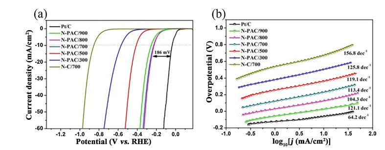
To further understand the potential of our as-prepared catalysts as bifunctional catalysts, the porous carbon materials were tested for HER performance by LSV evaluation. As shown in Fig. 3a, the HER performance of NC/800 is very poor, and the potential corresponding to the onset current is 855 mV. As for the porous carbon samples, it can be found that the performance of all the samples exhibits more significant improvement than N-C/800. In addition, the HER onset potential of porous carbon is gradually reduced from 573 mV to 218 mV with increasing the pyrolysis temperature from 300 ℃ to 800 ℃. It is gratifying that the HER onset potential of N-PAC/800 is just less than 186 mV of 20 wt% Pt/C catalyst, which manifest that N-PAC/800 possesses high HER activity as metal-free carbon-based catalysts. When the pyrolysis temperature is further raised to 900 ℃, the onset potential of N-PAC/900 is 257 mV, which is slightly less 40 mV than N-PAC/800. This could be assigned to the reduction of specific surface area and graphite-N proportion of N-PAC/900 compared to N-PAC/800. In order to obtain the change of current density per unit voltage, the Tafel fitting of the LSV curves of each sample is shown in Fig. 3b. The Tafel slope of NC/800, N-PAC/300, N-PAC/500, N-PAC/700, N-PAC/800, N-PAC/900, are 156.8, 125.8, 119.1, 113.4, 104.3 and 121.1 dec−1, respectively. This result suggests that the reaction may be involving a Volmer-Heyrovsky reaction mechanism.

|
Download:
|
| Fig. 3. (a) LSV curves of NC/800, N-PAC/300, N-PAC/500, N-PAC/700, N-PAC/800 and Pt/C in 0.5 mol/L H2SO4 for HER and corresponding Tafel slopes (b). | |
The stability of porous carbon material is a critical factor that cannot be ignored in ensuring porous carbon materials utilized for practical applications. The durability test of N-PAC/800 was carried out. As shown in Fig. S14 (Supporting information), there is only a tiny attenuation of onset potential after 5000 cycles of CV circulation, and the catalyst can still maintain 80% activity after the 30, 000 s of continuous voltage. This result confirms that as-prepared porous carbon is effective as a long-term electrocatalyst. Similar to the preceding ORR test for the tolerance to pH changes of the catalyst, the LSV tests were performed under different pH value (Fig. S15 in Supporting information). It can be found that the onset of the potential changes slightly when the pH value of electrolyte increase from 1 to 14. In order to compare the change of the onset potential at different pH, the onset of the potential change is amplified as shown in the inset of Fig. S15 (Supporting information). The onset potential undulates slightly (∼71 mV) during the pH value increasing from 1 to 14, revealing that the catalyst has a quite high tolerance to pH changes and excellent chemical stability.
Based on the above research and analysis, the N-PAC/800 as electrocatalyst shows outstanding electrocatalytic performances on both ORR and HER, which could be ascribed to the following principal reasons. Firstly, the porosity of materials plays a decisive role in the improvement of electrocatalytic activity. Large mesopore volume and high specific surface area provide enough active sites of porous carbon with better exposure, which endow porous carbon with excellent electrocatalytic performance. Secondly, the introduction of N species leads to a higher positive charge density on adjacent C atoms, and it is easier to adsorb free O2 molecules or act as electron acceptors than other unintroduced sites, increasing the adsorption capacity of H* to enhance H2 release capacity. Finally, the three-dimensional multilayered structure is more conducive to mass transfer and diffusion of the reactants, abundant defects can better accelerate electron transport.
In summary, we successfully exploited an easy-operate, cheap production preparation strategy based on pyrolysis at controllable temperatures for the manufacture of novel N-PAC materials with large specific surface area (1300.58 m2/g). As-prepared porous carbon materials show outstanding electrocatalytic activity due to its developed porosity, high graphite-N ratio, and abundant defects, resulting in accelerating electron and reactant transport. As the best activity of the sample, N-PAC/800 exhibit not only excellent ORR catalytic activity (ΔE1/2 = 0.85 V) even higher than commercial Pt/C (ΔE1/2 = 0.81 V), but also satisfactory HER performance (Eonset = 0.218 V). Besides, as-prepared electrocatalyst also possesses prominent additional important properties, such as enhanced methanol tolerance, high long-term and chemical stability. These brilliant properties indicate the great potential of such bifunctional electrocatalyst for applications to energy conversion and reserve.
Declaration of competing interestThe authors report no declarations of interest.
AcknowledgmentsThis work was supported by the National Natural Science Foundation of China (Nos. 21673290, U1662103), Science Foundation of China University of Petroleum, Beijing (No. 2462017YJRC027), the Strategic Cooperation Technology Projects of CNPC and CUPB (No. ZLZX2020-04).
Appendix A. Supplementary dataSupplementary material related to this article can be found, in the online version, at doi:https://doi.org/10.1016/j.cclet.2020.09.027.
| [1] |
M. Armand, J.M. Tarascon, Nature 451 (2008) 652-657. DOI:10.1038/451652a |
| [2] |
M. Shao, Q. Chang, J.P. Dodelet, R. Chenitz, Chem. Rev. 116 (2016) 3594-3657. DOI:10.1021/acs.chemrev.5b00462 |
| [3] |
M. Zhou, H.L. Wang, S. Guo, Chem. Soc. Rev. 45 (2016) 1273-1307. DOI:10.1039/C5CS00414D |
| [4] |
M. Carmo, D.L. Fritz, J. Mergel, D. Stolten, Int. J. Hydrogen Energy 38 (2013) 4901-4934. DOI:10.1016/j.ijhydene.2013.01.151 |
| [5] |
W. Meng, X. Bai, B. Wang, et al., Energy Environ. Mater. 2 (2019) 172-192. DOI:10.1002/eem2.12038 |
| [6] |
Y. Zhao, K. Kamiya, K. Hashimoto, S. Nakanishi, J. Phys. Chem. C 119 (2015) 2583-2588. DOI:10.1021/jp511515q |
| [7] |
N. Garg, M. Mishra, Govind, A.K. Ganguli, RSC Adv. 5 (2015) 84988-84998. DOI:10.1039/C5RA16937B |
| [8] |
J. Ahmed, Y. Mao, Electrochim. Acta 212 (2016) 686-693. DOI:10.1016/j.electacta.2016.06.122 |
| [9] |
Y. Yang, H. Fei, G. Ruan, J.M. Tour, Adv. Mater. 27 (2015) 3175-3180. DOI:10.1002/adma.201500894 |
| [10] |
B.C.H. Steele, A. Heinzel, Nature 414 (2001) 345-352. DOI:10.1038/35104620 |
| [11] |
R. Bashyam, P. Zelenay, Nature 443 (2006) 63-66. DOI:10.1038/nature05118 |
| [12] |
F. Cheng, J. Chen, Chem. Soc. Rev. 41 (2012) 2172-2192. DOI:10.1039/c1cs15228a |
| [13] |
H.A. Gasteiger, S.S. Kocha, B. Sompalli, F.T. Wagner, Appl. Catal. B 56 (2005) 9-35. DOI:10.1016/j.apcatb.2004.06.021 |
| [14] |
J. Suntivich, H.A. Gasteiger, N. Yabuuchi, et al., Nat. Chem. 3 (2011) 546-550. DOI:10.1038/nchem.1069 |
| [15] |
H. Khani, N.S. Grundish, D.O. Wipf, J.B. Goodenough, Adv. Energy Mater. 10 (2019) 1903215. |
| [16] |
G.R. Xu, J. Bai, L. Yao, et al., ACS Catal. 7 (2016) 452-458. |
| [17] |
S. Li, K. Bi, L. Xiao, X. Shi, Nanotechnology 28 (2017) 495601. DOI:10.1088/1361-6528/aa91c4 |
| [18] |
D. Liu, C. Wu, S. Chen, et al., Nano Res. 11 (2018) 2217-2228. DOI:10.1007/s12274-017-1840-8 |
| [19] |
Y. Liu, G. Han, X. Zhang, et al., Nano Res. 10 (2017) 3035-3048. DOI:10.1007/s12274-017-1519-1 |
| [20] |
H. Yin, S. Zhao, K. Zhao, et al., Nat. Commun. 6 (2015) 6430. DOI:10.1038/ncomms7430 |
| [21] |
X. Huang, Z. Zhao, L. Cao, et al., Science 348 (2015) 1230-1234. DOI:10.1126/science.aaa8765 |
| [22] |
M.D. Radin, D.J. Siegel, Energy Environ. Sci. 6 (2013) 2370-2379. DOI:10.1039/c3ee41632a |
| [23] |
J. Zhu, M. Xiao, Y. Zhang, et al., ACS Catal. 6 (2016) 6335-6342. DOI:10.1021/acscatal.6b01503 |
| [24] |
G. Li, X. Wang, J. Fu, et al., Angew. Chem. Int. Ed. 55 (2016) 4977-4982. DOI:10.1002/anie.201600750 |
| [25] |
J.W.D. Ng, M. Tang, T.F. Jaramillo, Energy Environ. Sci. 7 (2014) 2017-2024. DOI:10.1039/c3ee44059a |
| [26] |
L. Li, S.H. Chai, S. Dai, A. Manthiram, Energy Environ. Sci. 7 (2014) 2630-2636. DOI:10.1039/C4EE00814F |
| [27] |
J. Wu, H. Yang, Acc. Chem. Res. 46 (2013) 1848-1857. DOI:10.1021/ar300359w |
| [28] |
W. Li, Y. Liu, M. Wu, et al., Adv. Mater. 30 (2018) 1800676. DOI:10.1002/adma.201800676 |
| [29] |
L. Lai, J.R. Potts, D. Zhan, et al., Energy Environ. Sci. 5 (2012) 7936-7942. DOI:10.1039/c2ee21802j |
| [30] |
D. Yan, S. Dou, L. Tao, et al., J. Mater. Chem. A 4 (2016) 13726-13730. DOI:10.1039/C6TA05863A |
| [31] |
Y. Li, H. Zhang, Y. Wang, et al., Energy Environ. Sci. 7 (2014) 3720-3726. DOI:10.1039/C4EE01779J |
| [32] |
H. Tabassum, W. Guo, W. Meng, et al., Adv. Energy Mater. 7 (2017) 1601671. DOI:10.1002/aenm.201601671 |
| [33] |
Y. Nie, L. Li, Z. Wei, Chem. Soc. Rev. 44 (2015) 2168-2201. DOI:10.1039/C4CS00484A |
| [34] |
Y. Xu, M. Kraft, R. Xu, Chem. Soc. Rev. 45 (2016) 3039-3052. DOI:10.1039/C5CS00729A |
| [35] |
B. Wang, L. Xu, G. Liu, et al., J. Mater. Chem. A 5 (2017) 20170-20179. DOI:10.1039/C7TA05002J |
| [36] |
B.B. Huang, Z.Y. Luo, J.J. Zhang, Z. Xie, RSC Adv. 7 (2017) 17941-17949. DOI:10.1039/C6RA28381K |
| [37] |
Z. Pei, H. Li, Y. Huang, et al., Energy Environ. Sci. 10 (2017) 742-749. DOI:10.1039/C6EE03265F |
| [38] |
Y. Liu, B. Huang, X. Lin, Z. Xie, J. Mater. Chem. A 5 (2017) 13009-13018. DOI:10.1039/C7TA03639F |
| [39] |
C. Han, J. Wang, Y. Gong, et al., J. Mater. Chem. A 2 (2014) 605-609. DOI:10.1039/C3TA13757K |
| [40] |
Z. Zhang, G.M. Veith, G.M. Brown, et al., J. Chem. Commun. 50 (2014) 1469-1471. DOI:10.1039/C3CC48942F |
| [41] |
L. Yang, J. Shui, L. Du, et al., J. Adv. Mater. 31 (2019) 1804799. DOI:10.1002/adma.201804799 |
| [42] |
B. Huang, Y. Liu, Z. Xie, J. Mater. Chem. A 5 (2017) 23481-23488. DOI:10.1039/C7TA08052B |
| [43] |
M.M. Titirici, R.J. White, N. Brun, et al., Chem. Soc. Rev. 44 (2015) 250-290. DOI:10.1039/C4CS00232F |
| [44] |
N. Brun, P. Osiceanu, M.M. Titirici, J. ChemSusChem 7 (2014) 397-401. DOI:10.1002/cssc.201301165 |
| [45] |
Z. Yang, H. Zhang, J. Petrol. Sci. 5 (2008) 183-188. DOI:10.1007/s12182-008-0029-x |
| [46] |
J.H. Yuan, S. Zhou, T.D. Peng, J. Petrol. Sci. 15 (2018) 644-656. DOI:10.1007/s12182-018-0237-y |
| [47] |
X. Liu, Y. Zhou, W. Zhou, L. Li, S. Huang, S. Chen, Nanoscale 7 (2015) 6136-6142. DOI:10.1039/C5NR00013K |
| [48] |
H. Huang, X. Wei, S. Gao, Electrochim. Acta 220 (2016) 427-435. DOI:10.1016/j.electacta.2016.10.108 |
| [49] |
J. Zhang, S. Wu, X. Chen, M. Pan, S. Mu, J. Power Sources 271 (2014) 522-529. DOI:10.1016/j.jpowsour.2014.08.038 |
| [50] |
W. Huang, H. Zhang, Y. Huang, W. Wang, S. Wei, Carbon 49 (2011) 838-843. DOI:10.1016/j.carbon.2010.10.025 |
| [51] |
J. Zhang, S. Wu, X. Chen, et al., RSC Adv. 4 (2014) 32811-32816. DOI:10.1039/C4RA06495J |
| [52] |
C.J. Chen, L.B. Wei, P.C. Zhao, et al., Adv. Mater. Res. 152-153 (2011) 1322-1327. |
| [53] |
F. Pan, Z. Cao, Q. Zhao, H. Liang, J. Zhang, J. Power Sources 272 (2014) 8-15. DOI:10.1016/j.jpowsour.2014.07.180 |
| [54] |
K.N. Chaudhari, M.Y. Song, J.S. Yu, Small 10 (2014) 2625-2636. DOI:10.1002/smll.201303831 |
| [55] |
M. Li, Y. Xiong, X. Liu, et al., J. Mater. Chem. A 3 (2015) 9658-9667. DOI:10.1039/C5TA00958H |
| [56] |
S. Gao, H. Fan, S. Zhang, J. Mater. Chem. A 2 (2014) 18263-18270. DOI:10.1039/C4TA03558E |
| [57] |
G. Han, M. Hu, Y. Liu, et al., J. Solid State Chem. 274 (2019) 207-214. DOI:10.1016/j.jssc.2019.03.027 |
| [58] |
J. Fleurence, Trends Food Sci. Technol. 10 (1999) 25-28. DOI:10.1016/S0924-2244(99)00015-1 |
| [59] |
H. Nöda, J. Appl. Phycol. 5 (1993) 255-258. DOI:10.1007/BF00004027 |
| [60] |
S. Mu, H. Tang, S. Qian, M. Pan, R.Z. Yuan, Carbon 44 (2006) 762-767. DOI:10.1016/j.carbon.2005.09.010 |
| [61] |
Y. Jia, L. Zhang, A. Du, et al., Adv. Mater. 28 (2016) 9532-9538. DOI:10.1002/adma.201602912 |
| [62] |
S. Gao, Y. Chen, H. Fan, et al., J. Mater. Chem. A 2 (2014) 3317-3324. DOI:10.1039/c3ta14281g |
| [63] |
L. Lai, J.R. Potts, D. Zhan, et al., Energy Environ. Sci. 5 (2012) 7936-7942. DOI:10.1039/c2ee21802j |
| [64] |
J. Duan, S. Chen, M. Jaroniec, S.Z. Qiao, ACS Catal. 5 (2015) 5207-5234. DOI:10.1021/acscatal.5b00991 |