 2021, Vol. 32


b Hubei Engineering Research Center of RF-Microwave Technology and Application, Wuhan University of Technology, Wuhan 430070, China
As a type of one-dimensional nanomaterials, carbon nanotubes (CNTs) have been favored by researchers because of their unique structure and outstanding performancein conduction, mechanics and energy conversion [1-4]. Physical and chemical methods, including arc discharge method, wet chemistry method, chemical vapor deposition (CVD) method and concurrent thermal decomposition method, have been proposed and greatly developed to access CNTs [3-8]. However, the reported methods for preparation of CNTs stillface limited scale, high energy consumption and expensive equipment [9]. Similarly, these challenges are existed for preparation of nitrogen-doped CNTs (N-CNTs). As reported, the doping of N atoms can effectively modify the electronic structure and carbon defects of the CNTs, resulting in an enhanced catalytic performance in oxygen reduction reaction (ORR), hydrogen evolution reaction (HER), oxygen evolution reaction (OER), lithium-ion batteries (LIB) and lithiumsulfur (Li-S) batteries [10-17]. For example, Dai et al. reported that the rationally designed N-CNTs as the ORR catalysts exhibited remarkably performance with a half-wave potential (E1/2) of 0.81 V (vs. reversible hydrogen electrode, RHE) [18]. Also, Wei et al. reported a modified thermal CVD method with two heating zones and different nitrogen precursors to grow aligned N-CNTs, which showed an outstanding ORR catalytic performance with an onset potential (E0) of 0.88 V (vs. RHE) [19]. However, the ORR performance for N-CNTs synthesized by these methods is still far from commercial Pt/C and failure to meet the practical requirements.
To further improve the catalytic performance of N-CNTs, metal loading/doping has been achieved on N-CNTs [3, 20]. For instance, Yin et al. successfully loaded high-dispersed Pt nanoparticles (NPs) on the surface of intact graphitic CNTs via electrostatic self-assembly. The obtained material possessed a high ORR activity with half-wave potential (E1/2) of 0.82 V (vs. RHE) and excellent stability in oxygen-saturated 0.5 mol/L H2SO4 solution [21]. Feng et al. prepared Co/CoNx/N-CNT/C electrocatalyst via heating treatment of Co-mela-BDC under nitrogen atmosphere, which also exhibited a good ORR performance (E1/2 = 0.80 V, vs. RHE) [22]. Similar methods by using mixtures of polymers, metal salts or commercial nanotubes to get Co and N co-doped nanotubes in following nitrogen/argon gas have been reported by Mu et al. and Cheng et al. [23-25]. These studies provide insight information for improving the activity of CNT-based catalysts.
Herein, we propose a facile and cost-effective method to access cobalt and N co-doped CNTs (Co/N-CNTs), by using cobalt zeolitic imidazolate framework (ZIF-67) as the single precursor and annealing at high temperature in a negative pressure environment. Compared with conventional methods by annealing in following gas (Table S1 in Supporting information), our method can greatly save gas (such as nitrogen/argon) and reduce cost. Also, the prepared Co/N-CNTs exhibit outstanding oxygen reduction catalytic activity, stability and the fuel crossover tolerance, due to the highly content of pyridinic nitrogen and degree of graphitization, thus providing a big potential for application in fuel cells.
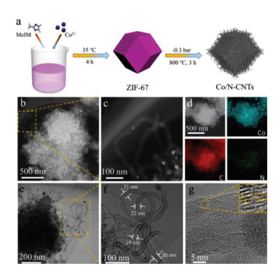
The synthetic process of Co/N-CNTs is shown in Fig. 1a. The precursor ZIF-67 was first synthesized by using cobalt ions as metallic, 2-methylimidazole as the organic liner and methanol as the solution. Transmission electron microscopy (TEM) images in Fig. S1 (Supporting information) reveal that the obtained ZIF-67 nanocrystals possess a standard dodecahedron shape with an average diameter of 750 nm [26]. After carbonization at 800 ℃ under flowing N2 gas, the nitrogen-doped carbon coated Co nanoparticles (Co NPs/NC) with collapse on the face of polyhedral framework were obtained (Fig. S2a in Supporting information). Also, the highly aggregated Co nanoparticles were generated (Fig. S3 in Supporting information). In contrast, after carbonization ZIF-67 at 800 ℃ for 3 h in a negative pressure environment, abundant Co and N co-doped CNTs were emerged from the polyhedral framework (Fig. 1a), as demonstrated by TEM, scanning electron microscope (SEM) and high-angle annular dark-field scanning transmission electron microscope (HAADF-STEM) measurements (Fig. 1, Figs. S2 and S4 in Supporting information). Highresolution TEM (HRTEM) image in Fig. 1f further reveals that the average diameter of the CNTs is about 20 nm and the Co nanoparticle at the tip of CNTs is encapsulated by few-layer graphitic carbon, proving that the generation of CNTs obeys the tip growth mode [27]. Also, it can be clearly concluded from the TEM images that the average diameter of Co nanoparticles in Co/N-CNTs (16.95 nm) is much smaller than that of Co NPs/NC (37.13 nm) (Figs. 1b and e, Figs. S3-S5 in Supporting information), suggesting the negative pressure can prohibit the aggregation of Co NPs efficiently. As reported in the literature, these smaller Co nanocrystals can catalyze the rearragement of carbon atoms, resulting the formation of CNTs [9, 28]. The CNTs have high crystallinity and visible graphitic carbon layers with interplanar distance of ~0.35 nm, corresponding to the C (002) (Fig. 1g) [29]. A low resolution of energy dispersive spectrometer (EDS) element mapping images (Fig. 1d) reveal that Co, C, N are uniformly dispersed over a whole ZIF-67-derived framework. Moreover, Co/N-CNTs obtained at different temperatures and different carbonization time were studied (Figs. S6 and S7 in Supporting information).

|
Download:
|
| Fig. 1. (a) Schematic synthesis process, (b, c) HAADF-STEM images, (d) EDS mappings, (e, f) TEM images and (g) HRTEM image of Co/N-CNTs. | |
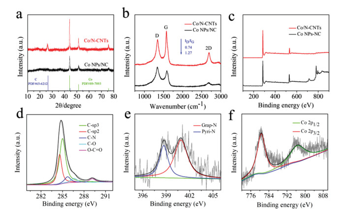
X-ray diffraction (XRD) and Raman were performed to further compare the structure of the obtained Co/N-CNTs and Co NPs/NC. One of the peaks located at 26.5° corresponds to C (Graphite, PDF No. 65-6212), and the remaining three peaks at about 44.3°, 51.5° and 75.9° can be indexed to Co (cobalt, PDF No. 89-7093) (Fig. 2a). In contrast, Co NPs/NC have no obvious peak of graphite carbon at about 26.5°, indicating that pyrolysis in negative pressure can promote the carbon graphitization. Also, the N2 adsorption-desorption isotherms and pore size distributions of Co/N-CNTs and Co NPs/NC were tested and analyzed (Fig. S8 in Supporting information). The specific surface area of Co/N-CNTs is 246.4 m2/g, which is comparable to that of Co NPs/NC (268.0 m2/g). The Co/N-CNTs exhibit a typical type Ⅳ adsorption isotherm and a steeper hysteresis line, indicating that Co/N-CNTs have abundant mesopores [30]. This can be further obtained from the pore size distribution images. In Figs. S6c and S6d, the pore size distribution images reveal Co NPs/NC possess a lot of micropores, while Co/N-CNTs have abundant mesopores (mainly concentrated at around 7 nm), which is close to the inner diameter of CNTs. Raman characteristic signatures for both Co/N-CNTs and Co NPs/NC exhibit three band features at about 1350 cm-1, 1580 cm-1 and 2700 cm-1, namely the D band, G band and 2D band (Fig. 2b) [31]. The D band corresponds disordered sp3 carbon or defected carbon, and G band corresponds graphite sp2 carbon [32, 33]. The ID/IG ratio drastically reduced by the assist of negative pressure from 1.27 to 0.74, suggesting that the higher degree of graphitization of Co/N-CNTs than Co NPs/NC. Additionally, Co/N-CNTs have a remarkable 2D peak in comparison with Co NPs/NC. The 2D peak, as a salient feature of graphene, proves the presence of graphene/graphited layers in Co/N-CNTs [34].

|
Download:
|
| Fig. 2. (a) XRD pattern, (b) Raman spectra, (c) XPS spectra of Co/N-CNTs and Co NPs/NC. High- resolution XPS spectra of (d) C 1s, (e) N 1s and (f) Co 2p of Co/N-CNTs. | |
The X-ray photoelectron spectroscopy (XPS) was used to further characterize the chemical composition on the surface of the obtained materials. The atomic ratio of Co for Co/N-CNTs is 0.63%, which is much lower than that of Co NPs/NC (5.61%) (Fig. 2c and Table S2 in Supporting information). The low Co content the surface of Co/N-CNTs is possibility due to the Co nanoparticles are encapsulated by graphitic carbon layers, as revealed in HRTEM image (Fig. 1f). This can be further demonstrated by the much high content of Co (39.84 wt%) detected by inductively coupled plasmaoptical emission spectra (ICP). For the high-resolution C 1s spectra, there are two peaks at ~284.5 eV and ~285 eV corresponding to C-sp2 and C-sp3, respectively (Fig. 2d and Fig. S9a in Supporting information) [34]. The high-resolution N 1s XPS spectrum suggests the N type of Co/N-CNTs can be assigned to pyridinic N (pyri-N, ~398.7 eV) and graphitic N (grap-N, ~401.8 eV) (Fig. 2e and Fig. S9b in Supporting information) [20, 35]. It was reported that pyri-N can create active sites for ORR, contributing an enhanced ORR performance [36-39]. As shown in Fig. S10 (Supporting information), Co/N-CNTs possess a higher content of pyri-N (35.5%) than that of Co NPs/NC (28.7%), indicating the former may have a better ORR activity. The high-resolution Co 2p spectrum can be further deconvolved into two subpeaks of at 779.4 eV and 793.5 eV, corresponding to the Co 2p3/2 and Co 2p1/2 levels (Fig. 2f).
The ORR performance of the as-prepared Co/N-CNTs was evaluated in an alkaline environment of 0.1 mol/L KOH. As shown in Fig. 3a, the cyclic voltammetry (CV) curve of Co/N-CNTs has a well-defined oxygen reduction absorption peak at 0.785 V (vs. RHE) in an O2-saturated KOH solution, exhibiting that Co/N-CNTs have an obvious ORR activity. Linear sweep voltammetry (LSV) curves reveal that the onset potential (E0) of the obtained Co/N-CNTs (0.975 V) is comparable to that of commercial Pt/C (0.981 V). The half-wave potential (E1/2) of Co/N-CNTs can up to 0.85 V, which is positive than those of commercial Pt/C (0.84 V) and Co NPs/NC (0.80 V) (Fig. 3b), illustrating that Co/N-CNTs have the best ORR activity in alkaline electrolyte. Also, such an ORR performance of Co/N-CNTs is comparable to those reported previously (Table S1). Furthermore, Co/N-CNTs have a lowest Tafel slope (Co/N-CNTs (81 mV/dec) < Pt/C (87 mV/dec) < Co NPs/NC (97 mV/dec)), suggesting that Co/N-CNTs have a similar reaction kinetics process with commercial Pt/C (Fig. 3c). In order to further understand the catalytic reaction mechanism, the Koutechy-Levich (K–L) equation is utilized to study the electrons transferred number in the reaction process. Specifically, we obtained a series of LSV curves from 400 rpm to 2500 rpm by adjusting the rotational rate of the rotating disk electrode in an O2-saturated KOH solution (Fig. 3d). Then, the resulted LSV curves, combined with the K–L equation, were organized into a K–L diagram (the inset of Fig. 3d)[40]. It can be calculated that the electron transfer number of Co/N-CNTs is 3.9, suggesting Co/N-CNTs mainly obey a fourelectron reaction mechanism in ORR process. Also, the ORR activity of Co/N-CNTs prepared at different carbonization temperatures and carbonization time were investigated (Figs. S11 and S12 in Supporting information).

|
Download:
|
| Fig. 3. (a) CV curves recorded in N2-and O2-saturated 0.1 mol/L KOH solution. (b) LSV curves and (c) Tafel slopes of Co/N-CNTs, Co NPs/NC and Pt/C. (d) LSV curves of Co/N-CNTs at different rotation speeds and corresponding K-L plots (inset). (e) Chronoamperometric response at 0.6 V. (f) Chronoamperometric response at 0.6 V after the introduction of methanol. | |
In addition, catalytic stability and the fuel crossover effect were tested for which are important judgments for evaluating catalysts. The chronoamperometry responses were performed at 0.6 V (vs. RHE) under a rotation of 1600 rpm and an O2-saturated 0.1 mol/L KOH electrolyte. As shown in Fig. 3e, after 30, 000 s testing, the current density of Co/N-CNTs retains 98% of the initial current density, which is much higher than that of Pt/C (78%) in the same condition. Besides, only 4 mV decay in half-wave potentials before and after the 30,000 s test and appearance without changing further indicate that Co/N-CNTs have good stability (Figs. S13 and S14 in Supporting information). Meanwhile, it can be observed from Fig. 3f that after 250 s of injecting CH3OH, the current density of Co/N-CNTs is only decreased by 2%, which is significantly better than that of Pt/C (25%), demonstrating that Co/N-CNTs can effectively resist methanol poisoning.
Furthermore, the ORR performance of Co/N-CNTs in acidic environments was estimated. The CV curve of Co/N-CNTs has a clear peak at 0.67 V, indicating that Co/N-CNTs have significant ORR activity (Fig. S15a in Supporting information). The half-wave potential (E1/2) of Co/N-CNTs is 0.715 V, which is only 25 mV lower than that of commercial Pt/C (0.74 V) (Fig. S15b in Supporting information). The electron transfer number is calculated to be 3.94 in accordance with the good fitting of K–L plots, showing that the process is carried out with a 4-electron reaction (Fig. S15e in Supporting information). Moreover, in the stability test, the normalized current of Co/N-CNTs only drops 3% after 30, 000 s testing, while the normalized current of Pt/C drops 26% after 10, 000 s testing, showing that Co/N-CNTs also have better stability than Pt/C in acidic medium (Fig. S15f in Supporting information). More detail can be seen in Supporting information.
In summary, we have successfully developed a facile and cost-effective method to prepare Co/N co-doped CNTs under the effect of negative pressure by using ZIF-67 crystals as precursors. The introduction of negative pressure can effectively prohibit the agglomeration of Co nanoparticles, and facilitate the rearragement of carbon atoms and growth of CNTs. Also, preparation under such negative pressure can greatly save gas and cost. Moreover, the prepared Co/N-CNTs exhibited excellent ORR catalytic activity, stability and the fuel crossover effect tolerance both in alkaline and acidic environment. This synthetic strategy opens a window for preparation of metal/N co-doped CNTs and catalysts for energy conversion.
Declaration of competing interestThe authors declare that they have no known competing financial interests or personal relationships that could have appeared to influence the work reported in this paper.
AcknowledgmentsThis work was financially sponsored by the National Natural Science Foundation of China (Nos. 51701146, 51672204), the Fundamental Research Funds for the Central Universities (No. WUT: 2017IB015), Foundation of National Key Laboratory on Electromagnetic Environment Effects (No. 614220504030617), the National Natural Science Foundation of China (No. 51672204) and the National Key Research and Development Program of China (No. 2016YFA0202603).
Appendix A. Supplementary dataSupplementary material related to this article can be found, in the online version, at doi:https://doi.org/10.1016/j.cclet.2020.04.002.
| [1] |
M.F.L. De Volder, S.H. Tawfick, R.H. Baughman, A.J. Hart, Science 339 (2013) 535-539. DOI:10.1126/science.1222453 |
| [2] |
M. Zhou, H.L. Wang, S. Guo, Chem. Soc. Rev. 45 (2016) 1273-1307. DOI:10.1039/C5CS00414D |
| [3] |
H. Tabassum, A. Mahmood, B. Zhu, et al., Energy Environ. Sci. 12 (2019) 2924-2956. DOI:10.1039/C9EE00315K |
| [4] |
X. Zhu, Y. Zhu, C. Tian, et al., J. Mater. Chem. A 5 (2017) 4507-4512. DOI:10.1039/C6TA09604B |
| [5] |
H.W. Zhu, C.L. Xu, D.H. Wu, et al., Science 296 (2002) 884-886. DOI:10.1126/science.1066996 |
| [6] |
K. Takekoshi, T. Kizu, S. Aikawa, M. Kanda, E. Nishikawa, Jpn. J. Appl. Phys 51 (2012) 125102. DOI:10.1143/JJAP.51.125102 |
| [7] |
W. Chen, X. Pan, M.G. Willinger, D.S. Su, X. Bao, J. Am. Chem. Soc. 128 (2006) 3136-3137. DOI:10.1021/ja056721l |
| [8] |
P.M. Ajayan, Chem. Rev. 99 (1999) 1787-1799. DOI:10.1021/cr970102g |
| [9] |
J. Meng, C. Niu, L. Xu, et al., J. Am. Chem. Soc. 139 (2017) 8212-8221. DOI:10.1021/jacs.7b01942 |
| [10] |
T. Chen, B. Cheng, R. Chen, et al., ACS Appl. Mater. Interfaces 8 (2016) 26834-26841. DOI:10.1021/acsami.6b08911 |
| [11] |
G. Zhu, T. Chen, L. Wang, et al., Energy Storage Mater. 14 (2018) 246-252. DOI:10.1016/j.ensm.2018.04.009 |
| [12] |
R. Cao, R. Thapa, H. Kim, et al., Nat. Commun. 4 (2013) 2076. DOI:10.1038/ncomms3076 |
| [13] |
Y. Jiao, Y. Zheng, K. Davey, S.Z. Qiao, Nat. Energy. 1 (2016) 16130. DOI:10.1038/nenergy.2016.130 |
| [14] |
N. Wu, X. Qiao, J. Shen, et al., Electrochim. Acta 299 (2019) 540-548. DOI:10.1016/j.electacta.2019.01.040 |
| [15] |
J. Zhu, Y. Huang, W. Mei, et al., Angew. Chem. Int. Ed. 58 (2019) 3859-3864. DOI:10.1002/anie.201813805 |
| [16] |
W. Wei, H. Liang, K. Parvez, et al., Angew. Chem. Int. Ed. 53 (2014) 1570-1574. DOI:10.1002/anie.201307319 |
| [17] |
T. Chen, Z. Zhang, B. Cheng, et al., J. Am. Chem. Soc. 139 (2017) 12710-12715. DOI:10.1021/jacs.7b06973 |
| [18] |
J. Shui, M. Wang, F. Du, L. Dai, Sci. Adv. 1 (2015) 1-8. |
| [19] |
C. Xiong, Z. Wei, B. Hu, et al., J. Power Sources 215 (2012) 216-220. DOI:10.1016/j.jpowsour.2012.04.057 |
| [20] |
H. Zhou, D. He, A.I. Saana, et al., Nanoscale 10 (2018) 6147-6154. DOI:10.1039/C8NR00137E |
| [21] |
S. Zhang, Y. Shao, G. Yin, Y. Lin, Appl. Catal. B: Environ. 102 (2011) 372-377. DOI:10.1016/j.apcatb.2010.11.029 |
| [22] |
H. Zhong, Y. Luo, S. He, et al., ACS Appl. Mater. Interfaces 9 (2017) 2541-2549. DOI:10.1021/acsami.6b14942 |
| [23] |
S. Liu, I.S. Amiinu, X. Liu, et al., Chem. Eng. J. 342 (2018) 163-170. DOI:10.1016/j.cej.2018.02.039 |
| [24] |
K. Fu, Y. Wang, L. Mao, et al., Chem. Eng. J. 351 (2018) 94-102. DOI:10.1016/j.cej.2018.06.059 |
| [25] |
V. Vij, J.N. Tiwari, K.S. Kim, ACS Appl. Mater. Interfaces 8 (2016) 16045-16052. DOI:10.1021/acsami.6b03546 |
| [26] |
T. Chen, W. Kong, M. Fan, et al., J. Mater. Chem. A 7 (2019) 20302-20309. DOI:10.1039/C9TA07127J |
| [27] |
Y.H. Mo, A.K.M.F. Kibria, K.S. Nahm, Synth. Met. 122 (2001) 443-447. DOI:10.1016/S0379-6779(00)00565-8 |
| [28] |
B.Y. Xia, Y. Yan, N. Li, et al., Nat. Energy. 1 (2016) 15006. DOI:10.1038/nenergy.2015.6 |
| [29] |
H. Jin, H. Zhou, W. Li, et al., J. Mater. Chem. A 6 (2018) 20093-20099. DOI:10.1039/C8TA07849A |
| [30] |
T. Chen, B. Cheng, G. Zhu, et al., Nano Lett. 17 (2017) 437-444. DOI:10.1021/acs.nanolett.6b04433 |
| [31] |
Y. Zhu, Z. Zhang, W. Li, et al., ACS Sustain. Chem. Eng. 7 (2019) 17855-17862. DOI:10.1021/acssuschemeng.9b04380 |
| [32] |
B. Shen, W. Zhai, W. Zheng, Adv. Funct. Mater. 24 (2014) 4542-4548. DOI:10.1002/adfm.201400079 |
| [33] |
S. Ratso, I. Kruusenberg, M. Vikkisk, et al., Carbon N. Y. 73 (2014) 361-370. DOI:10.1016/j.carbon.2014.02.076 |
| [34] |
D. Geng, Y. Chen, Y. Chen, et al., Energy Environ. Sci. 4 (2011) 760. DOI:10.1039/c0ee00326c |
| [35] |
T. Chen, L. Ma, B. Cheng, et al., Nano Energy 38 (2017) 239-248. DOI:10.1016/j.nanoen.2017.05.064 |
| [36] |
H. Jin, H. Zhou, D. He, et al., Appl. Catal. B: Environ. 250 (2019) 143-149. DOI:10.1016/j.apcatb.2019.03.013 |
| [37] |
X. Ning, Y. Li, J. Ming, et al., Chem. Sci. 10 (2019) 1589-1596. DOI:10.1039/C8SC04596H |
| [38] |
Q. Wang, Y. Lei, Z. Chen, et al., J. Mater. Chem. A 6 (2018) 516-526. DOI:10.1039/C7TA08423D |
| [39] |
T. Sharifi, G. Hu, X. Jia, T. Wågberg, ACS Nano 6 (2012) 8904-8912. DOI:10.1021/nn302906r |
| [40] |
Z.L. Wang, D. Xu, H.X. Zhong, et al., Sci. Adv. 1 (2015) e1400035. DOI:10.1126/sciadv.1400035 |