 2020, Vol. 31


b Shenzhen China Star Optoelectronic Semiconductor Display Technology Co., Ltd., Shenzhen, 518132 China;
c State Key Laboratory of Polymer Physics and Chemistry, Changchun Institute of Applied Chemistry, Chinese Academy of Sciences, Changchun 130022, China
Ink-jet printing technology has become a promising manufacturing method because of its advantages, such as high efficiency [1], low cost [2, 3], non-contact processing [4] and so on [5-11]. As for piezoelectric DOD ink-jet printer, an ink droplet is squeezed out by the mechanical deformation of the piezoelectric transducer (PZT) when an electric voltage signal is applied to the PZT [5, 12-15]. Forming a single and stable droplet during printing is essential to deposit uniform and homogeneous film to ensure stable inkjet printing performance.
A single and stable droplet formation is related with the ink's physical properties. Previous studies [16-20] have shown that the polymer chains state during printing can be described using the Weissenberg number [21] expressed as follows:

|
(1) |
where ε denotes the rate of elongation and τ the relaxation time. When Wi < 0.5, the polymer chains are in a relaxed state and the fluid behaves in a Newtonian manner. When 0.5 < Wi < L, where L is the extensibility of the polymer chain, the fluid is viscoelastic and the polymer chains are extended, but the chains do not reach their extensibility limit. While Wi > L, the polymer chains remain fully extended in the thinning ligament, which influence the droplet formation seriously. The structure of the polymer has a great influence on the Weissenberg number. Berend-Jan de Gans [22] compared Wi values of linear and 6-arm star poly(methyl meth-acrylate) (PMMA) having similar molecular weight, and they show vastly different filament formation behavior. Linear PMMA gave rise to filaments that are substantially longer lived because of coil-stretch transition of the polymer chains.
Except the ink's physical properties, the printing conditions also influence the ink jet printing process seriously, such as waveform, the driving voltage (V) and pulse time [23]. The increases (or decreases) in jetting speed are not always proportional to the droplet volume if the jetting frequency accounts for jetting speed variation [24]. For the polymer inks, the hydrodynamic drag induced by the printing conditions in the nozzle may influence the polymer chain state and then affect the ink droplet jetting behavior. In this paper, we aim to control the coil–stretch transition behavior of PFO ink to generate stable and single droplet. The droplet formation behaviors of polyfluorene (PFO) ink at various driving voltages, Wi number, polymer chain's coil–stretch transition mechanisms and its effects on single ink droplet formation were investigated.
The PFO ink solution was prepared using PFO material and a mixed solvent, chloride benzene (CB) and cyclohexylbenzene (ChB) in a CB/ChB = 80/20 ratio at room temperature. The polyfluorene powder material was synthesized by Prof. Wang's group [25-28], Mw = 158 kDa, PDI = 2.91. CB and ChB were from Sigma-Aldrich Co., Ltd., which were used without further purification. The concentration of PFO ink solution was 10 mg/mL using 158 kDa molecular weight PFO material. To ensure a totally dissolution, the solution was heated for 10 min before placed for 24 h.
The ink-jet printing experiment was carried out by the AD-P-8000 Printing System from Microdrop (Microdrop Technologies GmbH, Norderstedt, Germany). To avoid the printing head blocking, the ink solutions were filtered using 0.2 mm filter. The droplet formation photo at different driving voltages was acquired used a high-speed CCD camera, and the interframe time of droplet formation images is 2 μs.
The viscosity of inks was characterized by LVDV-Ⅲ+ Programmable Control Rheometer from Brookfield Ltd., America at room temperature. The surface tension of PFO inks was characterized using a pendent drop method by the DSA10 liquid drop shape analyzer from KRUSS Gmbh Germany. To ensure the measuring accuracy, a whole ink droplet was extruded.
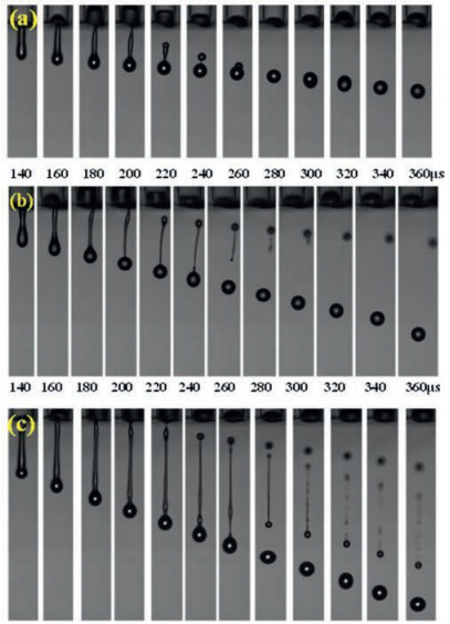
Firstly, we investigated the influence of driving voltage on the ink droplet formation. Fig. 1 shows three typical droplet formation behavior at three driving voltages, 62, 64, 71 V. It is obvious that the droplet could be forced out from the nozzle and formed a single droplet when V = 62 V in Fig. 1a. In Fig. 1b, a primary droplet was formed, followed by a relatively small secondary droplet. When the driving voltage increases to 71 V, it could be found that the ink filament wasn't stable and masses of small satellite droplets were formed following the primary droplet.

|
Download:
|
| Fig. 1. Droplet formation behaviors at three typical driving voltages: (a) 62 V, (b) 64 V, (c) 71 V. | |
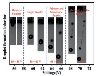
Fig. 2 summarized the types of droplet formation behavior at different printing voltage ranges. When 55 < V ≤ 58 V, the droplet shrank into the nozzle when the droplet was ejected from the nozzle in later times, which indicated that the kinetic energy supplied by the deformation of the piezoelectric transducer was not enough to force the droplet to be jetted from the nozzle. As the driving voltage increases, 58 < V ≤ 63 V, a single and stable droplet could be formed. When 63 < V ≤ 67 V, the primary droplet was formed followed by the secondary droplet. The driving force was excess to supply much more kinetic energy. But the secondary droplet could not catch up with the primary droplet to fuse into a single droplet. When the driving voltage continues to increase, V > 67 V, masses of small satellite dots were formed following the primary droplet. In summary, 58 < V ≤ 63 V is an adequate voltage range to ensure single and stable droplet formation with a pulse time of 38.5 μs.

|
Download:
|
| Fig. 2. Droplet formation behaviors at various driving voltage ranges. | |
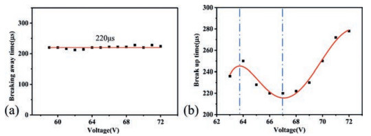
The related droplet behavior parameters in Figs. 1 and 2 were acquired to make a further understanding of the droplet formation process. Fig. 3 shows the breaking away time from the printing nozzle and the break up time of filament at various driving voltages. The breaking away time denotes the time that the filament detaches from nozzle and the break up time denotes the time that the filament break into two droplets. From Fig. 3a, as the voltage increases, the breaking away times from the nozzle were almost unchanged, bumpy around 220 μs, which indicates that the initial droplet action was unaffected by the driving voltage. Fig. 3b shows the fitted curve of the break up time of filament with the driving voltage. With the increase of the driving voltage, the break up time increased firstly, with a peak value at 63.7 V. Then the break up time began to decrease until 67 V, reaching a valley value of 215 μs. In the later times, the break up time increased again until 72 V. The detailed discussion was illustrated in the next section.

|
Download:
|
| Fig. 3. The breaking away time form the nozzle and break up time of the filament vs. the driving voltages: (a) the breaking away time, (b) the break up time. | |
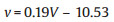
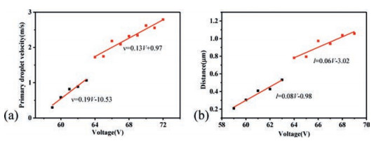
The droplet velocity and droplet distance away from the nozzle of primary droplet at different driving voltages are shown in Fig. 4. By fitting the data linearly, two linear stages were acquired. The two linear equations between the primary velocity (v) and the voltage are as follows:
|
(2) |

|
(3) |

|
Download:
|
| Fig. 4. The primary droplet speed and the distance of the primary droplet variation with the voltage: (a) the primary droplet speed, (b) the distance of the primary droplet. | |
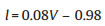
The droplet distances (l) away from the nozzle are also as follows:
|
(4) |
The second stage is
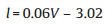
|
(5) |
The velocity and droplet distance of the primary droplet were divided into two stages at nearly 63 V. Fig. 5 illustrates the ligament length and the elongation rate of 158 kDa PFO ink at the voltage of 63 and 67 V with a pulse time of 38.5 μs. The filament length increased gradually until nearly 215 μs at 63 and 67 V. The elongation rate could be acquired by the first order derivative of the filament length. The filament extension rate was nearly constant before 215 μs. But the elongation rate at 63 V and 67 V all showed a trough or minimum, which indicates the filament was contracted with a high speed at this moment. What is different is that there is another trough or minimum for the ink sample at 235 μs at 63 V. That is the reason why the velocity and droplet distance were divided into two stages at 63 V and the break up time showed peak and valley value at 63 V and 67 V.

|
Download:
|
| Fig. 5. The ligament length and speed of extension variation with the time after the droplet emergency: (a) driving voltage: 63 V, pulse time: 38.5 μs; (b) driving voltage: 67 V, pulse time: 38.5 μs. | |
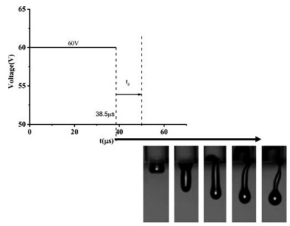
The droplet ejection process is the result of a combined effects of inertial, viscous and capillary forces, promoted by the inertial forces and obstructed by viscous forces and capillary forces. Fig. 6 illustrates the adopted driving waveform and the corresponding droplet ejection process. As shown in Fig. 6, the PFO ink jetting process was operated by the single linear type waveform (60 V with a pulse time of 38.5 μs). When the driving voltage single was applied to the piezoelectric transducer (PZT), the PZT underwent mechanical deformation gradually. There is a delay time (td) for the force due to the PZT mechanical deformation to function on the ejecting ink and the ink droplet cannot be ejected immediately until 50 μs. At the beginning of the ejection, the ink fluid was at the interplay of inertial and capillary forces. The two forces were nearly same for the one kind of ink sample we used when the ink was still stored inside the chamber. That is the reason why the breaking away time from the orifice was nearly the same around 220 μs at different voltage amplitudes in Fig. 3a. The forward momentum was from the pressure pulse. As the ejection went on, the driving forces at each printing condition were different. The viscosity forces were different at different shearing deformations, which results the different droplet formation behaviors.

|
Download:
|
| Fig. 6. The droplet formation and the driving force analysis. | |
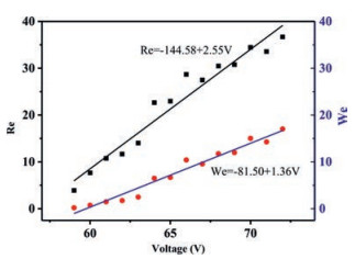
Reynolds number (Re) and Weber number (We) were proposed to illuminate the drop formation dynamics. The Re number is used to characterize the fluid flow, which is the ratio of inertial and viscous forces. The We number denotes the ratio of inertial and capillary forces. Re and We number are defined as follows:

|
(6) |

|
(7) |
where v, α, ρ, η and γ are the droplet velocity, the characteristic dimension (the diameter of the jetting nozzle), the fluid density, viscosity and surface tension of fluid.
Fig. 7 illustrates the Re and We variation of 158 kDa PFO ink with the increasing driving voltages. The data shows that the Re and We value both increased with the increase of the driving voltages. The Re and We value were high at high driving voltages and We number even exceeded 15 at the driving voltage 70 V. The dynamic force functioned on the molecular chain was also high at high driving voltages, which would stretch the molecular chain. The coil–stretch transition of PFO molecular chain occurred, which influences the viscoelasticity of PFO ink seriously.

|
Download:
|
| Fig. 7. The variation of Re and We vs. the driving voltages. | |
For Eq. (1), the elongation rate can be calculated using the following formula:

|
(8) |
where L denotes the journey distance of the main droplet. The coilstretch transition occurs for linear polymers at a critical value Wi = 0.5. The Wi values at different driving voltages were calculated and shown in Fig. 8. It is obvious that the Wi value increases with the increase of the driving voltage. As the printing voltage continues to increase, V > 63 V, the Wi was more than 0.5, which indicated the coil-stretch transition of PFO molecular chain occurs. The stretch of the molecular chain influences the break up behavior of the filament, which results in the formation of satellite droplets. The Wi was less than 0.5 when the driving voltage 58 < V ≤ 63 V, which indicate that the PFO was in a coil state to form a single droplet. The Wi value was 0.41 when driving voltage V = 63 V. That is reason why the single and stable droplet was formed during the voltage range 58 < V ≤ 63 V.

|
Download:
|
| Fig. 8. The Wi variation at different driving voltages. | |
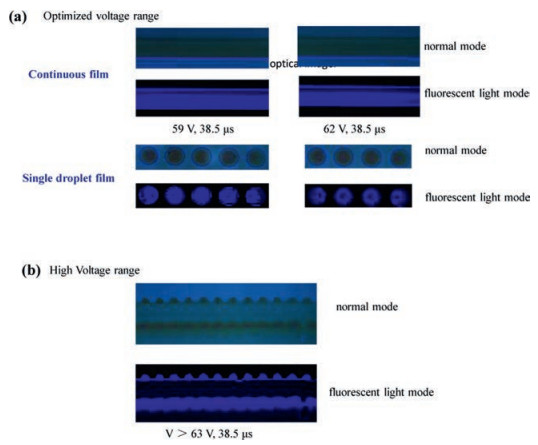
The single droplet and the optimized voltage range were critical in forming a continuous film. Fig. 9 shows the behavior of a single droplet deposition and the film deposition of several single droplets at different driving voltage ranges. As a result, PFO continuous film was obtained on a spin coating PEDOT surface at the driving voltage 59 and 62 V with a pulse time 38.5 μs in Fig. 9a. At the higher voltages V > 63 V, an unregular films with serrulate edges was formed induced by the satellite droplets in Fig. 9b.

|
Download:
|
| Fig. 9. The film deposition at different driving voltage range. | |
In conclusion, we systemically inspected the influence of driving voltage on the droplet formation behavior during inkjet printing. The droplet formation behavior at various driving voltages indicated that 58 ≤ V < 63 V is an adequate voltage range to ensure a single and stable droplet formation with a 38.5 μs pulse time using single waveform for the polyfluorene ink. The breaking away time from the nozzle keeps constant with a 220 μs value despite the increase of the driving voltage. The droplet ejection process contains two stages, first an interplay between the inertial and capillary forces and then viscosity forces dominates in the later times. The filament break up time increased firstly and began to decrease at 63.7 V to reach valley value of 215 μs, but it increased again at 67 V driving voltage. The velocity and droplet distance curves were divided into two stages at 63.0 V. The difference of the filament extension resulted in such a result. At last when V > 63 V, Wi > 0.5, the coil–stretch transition of PFO molecular chain occurred, which leads to the satellite droplet formation at high driving voltages. While the driving voltage V ≤ 63 V, Wi < 0.5, the PFO molecular chain was coiled to guarantee stable and single droplet formation.
Declaration of competing interestThe authors declare that they have no known competing financial interests or personal relationships that could have appeared to influence the work reported in this paper.
AcknowledgmentsThis work was supported by the National Natural Science Foundation of China (Nos. 51873212, 91833306) and National Key R&D Program of "Strategic Advanced Electronic Materials" (Nos. 2016YFB0401301, 2017YFB0404402).
| [1] |
Z. Du, X. Yu, Y. Han, Chin. Chem. Lett. 29 (2018) 399-404. DOI:10.1016/j.cclet.2017.09.031 |
| [2] |
X. Yu, R. Xing, Z. Peng, et al., Chin. Chem. Lett. 30 (2019) 135-138. DOI:10.1016/j.cclet.2018.09.007 |
| [3] |
Z. Ding, R. Xing, Q. Fu, et al., Org. Electron. 12 (2011) 703-709. DOI:10.1016/j.orgel.2011.01.027 |
| [4] |
B.J. de Gans, P.C. Duineveld, U.S. Schubert, Adv. Mater. 16 (2004) 203-213. DOI:10.1002/adma.200300385 |
| [5] |
B. Derby, Inkjet printing of functional and structural materials: fluid property requirements, feature stability, and Resolution, in: D.R. Clarke, M. Ruhle, F. Zok (Eds.), Annual Review of Materials Research, Vol 40, Annual Reviews, Palo Alto, 2010, pp. 395-414.
|
| [6] |
B.J. de Gans, U.S. Schubert, Macromol. Rapid Commun. 24 (2003) 659-666. DOI:10.1002/marc.200350010 |
| [7] |
G.D. Martin, S.D. Hoath, I.M. Hutchings, Iop, Inkjet Printing-the Physics of Manipulating Liquid Jets and Drops, Engineering and Physics-synergy for Success, Iop Publishing Ltd., Bristol, 2008.
|
| [8] |
B. Derby, J. Eur, Ceram. Soc. 31 (2011) 2543-2550. DOI:10.1016/j.jeurceramsoc.2011.01.016 |
| [9] |
O.A. Basaran, H.J. Gao, P.P. Bhat, Annu. Rev. Fluid Mech. 45 (2013) 85-113. DOI:10.1146/annurev-fluid-120710-101148 |
| [10] |
Z. Du, R. Xing, X. Cao, et al., Polymer 115 (2017) 45-51. DOI:10.1016/j.polymer.2017.03.023 |
| [11] |
H.C. Nallan, J.A. Sadie, R. Kitsomboonloha, et al., Langmuir 30 (2014) 13470-13477. DOI:10.1021/la502903y |
| [12] |
R. Xing, T. Ye, Y. Ding, et al., Org. Electron. 10 (2009) 313-319. DOI:10.1016/j.orgel.2008.12.006 |
| [13] |
R. Xing, Y. Xuan, Z. Wang, et al., Curr. Appl. Phys. 9 (2009) 760-763. DOI:10.1016/j.cap.2008.07.005 |
| [14] |
R. Xing, Y. Xuan, D. Ma, Y. Han, J. Vac, Sci. Technol. B 26 (2009) 1-55. |
| [15] |
R. Xing, C. Luo, Z. Wang, Y. Han, Polymer 48 (2007) 3574-3583. DOI:10.1016/j.polymer.2007.04.031 |
| [16] |
S.D. Hoath, I.M. Hutchings, O.G. Harlen, et al., Regimes of Polymer Behaviour in Drop-on-Demand Ink-Jetting, Soc Imaging Science & Technology, Springfield, 2012.
|
| [17] |
S.D. Hoath, J.R. Castrejon-Pita, W.K. Hsiao, et al., J. Imaging Sci. Technol. 57 (2013) 10. |
| [18] |
S.D. Hoath, W.K. Hsiao, S.J. Jung, et al., J. Imaging Sci. Technol. 57 (2013) 11. |
| [19] |
S.D. Hoath, S. Jung, I.M. Hutchings, Phys. Fluid. 25 (2013) 5. |
| [20] |
Z. Du, Y. Lin, R. Xing, et al., Polymer 138 (2018) 75-82. DOI:10.1016/j.polymer.2018.01.052 |
| [21] |
P.G. Degennes, J. Chem. Phys. 60 (1974) 5030-5042. DOI:10.1063/1.1681018 |
| [22] |
B.J. de Gans, L.J. Xue, U.S. Agarwal, U.S. Schubert, Macromol. Rapid Commun. 26 (2005) 310-314. DOI:10.1002/marc.200400503 |
| [23] |
Y.F. Liu, M.H. Tsai, Y.F. Pai, W.S. Hwang, Appl. Phys. A Mater. 111 (2013) 509-516. DOI:10.1007/s00339-013-7569-7 |
| [24] |
K.S. Kwon, M.H. Jang, H.Y. Park, H.S. Ko, Rev. Sci. Instrum. 85 (2014) 065101. DOI:10.1063/1.4879824 |
| [25] |
C. Mei, J. Ding, B. Yao, et al., J. Polym. Sci. Polym. Chem. 45 (2007) 1746-1757. DOI:10.1002/pola.21942 |
| [26] |
M. Wang, H. Tong, Y. Cheng, et al., J. Polym. Sci. Polym. Chem. 48 (2010) 1990-1999. DOI:10.1002/pola.23966 |
| [27] |
M. Yu, S. Wang, S. Shao, et al., J. Mater. Chem. C 3 (2015) 861-869. DOI:10.1039/C4TC02173H |
| [28] |
L. Zhao, S. Wang, S. Shao, et al., J. Mater. Chem. C 3 (2015) 8895-8903. DOI:10.1039/C5TC01711D |