 2020, Vol. 31


b Tianjin Key Laboratory of Organic Solar Cells and Photochemical Conversion, School of Chemistry and Chemical Engineering, Tianjin University of Technology, Tianjin 300384, China
Electrocatalytic water splitting into hydrogen and oxygen represents one of the most promising strategies to store renewable energy and mitigate environmental issues [1-3]. Platinum-based material exhibits excellent hydrogen evolution reaction (HER) performance [4, 5], meanwhile RuO2 and IrO2 are benchmark electrocatalysts for oxygen evolution reaction (OER) [6]. The high price and low abundance of precious metals greatly hamper their practical applications [7, 8]. Furthermore, the use of different catalysts in HER and OER adds a complex process and additional equipment to manufacture electrodes. Therefore, rational design of cheap metal-based catalysts towards OER and HER is highly desirable. The integration of cathode and anode in the same electrolyte cell is beneficial for the enhanced energy efficiency and concurrently reduced manufacturing cost.
Transition metal-based electrocatalysts have attracted intensive interests due to their rich reservoir, and moderate overpotentials for water splitting whatever under both acidic or alkaline conditions [9-11]. For example, CoSe2 nanoparticles exhibited excellent HER performance among first-row transition-metal (e.g., Fe, Co, Ni) dichalcogenides [12]. Molecular orbital theory predicted that CoSe2 acts as a promising OER electrocatalyst to promote rapid proton transfer [13]. The increase of active sites and conductivity is crucial to improve its electrocatalytic performance. Xie and co-workers showed that the OER performance of CoSe2 can be improved by reducing thickness into the atomic scale to expose active edge sites [14]. Kang et al. incorporated carbon nanotubes (CNTs) with CoSe2 microspheres, displaying an HER overpotential of ~174 mV at 10 mA/cm2 in 0.5 mol/L H2SO4 [15]. Despite these advances, the facile fabrication of integrated catalyst of ultrathin CoSe2 nanostructures and conductive networks for overall water splitting still remains a challenge.
Herein, ultrathin CoSe2/CNTs nanocomposites have been prepared by selenization of CNTs decorated Co-MOF nanosheets. The obtained ultrathin CoSe2 is favorable for exposing active sites, and the cable-like CNTs anchored on the CoSe2 nanosheets facilitate the electron-transfer. As expected, the ultrathin CoSe2/CNTs nanocomposites exhibited enhanced performance towards HER and OER compared to bare CoSe2 nanosheets, at low overpotential of 190 mV and 300 mV vs. reversible hydrogen electrode (RHE), respectively. Furthermore, a water electrolyzer equipped with two CoSe2/CNTs electrodes showed good performance at a potential of 1.75 V at 10 mA/cm2 for overall water splitting.
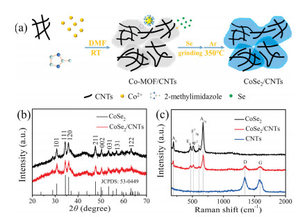
Fig. 1a illustrates the process for the preparation of ultrathin CoSe2/CNTs. Firstly, Co-MOF/CNTs precursor was synthesized by reacting Co2+ with 2-methylimidazole in CNTs dispersion of DMF at room temperature. In this process, the strong electrostatic interaction between Co2+ ions and negative charged CNTs plays a crucial role on the heterogeneous nucleation of Co-MOF crystals on CNTs surface [16]. Subsequently, an in-situ selenization was introduced to convert Co-MOF/CNTs into CoSe2/CNTs under Ar atmosphere at 350 ℃.

|
Download:
|
| Fig. 1. (a) Schematic illustration for the synthesis of CoSe2/CNTs nanocomposites. (b) XRD patterns of CoSe2 and CoSe2/CNTs with the standard pattern of CoSe2 highlighted by sticks. (c) Raman spectra of CoSe2, CoSe2/CNTs and CNTs. | |
The crystalline structures of as-prepared materials were analyzed by X-ray diffraction (XRD). After the selenization of Co-MOF and Co-MOF/CNTs, the Co-MOF samples can be readily transformed to the orthorhombic CoSe2, which well-matched the standard pattern (JCPDS No. 53-0449) (Fig. 1b). Furthermore, Raman spectra as shown in Fig. 1c reveal the CoSe2/CNTs nanocomposites have seven vibration peaks at 195, 471, 514, 605, 671, 1350, and 1591 cm-1, respectively. The strong peaks at 195 and 671 cm-1 are assigned to Ag and A1g modes of CoSe2 [17]. The weak peaks at 471, 514, and 605 cm-1 could be ascribed to Eg, F2g1, and F2g2 modes of CoO/Co3O4, which may be caused by slight oxidation of CoSe2 with trace SeO2 in Se source. Besides, the peaks at 1350 cm-1 (D-band) and 1591 cm-1 (G-band) in the Raman spectra of CoSe2/CNTs are derived from sp3- and sp2-hybridized carbons of CNTs [18, 19], indicating the presence of CNTs. To determine the proportions of each component, the thermogravimetric (TG) curves (Fig. S1a in Supporting information) of CoSe2 and CoSe2/CNTs were recorded under an O2 atmosphere. In the TG curve (Fig. S1a, black line) of bare CoSe2, the initial weight increase at ~460 ℃ and a subsequent weight loss are ascribed to the partial oxidation of CoSe2 and the complete oxidation into Co3O4, respectively. As for the TG curve (Fig. S1a, red line) of CoSe2/CNTs nanocomposites, the first weight increase is not obvious owing to the combustion of CNTs at around 400 ℃. Based on the TG results, the CNTs content in CoSe2/CNTs nanocomposites was estimated to be about 19.4%, showing that the CoSe2 was totally transformed into Co3O4. As shown in Fig. S1b (Supporting information), the XRD patterns of two samples obtained after the TG test are in good agreement with those of pure Co3O4 (JCPDS No. 43-1003).
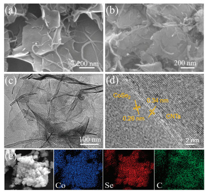
Fig. 2 gives the shape microstructures of the as-prepared Co-MOF/CNTs and CoSe2/CNTs. As shown in Fig. 2a and Figs. S2a-c (Supporting information), the Co-MOF exhibits nanosheets and the CNTs are tightly anchored on the Co-MOF surfaces. After selenization, the Co-MOF/CNTs has been totally converted to CoSe2/CNTs with inherit of original shape (Fig. 2b and Figs. S2d-f in Supporting information). As shown in Fig. S3 (Supporting information), the size of the CoSe2 in the CoSe2/CNT composite is in a range of 100–300 nm, and the diameter of the CNTs is mainly focused on the 25 nm. Transmission electron microscopy (TEM) image in Fig. 2c reveals that the CoSe2 in CoSe2/CNTs displays ultrathin nanosheets and interconnects with CNTs. Corresponding high-resolution TEM (HRTEM) image (Fig. 2d) shows the lattice spacing of 0.26 nm, which can be assigned to the (101) crystal planes of CoSe2, while the lattice spacing of 0.34 nm is for CNTs, confirming the close interaction between CoSe2 and CNTs. The elemental mappings of CoSe2/CNTs (Fig. 2e) show the uniform distribution of Co, Se and the presence of C element. This structure is very favorable for water splitting, where the conductivity could be enhanced by conductive CNTs networks, and the ultrathin feature of CoSe2 could increase the active sites.

|
Download:
|
| Fig. 2. SEM images of Co-MOF/CNTs (a) and CoSe2/CNTs (b). Low-magnification (c) and high-resolution (d) TEM images of as-prepared CoSe2/CNTs. (e) EDS elemental mapping of CoSe2/CNTs. | |
X-ray photoelectron spectroscopy (XPS) was carried out to investigate the chemical composition and the surface electronic state of the as-prepared CoSe2/CNTs. As shown in Fig. S4a (Supporting information), the XPS survey spectrum gives the presence of Co, Se, C and O. The high resolution Co 2p3/2 peak in Fig. S4b (Supporting information) can be deconvoluted into two chemical states at the binding energies of 780.9 eV and 785.4 eV, which are from Co-Se and the shakeup satellite peak, respectively [20, 21]. The Se 3d spectrum of the CoSe2/CNTs (Fig. S4c in Supporting information) shows the core-level band of the Se region, in which the binding energies of Se 3d3/2 and Se 3d5/2 at 55.3 eV and 56.1 eV are coincided with CoSe2, respectively [22]. The peak at around 60.2 eV is associated with SeOx, which may be caused by inevitably slight oxidation of CoSe2 [23], while the peaks in the range of 58–60 eV are attributed to Co 3p at the surface of CoSe2/CNTs [24]. The C1s spectrum in Fig. S4d (Supporting information) presents the peaks of the C element, in which the peaks located at 284.8 eV, 285.6 eV, and 289.6 eV assigned to chemical bonds C–C, C–O, and C=O, respectively [25].
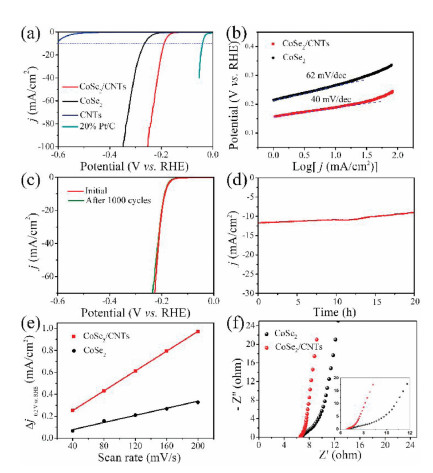
The electrocatalytic HER performance of the as-prepared catalysts was evaluated in 1 mol/L KOH solution with a typical three-electrode system. Fig. 3a shows their linear sweep voltammograms (LSV) lines with a scan rate of 10 mV/s. CoSe2/CNTs required a lower overpotential (η = 190 mV vs. RHE) to achieve the current density of 10 mA/cm2 with respect to bare CoSe2 (η =266 mV vs. RHE), which is better than most reported CoSe2-based eletrocatalysts (Table S1 in Supporting information). No HER activity was observed over CNTs. Additionally, the electrocatalytic activities of CoSe2/CNTs with different CNTs contents were systematically investigated. As shown in Fig. S5a (Supporting information), the introduction of CNTs could boost the electrochemical performance effectively. With the increase of CNTs to 5 mg, the CoSe2/CNTs exhibits overpotential of 190 mV, which ismuch lowerthan thoseof CoSe2/CNTs-3 mg (194 mV) and CoSe2/CNTs-8 mg (208 mV), respectively. Fig. 3b compares the Tafel slopes of CoSe2/CNTs and bare CoSe2.The Tafel slopeover CoSe2/CNTs(40 mV/dec) ismuch smaller than that of bare CoSe2 (62 mV/dec), indicating that the HER rate on CoSe2/CNTs would be more rapidly than bare CoSe2. Electrochemical impedance spectroscopy (EIS) spectra (Fig. 3f) also confirm that CoSe2/CNTs possessed a lower Rct value than bare CoSe2. Thus the small Tafel slope and Rct value verify the accelerated reaction kinetics and enhanced conductivity over CoSe2/CNTs. The synergistic effect between CoSe2 and CNTs should result in the enhanced electrocatalytic activity, in which CoSe2 is responsible for the HER activity, and CNTs anchored on CoSe2 nanosheets offers conductive channels. Moreover, as shown in Figs. 3c and d, both LSV polarization curve after 1000 cycles and continuous amperometric i-t test for 20 h indicate its superior stability.

|
Download:
|
| Fig. 3. (a) LSV polarization curves of HER for CoSe2/CNTs, CoSe2, CNTs, and Pt/C, in 1 mol/L KOH at a scan rate of 10 mV/s. (b) The corresponding Tafel plots of CoSe2 and CoSe2/CNTs. (c) LSV polarization curves recorded at CoSe2/CNTs electrode with a sweep rate of 10 mV/s before and after 1000 consecutive cycles between -0.4 V and +0.3 V vs. RHE at 100 mV/s (with iR compensated). (d) Time-dependent current density curves of the CoSe2/CNTs under a static potential of -0.16 V vs. RHE for 20 h. (e) The plots of corresponding current density against scan rate over CoSe2 and CoSe2/CNTs. (f) EIS Nyquist plots of CoSe2 and CoSe2/CNTs. | |
In order to further understand the enhanced catalytic activity, the electrochemical active surface areas of CoSe2/CNTs and CoSe2 were estimated from the cyclic voltammetry (CV) at various scan rates in a potential rage of 0.1–0.2 V. As shown in Fig. S6 (Supporting information), all the CV curves of two samples are almost rectangular, indicating their ideal capacitive behaviors in electrochemical reactions [26-28]. As revealed in Fig. 3e, a linear trend was acquired in the corresponding current density against scan rate plots for both CoSe2 and CoSe2/CNTs, and the capacitance values (Cdl) can be derived from the slope of the linear region. Obviously, CoSe2/CNTs has a larger Cdl of 4.5 mF/cm2 compared to CoSe2 (1.6 mF/cm2), indicating CoSe2/CNTs possesses larger electrochemical surface area with more active sites than bare CoSe2. In addition, the electrochemically active surface area (ESCA) values of the CoSe2/CNTs and CoSe2 are determined to be 7.95 cm-2 and 2.83 cm-2, respectively. Intrinsic HER activity of the CoSe2/CNTs and CoSe2 was normalized by ESCA at 10 mV/s (Fig. S7 in Supporting information), the introduction of cable-like CNTs greatly improve the intrinsic HER activity.
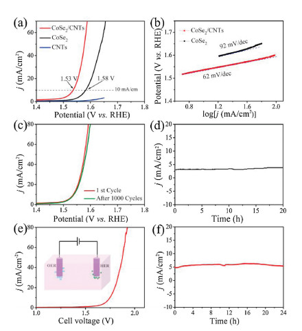
The OER performance of CoSe2/CNTs was evaluated in 1 mol/L KOH saturated with O2. Fig. 4a gives the corresponding polarization curves, showing that CoSe2/CNTs requires a low overpotential of 300 mV to achieve 10 mA/cm2 with respect to bare CoSe2 (350 mV). The value is also superior to many reported CoSe2-based eletrocatalysts (Table S2 in supporting information). The intrinsic kinetic of OER was verified by calculating the Tafel slopes of catalysts on polarizationcurves (Fig. 4b), inwhich CoSe2/CNTs shows the smaller Tafel slope of 62 mV/dec than CoSe2 (92 mV/dec). Fig. S5b (Supporting information) shows the OER overpotentials of the CoSe2 with different contents of CNTs. It can be seen that lower CNTs content is not enough for the construction of conductive network, while excessive use of CNTs is not conducive to the exposure of active sites. Therefore, a moderate ratio of CNTs to CoSe2 isvitalto realizea desirable electrochemical performance.To test the stability of CoSe2/CNTs for OER, the LSV polarization curves of CoSe2/CNTs electrode before and after 1000 consecutive cycles were recorded (Fig. 4c). After 1000 CV scans, the LSV curve of CoSe2/CNTs increased by only 10 mV even at current density of 80 mA/cm2 compared with the original one. Meanwhile, the electrocatalytic activity can be maintained at least 20h at a static potential of 1.5V vs. RHE, indicating its good stability for OER (Fig. 4d). The chemical changes of CoSe2/CNTs nanocomposites during the OER reaction were investigated by corresponding XPS measurements. As shown in Fig. S8 (Supporting information), the intensity of Co-Se bonds was decreased after OER, while the signal of Co-O bonds at high binding energies increased greatly, implying the in-situ formation of cobalt oxides or CoOOH including high valence Co(Ⅲ) or Co(Ⅳ) ions during the OER process [29, 30]. The XPS analysis of the CoSe2/CNTs nanocomposites after OER cycling shows that intermediate of CoOOH was in-situ formed on the CoSe2 surface during the reaction.

|
Download:
|
| Fig. 4. (a) LSV polarization curves of OER for CoSe2/CNTs, CoSe2 and CNTs in 1 mol/L KOH at scan rate of 10 mV/s; (b) the corresponding Tafel plots of CoSe2 and CoSe2/CNTs. (c) LSV polarization curves recorded at CoSe2/CNTs electrode with a sweep rate of 10 mV/s before and after 1000 consecutive cycles between +0.9 V and +1.8 V vs. RHE at 100 mV/s (with iR compensated). (d) Time-dependent current density curves of the CoSe2/CNTs under a static potential of +1.5 V vs. RHE for 20 h. (e) Polarization curves recorded at a scan rate of 10 mV/s in a two-electrode CoSe2/CNTs-based water electrolyzer. (f) Time-dependent current density curves of the CoSe2/CNTs-based water electrolyzer under a static potential of 1.71 V for 24 h. | |
For practical applications, we further examined its overall water splitting performance. Fig. S9 (Supporting information) shows the LSV polarization curves of the HER and OER in 1 mol/L KOH over CoSe2/CNTs electrode. The onset potentials towards HER and OER are -114 mV and +1302 mV vs. RHE, respectively. In a two-electrode CoSe2/CNTs-based water electrolyzer, the overall reaction reachedat a cellvoltage of 1.75 V at 10 mA/cm2 (Fig. 4e), which is better than other reported similar materials (Table S3 in Supporting information). The long-term testat 1.71 V showed good stability of CoSe2/CNTs electrode for water splitting (Fig. 4f).
In summary, we have developedan in-situ selenization route for the conversion of CNTs decorated Co-MOF nanosheets to ultrathin CoSe2/CNTs nanocomposites. Since the synergistic effect between ultrathin CoSe2 nanosheets with exposed active sites and CNTs with improved conductivity, the CoSe2/CNTs nanocomposites exhibited good electrocatalytic activity and durability for HER and OER. Furthermore, as a bifunctional electrocatalyst, it also exhibited good overall water splitting performance. The present work provides a strategy for the fabrication of electrocatalysts for water splitting and alternative applications.
Declaration of competing interestThe authors declare that they have no known competing financial interests or personal relationships that could have appeared to influence the work reported in this paper.
AcknowledgmentsThe authors gratefully acknowledgethe financial support by the National Natural Science Foundation of China (No. 21771137), the Key Project of Natural Science Foundation of Tianjin (No. 18JCZDJC97200), the Training Project of Innovation Team of Colleges and Universities in Tianjin (No. TD13-5020), and the start-up fund of Qilu University of Technology, Shandong Academy of Sciences.
Appendix A. Supplementary dataSupplementary material related to this article can be found, in the online version, at doi:https://doi.org/10.1016/j.cclet.2020.02.029.
| [1] |
C. Hu, L. Zhang, J. Gong, Energy Environ. Sci. 12 (2019) 2620-2645. DOI:10.1039/C9EE01202H |
| [2] |
X.X. Chen, X.J. Zhen, H.Y. Gong, et al., Chin. Chem. Lett. 30 (2019) 681-685. DOI:10.1016/j.cclet.2018.09.017 |
| [3] |
H. Zhou, Y. Wang, R. He, et al., Nano Energy 20 (2016) 29-36. DOI:10.1016/j.nanoen.2015.12.008 |
| [4] |
S. Bai, C. Wang, M. Deng, et al., Angew. Chem. Int. Ed. 53 (2014) 12120-12124. DOI:10.1002/anie.201406468 |
| [5] |
N. Cheng, S. Stambula, D. Wang, et al., Nat. Commun. 7 (2016) 13638. DOI:10.1038/ncomms13638 |
| [6] |
Y. Lee, J. Suntivich, K.J. May, E.E. Perry, Y. Shao-Horn, J. Phys, Chem. Lett. 3 (2012) 399-404. |
| [7] |
D. Kiriya, P. Lobaccaro, H.Y.Y. Nyein, et al., Nano Lett. 16 (2016) 4047-4053. DOI:10.1021/acs.nanolett.6b00569 |
| [8] |
G.J. Wei, Z.J. Wang, X.X. Zhao, et al., Mater. Res. Express 2 (2014) 015501. DOI:10.1088/2053-1591/2/1/015501 |
| [9] |
J. Ran, J. Zhang, J. Yu, M. Jaroniec, S.Z. Qiao, Chem. Soc. Rev. 43 (2014) 7787-7812. DOI:10.1039/C3CS60425J |
| [10] |
D.D. Wang, Y.Q. Zou, L. Tao, et al., Chin. Chem. Lett. 30 (2019) 826-838. DOI:10.1016/j.cclet.2019.03.051 |
| [11] |
D. Merki, X. Hu, Energy Environ. Sci. 4 (2011) 3878-3888. DOI:10.1039/c1ee01970h |
| [12] |
D.H. He, X.L. Wu, W. Liu, et al., Chin. Chem. Lett. 30 (2019) 229-233. DOI:10.1016/j.cclet.2018.03.020 |
| [13] |
J. Suntivich, K.J. May, H.A. Gasteiger, J.B. Goodenough, Y. Shao-Horn, Science 6061 (2011) 1383-1385. |
| [14] |
Y. Liu, H. Cheng, M. Lyu, et al., J. Am. Chem. Soc. 136 (2014) 15670-15675. DOI:10.1021/ja5085157 |
| [15] |
J.K. Kim, G.D. Park, J.H. Kim, S.K. Park, Y.C. Kang, Small 13 (2017) 1700068. DOI:10.1002/smll.201700068 |
| [16] |
G.J. Wei, Z. Zhou, X.X. Zhao, W.Q. Zhang, C.H. An, ACS Appl. Mater. Interfaces 10 (2018) 23721-23730. DOI:10.1021/acsami.8b04026 |
| [17] |
S. Peng, X. Han, L. Li, et al., Small 12 (2016) 1359-1368. DOI:10.1002/smll.201502788 |
| [18] |
R.J. Wu, M. Liu, Y.W. Peng, et al., Chin. Chem. Lett. 30 (2019) 989-994. DOI:10.1016/j.cclet.2019.02.021 |
| [19] |
H. Yuan, J. Li, C. Yuan, Z. He, ChemElectroChem 1 (2014) 1828-1833. DOI:10.1002/celc.201402150 |
| [20] |
S.K. Park, J.K. Kim, Y.C. Kang, Chem. Eng. J. 328 (2017) 546-555. DOI:10.1016/j.cej.2017.07.079 |
| [21] |
G.D. Park, Y.C. Kang, Chem. Eur. J. 22 (2016) 4140-4146. DOI:10.1002/chem.201504398 |
| [22] |
C. Xia, Q. Jiang, C. Zhao, M.N. Hedhili, H.N. Alshareef, Adv. Mater. 28 (2016) 77-85. DOI:10.1002/adma.201503906 |
| [23] |
D. Kong, H. Wang, Z. Lu, Y. Cui, J. Am. Chem. Soc. 136 (2014) 4897-4900. DOI:10.1021/ja501497n |
| [24] |
Y.Y. Yao, H.J. Chao, T.H. Chou, et al., Sol. Energy 137 (2016) 401-408. DOI:10.1016/j.solener.2016.08.040 |
| [25] |
S.H. Choi, Y.C. Kang, Nanoscale 8 (2016) 4209-4216. DOI:10.1039/C5NR07733H |
| [26] |
N. Kaeffer, M. Chavarot-Kerlidou, V. Artero, Acc. Chem. Res. 48 (2015) 1286-1295. DOI:10.1021/acs.accounts.5b00058 |
| [27] |
H. Zhang, Y. Li, G. Zhang, et al., J. Mater. Chem. A 3 (2015) 6306-6310. DOI:10.1039/C5TA00707K |
| [28] |
X. Zhao, W. Wang, Z. Hou, et al., Inorg. Chem. Front. 6 (2019) 473-476. DOI:10.1039/C8QI01143E |
| [29] |
Y. Zhang, Y. Qiu, X. Ji, et al., ChemSusChem 12 (2019) 3792-3800. DOI:10.1002/cssc.201901628 |
| [30] |
Y. Chen, S. Xu, S. Zhu, et al., Nano Res. 12 (2019) 2259-2267. DOI:10.1007/s12274-019-2304-0 |