 2020, Vol. 31


2 Department of Orthopaedic Surgery, Renmin Hospital of Wuhan University, Wuhan 430060, China;
c Suzhou Institute of Wuhan University, Suzhou 215123, China
With increasing contradiction between energy demands and environment problems, it is highly desirable to develop clean energy as alternatives to traditional fossil fuels [1-5]. Hydrogen is considered as one of the most promising energy carrier due to its high specific energy density and zero carbon emission [6-8]. Electrochemical water splitting is an efficient and clean way to produce hydrogen with high purity [9-12], while the anodic oxygen evolution reaction (OER) with complicated multistep proton-coupled four-electron transfer process and sluggish oxygen–oxygen bonds formation, still limits the overall energyconvent efficiency [13-15]. Although precious metal or metal oxides (mostly Ir or Ru) is considered as the benchmarking OER catalysts, their scarcity and high cost severely limit their practical applications [16-18]. Consequently, it is greatly attractive to investigate highly efficient and cost-effective precious-metal-free OER electrocatalysts, but still remains a great challenge [19-21].
Recently, nickel-iron based electrocatalysts have been widely investigated owing to its superior OER activity, easy access, and great stability [22, 23]. For example, Dai's group reported ultrathin nickel-iron layered double hydroxide nanoplates on mildly oxidized multiwalled carbon nanotubes (NiFe-LDH@CNT) with an overpotential of 290 mV to obtain the current density of 10 mA/cm2 toward OER in 0.1 mol/L KOH [24]. Liang et al. synthesized a hierarchical Ni-Fe oxyhydroxide@NiFe alloy nanowire array by a modified one-step chemical-deposition method under uniform electromagnetic field for large current density water splitting [25]. Qu and co-workers reported the synthesis of nanosized NiFeP and its OER performance with an overpotential of 270 mV to achieve 10 mA/cm2 in 1.0 mol/L potassium hydroxide [26]. Zhang's group reported anionic-regulated NiFe oxysulfides as OER electrocatalysts with an overpotential of 286 mV at 10 mA/cm2 in alkaline condition [27]. Our group reported three-dimensional (3D) mesoporous nickel-iron selenide with rose-like microsphere architecture possessing superior OER activity of 271 mV to achieve 10 mA/cm2 in alkaline media [28]. Many researches have revealed that nickel borides or iron borides showed great tendency towards water oxidation due to their unique electronic structure and apparent metallicity [29, 30]. Recently, our group reported a unique structure of an amorphous cobalt borate nanosheet-coated cobalt boride (Co-B@Co-Bi) hybrid with 291 mV under a current density of 10 mA/cm2 toward OER in alkaline condition [31]. Despite great efforts have been made, the obtained electrocatalytic performances are still far lower than the benchmarked RuO2/IrO2. More critically, NiFe-based borates (or borides) towards OER reaction has been rarely studied.
Here, inspired by the previous works, we reported the synthesis of a core-shell like catalyst of amorphous nickel-iron boride coated nickel-iron borate (NiFeB@NiFeBi) through a facile sodium borohydride (NaBH4) reduction approach. As expected, the amorphous NiFeB@NiFeBi exhibits remarkable oxygen evolution activity with an overpotential of 237 mV at 10 mA/cm2 and a rather low Tafel slope of 57.65 mV/dec, outperforming the state-of-the-art IrO2 catalyst and most of documented precious-metal-free OER electrocatalysts.
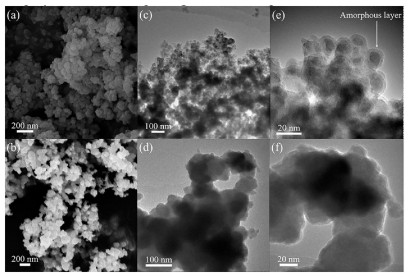
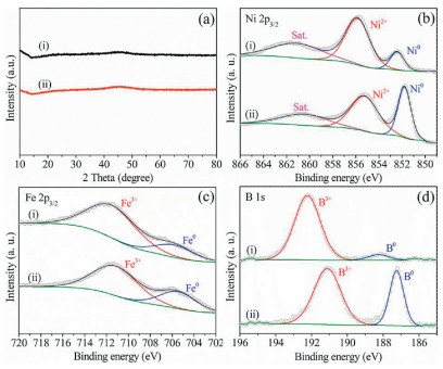
The amorphous NiFeB@NiFeBi was synthesized through a simple and cost-effective in situ chemical reduction method by adding a mixture solution of nickel(II) chloride (NiCl2) and iron(II) chloride (FeCl2) into aqueous solution of sodium borohydride (NaBH4) (Supporting information for details). For comparison, NiFeB was also prepared by adding the solution of NaBH4 into the same amount of NiCl2 and FeCl2 solution through the traditional approach. As displayed in Figs. 1a–d, similar 3D morphologies of NiFeB@NiFeBi and NiFeB fabricated by polydisperse nanoparticles were investigated from scanning electron microscopy (SEM) and transmission electron microscopy (TEM) images. The core-shell morphology of NiFeB@NiFeBi can be observed unambiguously from the high-resolution TEM image shown in Fig. 1e, indicating a thick amorphous layer of NiFeBi coating on the surface of NiFeB. However, aggregated nanoparticles with the range of about 50 nm were observed from the TEM of NiFeB as shown in Fig. 1f, which is similar to the previous report [32]. Furthermore, the selected area electron diffraction (SAED) images further indicate the amorphous structures of NiFeB@NiFeBi and NiFeB (Fig. S1 in Supporting information). In addition, as shown in Fig. 2a, no obvious diffraction peaks in the powder X-ray diffraction (XRD) can be observed, further suggesting the amorphous states of the as-synthesized catalysts. Moreover, the as-obtained NiFeB@NiFeBi was further annealed at 800 ℃ (named as NiFeB@NiFeBi-800) and the resultant XRD shown in Fig. S2 (Supporting information) demonstrated identical pattern of Ni3(BO3)2 (PDF No. 26-1284). For comparison, we synthesized a series of NiFeB@NiFeBi-X (X means the percentage of Fe in the total metal precursors) via varying the feeding molar ratios of Ni/Fe. In addition, the NiB@NiBi and FeB@FeBi were also synthesized through the similar method. Their SEM/TEM images and XRD results are displayed in Figs. S3–S10 (Supporting information). It should be noted that all the prepared NiFeB@NiFeBi-X displayed similar morphologies and amorphous structures.

|
Download:
|
| Fig. 1. SEM images of (a) NiFeB@NiFeBi and (b) NiFeB. TEM images of (c, e) NiFeB@NiFeBi and (d, f) NiFeB. | |
X-ray photoelectron spectroscopy (XPS) was further used to characterize the chemical states of NiFeB@NiFeBi and NiFeB. The XPS survey results (Fig. S11 and Table S1 in Supporting information) suggest the Ni, Fe, B and O are coexisted. The inductively coupled plasma atomic emission spectroscopy (ICP-AES) results (Table S2 in Supporting information) indicated the atomic ratios of Ni, Fe and B are 1:0.18:0.90 for NiFeB@NiFeBi and 1:0.20:0.59 for NiFeB, which is in consistent with the feeding ratios. In the Ni 2p3/2 spectra of NiFeB@NiFeBi (Fig. 2b), two obvious peaks of Ni0 and Ni2+ located at 852.3 eV and 855.8 eV can be observed, with positive shift of about 0.2 eV compared to those in NiFeB, suggesting electron transfer and synergistic effect between NiFeB core and NiFeBi shell. In the Fe 2p3/2 region, similar positive shift about 0.2 eV can be also observed. The peaks located at 711.9 eV and 705.6 eV can be assigned to Fe3+ and Fe0 for NiFeB@NiFeBi, while these peaks were located at 711.7 eV and 705.4 eV for NiFeB (Fig. 2c). As shown in Fig. 2d, the B 1s spectra of both samples showed two distinct peaks. For NiFeB, the peak located at 187.5 eV can be assigned to the B signal in metal boride, indicating the presence of nickel borides. The peak at higher binding energy 191.7 eV can be attributed to the B—O bonding in borate or boron oxide. However, these peaks exhibit positive shifts of about 0.6 eV in NiFeB@NiFeBi. This result suggests the electron transfer from NiFeB core to NiFeBi shell, thus modifying the electron structure of NiFeB@NiFeBi and promoting its OER activity (vide infra) [33]. As shown in the O 1s region (Fig. S12 in Supporting information), three peaks located at 530.4, 531.1 and 532.2 eV can be observed, corresponding to the binding energy of lattice oxygen, substituted hydroxyl species and surface oxygen, respectively [34]. However, only substituted hydroxyl species and surface oxygen peaks can be observed in NiFeB@NiFeBi.

|
Download:
|
| Fig. 2. (a) XRD patterns of (i) NiFeB@NiFeBi and (ii) NiFeB; High resolution XPS spectra of (b) Ni 2p3/2, (c) Fe 2p3/2, (d) B 1s of (i) NiFeB@NiFeBi and (ii) NiFeB. | |
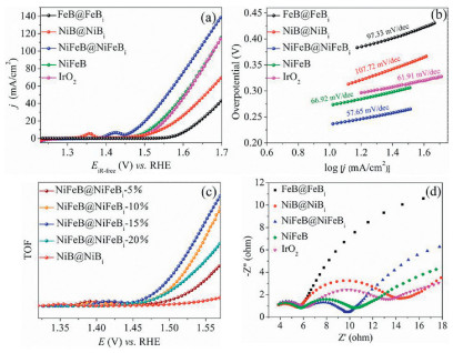
The electrocatalytic activities of NiFeB@ NiFeBi, NiFeB, NiB@NiBi and FeB@FeBi catalysts, as well as commercial IrO2, were tested in the 1.0 mol/L KOH electrolyte using a three-electrode system (pH 13.6). Those catalysts were deposited onto the glass carbon electrode (GCE) to evaluate them OER activity and the catalyst loading was 0.306 mg/cm2. Polarization curves were recorded from linear sweep voltammetry (LSV) test with a scan rate of 1.0 mV/s. In order to eliminate the effect of ohmic resistance, we conducted an iR correction to all raw data in the further discussions. Firstly, we dig out the most suitable nickel to iron ratios of NiFeB@NiFeBi-X. As shown in Figs. S13 and S14 (Supporting information), the best OER performance catalyst is NiFeB@NiFeBi-15% and we further continued the experiments with this sample. As shown in Fig. 3a, NiFeB@NiFeBi shows the best performance in those catalysts with an overpotential of 237 mV to drive a current density of 10 mA/cm2 (η10 = 237 mV), which is much lower than that of NiFeB (η10 = 273 mV), NiB@NiBi (η10 = 303 mV), FeB@FeBi (η10 = 373 mV) and IrO2 (η10 = 287 mV). In addition, the OER activity of annealed NiFeB@NiFeBi-800 was also tested and it showed much lower OER activity than the amorphous NiFeB@NiFeBi, further highlighting the key role of amorphous state of NiFeBi in facilitating the OER process (Fig. S15 in Supporting information). It is worth noting that the OER catalytic activity of NiFeB@NiFeBi is among the top of the reported metal borates/ borides and higher than most of the reported metal-metalloid-based electrocatalysts as indicated in Table S3 (Supporting information). To investigate the catalytic kinetics, the Tafel slopes were calculated as shown in Fig. 3b, demonstrating that NiFeB@NiFeBi exhibited the most favorable OER dynamics, suggesting that the introduction of iron dominated the improvement of the overall OER process [35, 36]. In addition, we calculated the TOFs of NiFeB@NiFeBi across the OER region (Fig. S16 and details of the TOF calculation in Supporting information) [37, 38]. As shown in Fig. 3c, the iron species can significantly increase the catalytic performance of NiB@NiBi [39, 40]. However, a larger ratio of iron in the NiFe hybrid may lower the number of actual Ni site and result in the decrease of the overall OER activity. In addition, electrochemical impedance spectroscopy (EIS) was carried out to evaluate the charge transfer resistance during OER process. As shown in Fig. 3d, the Nyquist plot of NiFeB@NiFeB shows the smallest semicircle diameter, suggesting the fastest charge transfer because of the lowest resistance of charge transfer (Rct) [41]. The small Tafel slope and Rct of NiFeB@NiFeBi suggest the fast reaction kinetics under the OER conditions, which should be attributed to bimetallic cores with favorable electronic conductivity as well as the amorphous NiFeBi nanosheets with higher intrinsic activity. In addition, both 2000 CV cycling test and chronopotentiometry results suggest the superior stability of the NiFeB@NiFeBi in alkaline media. As illustrated in the Fig. S17 (Supporting information), after the continuously cyclic voltammetry (CV) scanning for 2000 cycles with a range of 1.2–1.7 V (vs. RHE), a slight positive shift of η10 from the linear sweep voltammetry (LSV) curve is observed, which is also in correspondence with the chronopotentiometry results.

|
Download:
|
| Fig. 3. (a) LSV curves (with iR-correction) for FeB@FeBi, NiB@NiBi, NiFeB@NiFeBi, NiFiB, and IrO2 with a scan rate of 1 mV/ s for OER in 1 mol/L KOH. (b) Tafel plots for FeB@FeBi, NiB@NiBi, NiFeB@NiFeBi, NiFeB and IrO2. (c) TOFs of NiFeB@NiFeBi-X and NiB@NiBi. (d) Nyquist plot of FeB@FeBi, NiB@NiBi, NiFeB@NiFeBi, NiFeB and IrO2. | |
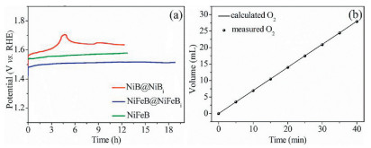
For comparison, the stability test of the NiFeB and NiB@NiBi were also conducted. As shown in Fig. 4a, they are both inferior to NiFeB@NiFeBi. Characterizations of NiFeB@NiFeBi after OER stability test indicate the well-maintained morphology from SEM and TEM images (Figs. S18 and S19 in Supporting information). Furthermore, for the high-resolution Ni 2p spectra (Fig. S20 in Supporting information), the Ni0 on the surface was transformed to Ni2+ after the OER process, which was similar to the previous reports. The B 1s and Fe 2p spectra were kept unchanged, suggesting the core-shell architecture is maintained well (Figs. S21 and S22 in Supporting information). For the high-resolution O spectra, absorbed oxygen indicates that activity O spices was formed and attached onto the surface of the catalyst (Fig. S23 in Supporting information). However, after the OER test, the XPS results indicate that the NiFeB would transform into NiFeBi and its original structure might be destroyed, which is contributed to its much inferior stability to NiFeB@NiFeBi. Besides, the Faraday efficiency of NiFeB@NiFeBi was estimated via quantifying O2 gases produced during the electrolysis, which fitting well with the theoretical yields with the molar ratio O2, corresponding to a Faraday efficiency of almost 99.0% (Fig. 4b).

|
Download:
|
| Fig. 4. (a) Chronopotentiometry curves for NiB@NiBi, NiFeB@NiFeBi, and NiFeB at 10 mA/cm2 in 1 mol/L KOH. (b) Faraday efficiency of O2 production for NiFeB@NiFeBi. | |
In summary, a series of amorphous nickel-iron boride coated nickel-iron borate (NiFeB@NiFeBi-X) electrocatalysts have been successfully fabricated through a simple sodium borohydride reduction approach. The as-obtained NiFeB@NiFeBi exhibits remarkable OER activity under alkaline media, with an overpotential of 237 mV to achieve the current density of 10 mA/cm2 and long-term durability. The XPS and TOFs results indicated that the unique core-shell structure and the electron transfer between the core and shell are contributed to the excellent OER activity of NiFeB@NiFeBi. This work might provide a new way for developing advanced metal borates based electrocatalysts for OER and beyond.
Declaration of competing interestThe authors declare that they have no known competing financial interests or personal relationships that could have appeared to influence the work reported in this paper.
AcknowledgmentsThis work was financially supported by the National Natural Science Foundation of China (No. 21972107), the National Natural Science Foundation of Jiangsu Province (No. BK20191186), and the Large-Scale Instrument and Equipment Sharing Foundation of Wuhan University.
Appendix A. Supplementary dataSupplementary material related to this article can be found, in the online version, at doi:https://doi.org/10.1016/j.cclet.2020.03.009.
| [1] |
C.C. McCrory, S. Jung, J.C. Peters, T.F. Jaramillo, J. Am. Chem. Soc. 135 (2013) 16977-16987. DOI:10.1021/ja407115p |
| [2] |
B. Wang, X. Cui, J. Huang, R. Cao, Q. Zhang, Chin. Chem. Lett. 29 (2018) 1757-1767. DOI:10.1016/j.cclet.2018.11.021 |
| [3] |
Z. Li, H. He, H. Cao, et al., Appl. Catal. B:Environ. 240 (2019) 112-121. DOI:10.1016/j.apcatb.2018.08.074 |
| [4] |
N. Yao, P. Li, Z. Zhou, et al., Adv. Energy Mater 9 (2019) 1902449. DOI:10.1002/aenm.201902449 |
| [5] |
H. Yuan, L. Kong, T. Li, Q. Zhang, Chin. Chem. Lett. 28 (2017) 2180-2194. DOI:10.1016/j.cclet.2017.11.038 |
| [6] |
Y. Zheng, Y. Jiao, A. Vasileff, S.Z. Qiao, Angew. Chem. Int. Ed. 57 (2018) 7568-7579. DOI:10.1002/anie.201710556 |
| [7] |
Y. Men, P. Li, J. Zhou, et al., ACS Catal. 9 (2019) 3744-3752. DOI:10.1021/acscatal.9b00407 |
| [8] |
D. He, X. Wu, W. Liu, et al., Chin. Chem. Lett. 30 (2019) 229-233. |
| [9] |
R. Subbaraman, D. Tripkovic, K.C. Chang, et al., Nat. Mater. 11 (2012) 550-557. DOI:10.1038/nmat3313 |
| [10] |
M. Wang, M. Wang, Y. Fu, S. Shen, Chin. Chem. Lett. 28 (2017) 2207-2211. DOI:10.1016/j.cclet.2017.11.037 |
| [11] |
C. Du, L. Yang, F. Yang, G. Cheng, W. Luo, ACS Catal. 7 (2017) 4131-4137. DOI:10.1021/acscatal.7b00662 |
| [12] |
N. Yao, P. Li, Z. Zhou, et al., Small 15 (2019) 1901993. DOI:10.1002/smll.201901993 |
| [13] |
Q. Yin, J. Tan, C. Besson, et al., Science 328 (2010) 342-345. DOI:10.1126/science.1185372 |
| [14] |
J. Suntivich, K.J. May, H.A. Gasteiger, J.B. Goodenough, Shao-Horn Y., Science 334 (2011) 1383-1385. DOI:10.1126/science.1212858 |
| [15] |
Y. Jiao, Y. Zheng, M. Jaroniec, S. Qiao, Chem. Soc. Rev. 44 (2015) 2060-2086. DOI:10.1039/C4CS00470A |
| [16] |
L. Fu, F. Yang, C. Cheng, W. Luo, Nanoscale 10 (2018) 1892-1897. DOI:10.1039/C7NR09377B |
| [17] |
K. Sardar, E. Petrucco, C.I. Hiley, et al., Angew. Chem. Int. Ed. 53 (2014) 10960-10964. DOI:10.1002/anie.201406668 |
| [18] |
L. Fu, C. Cheng, W. Luo, J. Mater. Chem. A 5 (2017) 24836-24841. DOI:10.1039/C7TA08982A |
| [19] |
T. Liu, F. Yang, G. Cheng, W. Luo, Small 14 (2018) 1703748. DOI:10.1002/smll.201703748 |
| [20] |
X. Cao, X. Zang, X. Zhou, M. Chen, Y. Ding, Chin. Chem. Lett. 29 (2018) 811-814. DOI:10.1016/j.cclet.2017.12.010 |
| [21] |
C. Dong, T. Kou, H. Gao, Z. Peng, Z. Zhang, Adv. Energy Mater. 8 (2018) 1701347. DOI:10.1002/aenm.201701347 |
| [22] |
K. Fominykh, P. Chernev, I. Zaharieva, et al., ACS Nano 9 (2015) 5180-5188. DOI:10.1021/acsnano.5b00520 |
| [23] |
L. Zeng, L. Yang, J. Lu, W. Zhou, et al., Chin. Chem. Lett. 29 (2018) 1875-1878. DOI:10.1016/j.cclet.2018.10.026 |
| [24] |
M. Gong, Y. Li, H. Wang, et al., J. Am. Chem. Soc. 135 (2013) 8452-8455. DOI:10.1021/ja4027715 |
| [25] |
C. Liang, P. Zou, A. Nairan, et al., Energy Environ. Sci. 13 (2020) 86-95. DOI:10.1039/C9EE02388G |
| [26] |
Z. Liu, G. Zhang, K. Zhang, H. Liu, J. Qu, ACS Sustain. Chem. Eng. 6 (2018) 7206-7211. DOI:10.1021/acssuschemeng.8b00471 |
| [27] |
B. Li, S. Zhang, C. Tang, X. Cui, Q. Zhang, Small 13 (2017) 1700610. DOI:10.1002/smll.201700610 |
| [28] |
J. Yu, G. Cheng, W. Luo, Nano Res. 11 (2018) 2149-2158. DOI:10.1007/s12274-017-1832-8 |
| [29] |
J. Masa, P. Weide, D. Peeters, et al., Adv. Energy Mater. 6 (2016) 1502313. DOI:10.1002/aenm.201502313 |
| [30] |
J. Masa, I. Sinev, H. Mistry, et al., Adv. Energy Mater. 7 (2017) 1700381. DOI:10.1002/aenm.201700381 |
| [31] |
T. Tan, P. Han, H. Cong, G. Cheng, W. Luo, ACS Sustain. Chem. Eng. 7 (2019) 5620-5625. DOI:10.1021/acssuschemeng.9b00258 |
| [32] |
H. Li, P. Wen, Q. Li, et al., Adv. Energy Mater 7 (2017) 1700513. DOI:10.1002/aenm.201700513 |
| [33] |
Y. Lin, L. Yang, Y. Zhang, et al., Adv. Energy Mater. 8 (2018) 1703623. DOI:10.1002/aenm.201703623 |
| [34] |
J. Gao, B. Jiang, C. Ni, Y. Qi, X. Bi, Chem. Eng. J. 382 (2020) 123034. DOI:10.1016/j.cej.2019.123034 |
| [35] |
M.W. Louie, A.T. Bell, J. Am. Chem. Soc. 135 (2013) 12329-12337. DOI:10.1021/ja405351s |
| [36] |
M. Gorlin, P. Chernev, Ferreira de Araujo J., et al., J. Am. Chem. Soc. 138 (2016) 5603-5614. DOI:10.1021/jacs.6b00332 |
| [37] |
W. Jiang, S. Niu, T. Tang, et al., Angew. Chem. Int. Ed. 56 (2017) 6572-6577. DOI:10.1002/anie.201703183 |
| [38] |
J. Masa, W. Schuhmann, ChemCatChem 11 (2019) 5842-5854. DOI:10.1002/cctc.201901151 |
| [39] |
S. Klaus, Y. Cai, M.W. Louie, L. Trotochaud, A.T. Bell, J. Phys. Chem. C 119 (2015) 7243-7254. DOI:10.1021/acs.jpcc.5b00105 |
| [40] |
H. Shin, H. Xiao, W.A. Goddard, J. Am. Chem. Soc. 140 (2018) 6745-6748. DOI:10.1021/jacs.8b02225 |
| [41] |
Y. Liu, S. Jiang, S. Li, et al., Appl. Catal. B:Environ. 247 (2019) 107-114. DOI:10.1016/j.apcatb.2019.01.094 |