 2020, Vol. 31


b School of Materials Science and Engineering, Jiangsu Collaborative Innovation Center of Photovoltaic Science and Engineering, Jiangsu Engineering Laboratory of Light-Electricity-Heat Energy-Converting Materials and Applications, National Experimental Demonstration Center for Materials Science and Engineering, Changzhou University, Changzhou 213164, China
Solution-processed bulk heterojunction (BHJ) organic solar cells (OSCs) possess more merits, such as low cost, light weight, flexible, semitransparent in the visible [1-4]. In the last few years, dramatic developments have been made in OSCs with power conversion efficiencies (PCEs) up to 14%–18% [5-8]. OSCs have become a cost-effective alternative for utilizing solar energy [9, 10]. The photoactive layer materials, usually consisting of electrondonating materials and electron-accepting materials, are the important compositions in OSCs [11, 12]. Single-junction organic solar cells based on non-fullerene acceptor materials have exhibited 18.22% efficiency [13]. However, the device stability is a challenge for their commercialization. Further improvements in PCE and stability of OSCs are still needed for their practical applications in the future.
In order to boost photovoltaic performance and operation stability of OSCs, a vast effort has focused on solvent additives [14], and interface engineering [15]. Recently, there are a few reports about adding a third component containing hydrogen (H)-bond in the photoactive layer to turn the self-assembly process for high performance and stability [16, 17]. Compared with π-π effect and Van der Waals' force, H-bond shows more advantages on molecular regular distribution via supramolecular interactions [18]. Among some polymer-fullerene OSCs, adding the third component with H-bond not only enhances the crystallinity of polymer, but also suppresses the excessive aggregation of fullerene. For instance, Zhan and his co-workers reported 4, 40-biphenol (BPO) used new component in polymer/small molecule and polymer/fullerene OSCs. Via H-bond formed between BPO and polymer, the device efficiency was enhanced by facilitating the crystallinity of polymer and modulating the morphology of the blended films [19]. In 2019, Tao and his co-workers reported a series of coumarin derivatives in ternary OSCs and found that coumarin-7 and S-197 can improve film interface and optimize crystallinity by H-bond interaction [20-22]. Zhang and co-workers reported that 1, 4-piperazine can also stabilize the mixed amorphous phases and decrease the thermal-and photo-degradation of OSCs owing to H-bond interaction, which have made these metastable OSCs to exhibit more improved stability [23].
In this work, we propose a new idea of phase junction material (PJM), a novel photovoltaic material, used as photoactive layer component to improve device performance and stability. This PJM is expected to have three typical characteristics and advantages. Firstly, unlike the previously reported BPO, coumarin derivatives and 1, 4-piperazine, it has a conjugated AH-D-A framework with a good hole/electron transporting ability and can interact with donor and/or acceptor materials through H-bond and D-A effect. Here, AH is a hydrogen-donating electron acceptor unit, D-A is an electron donor-acceptor unit. Secondly, unlike the third component in ternary organic solar cells, PJM can construct a morphology lock with donor/acceptor materials by H-bond and D-A effect in photoactive layer, which is expected to optimized the donor/acceptor arrangement and domain in molecular level [24, 25]. As a result, the nanoscale phase structure should be further optimized, and charge dissociation/transport can be improved for the photoactive layer by adding a small amount of PJM. Finally, unlike traditional additives, PJM is a conjugated organic molecule, its energy levels and absorption spectra are matched with those values of the donor/acceptor materials. Therefore, it is expected to not only play the role of additives to optimize morphology, but also make up for the deficiency of traditional additives to increase charge transport and photo absorption [26-28]. Due to these synergistic effects of H-bond and D-A interaction, PJM should also inhibit the formation of metastability and slow down the degradation of the photoactive layer. It implies that PJM should become a new class of photoactive layer materials to improve the stability and performance of OSCs.
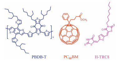
Here, we designed and synthesized a novel AH-D-A-type PJM of H-TRC8. Its structure is shown in Fig. 1. This H-TRC8 consists of an electron-donating (D) center of thiophene, an electron-accepting (A) terminal of octyl-substituted rhodanine, and another hydrogen-donating/electron-accepting terminal (AH) of rhodanine. Considering that H-TRC8 has good compatibility with poly[[4, 8-bis[5-(2-ethylhexyl)-2-thienyl] benzo [1, 2-b:4, 5-b'] dithiophene-2, 6 -diyl] -2, 5-thiophenediyl [5, 7-bis (2-ethylhexyl)-4, 8-dioxo-4H, 8H-benzo[1, 2-c:4, 5c']dithiophene-1, 3-diyl]] (PBDB-T) and PC60BM, in this work, we carried out a series of investigation about the effect of H-TRC8 on photovoltaic property and device stability on the basis of the reported PBDB-T/PC60BM-based OSCs [29, 30]. It is found that, while H-TRC8 is added into the PBDB-T/PC60BM blend film, the resulting blend film exhibits an enhanced absorption and improved morphology. Furthermore, the resulting PBDB-T/PC60BM/H-TRC8 based devices further exhibit a significantly improved PCE of 8.06% at H-TRC8 ratio of 1.25 wt%. This PCE value is increased by 20.6% in comparison with that (6.68%) of the PBDB-T/PC60BM-based device. It is interesting that the device stability is also significantly enhanced at the same time. Our study provides a new strategy to improve PCE and device stability by introducing PJM in photoactive layer.

|
Download:
|
| Fig. 1. Chemical structures of PBDB-T, PC60BM and H-TRC8. | |
The synthetic route of H-TRC8 is shown in Scheme S1 (Supporting information). H-TRC8 was synthesized through condensation reactions. Its structure is characterized with 1H NMR, 13C NMR and LC–MS. Its thermal decomposition temperature of 340 ℃ is observed at 5% weight loss, as measured by thermogravimetric analysis (TGA) under nitrogen atmosphere at a heating rate of 10 ℃/min (Fig. S1a in Supporting information). The melting and crystalline temperatures of H-TRC8 of 154 ℃ and 148 ℃ are respectively observed in the recorded differential scanning calorimetry (DSC) curve during heating and cooling scans (Fig. S1b in Supporting information). It means that H-TRC8 has high thermal stability and a definite crystallinity.
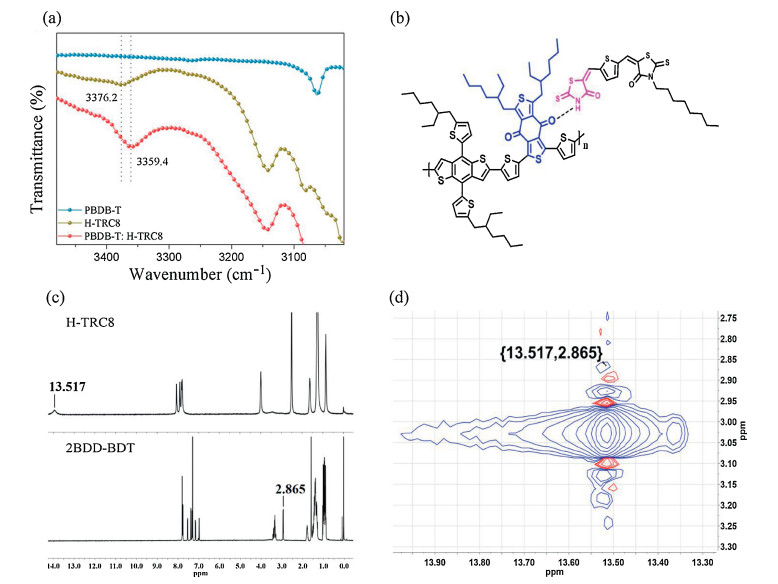
Figs. 2a and b show the FT-IR spectra of the H-TRC8/PBDB-T neat films and the H-TRC8/PBDB-T blend film. The N—H stretching vibration peak of amide group (CONH) is located at 3376.2 cm-1 in the H-TRC8 neat film and 3359.4 cm-1 in the PBDB-T/H-TRC8 blend film. Here, the variational N—H vibration peaks suggest that hydrogen bond interaction is really existed between the amide group in H-TRC8 and the carbonyl group in PBDB-T.

|
Download:
|
| Fig. 2. (a) FT-IR spectra for H-TRC8, PBDB-T and H-TRC8/PBDB-Tat wavelength of 30003500 cm-1; (b) the interaction of PBDB-T and H-TRC8; 1H NMR (c) and 2D 1H NMR spectra (d) of H-TRC8 and 2BDD-BDT. | |
In order to farther verify the presence of intermolecular hydrogen bonds, their 1H NMR spectra are recorded in Fig. 2c. Pure H-TRC8 in dimethyl sulfoxide-d6 and 2BDD-BDT (a fragment of PBDB-T, Fig. S2 in Supporting information) in deuterated chloroform exhibit a sharp peak, respectively. In comparison with the 2D 1H NMR spectrum of the 2BDD-BDT/H-TRC8 blend in dimethyl sulfoxide-d6/deuterated chloroform (v/v, 1:4), shown in Fig. 2d, the corresponding resonances of H signals are observed at 13.52 and 2.86 ppm between H-TRC8 and 2BDD-BDT according to the H/H cross peak. It indicates that the H-bond is surely formed between them. On the other hand, H-TRC8 is slightly soluble, however, the H-TRC8/2BDD-BDT blend film is soluble (Fig. S3 in Supporting information) in chloroform. This result further supports the intermolecular hydrogen bond between H-TRC8 and 2BDD-BDT. In addition, we also measured 1D and 2D 1H NMR spectra of the H-TRC8 and PC60BM blend in dimethyl sulfoxide-d6/deuterated chloroform (v/v, 1:4), recorded in Fig. S4 (Supporting information). The corresponding resonances of H signals are not observed at all chemical shift (ppm) between H-TRC8 and PC60BM according to the H/H cross peaks. It verifies that there is not any hydrogen bond between H-TRC8 and PC60BM.
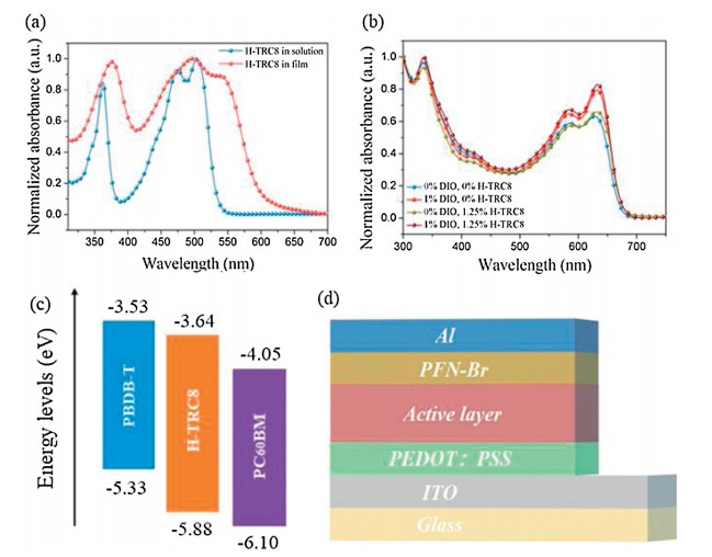
The UV–vis absorption spectrum of H-TRC8 is shown in Fig. 3a. In the chloro-benzene solution (10-5 mol/L), H-TRC8 displays two strong absorption bands at about 350 nm and 475 nm. The molar extinction coefficient (εmax) is 5.37×10⁴ L mol-1 cm-1 at the lowlying absorption peak. In its as-cast neat film, H-TRC8 exhibits a considerably broad and red-shifted absorption profile owing to its effective intermolecular stacking. The optical bandgap is estimated to be 2.08 eV according to its thin-film absorption onset.

|
Download:
|
| Fig. 3. (a) normalized uv–vis absorption spectra of h-trc8. (b) normalized uv–vis absorption spectra of the pbdb-t/pc60bm blend films at different dio and h-trc8 doping [(fig._4)td$fig]contents. (c) energy level diagrams of pbdb-t, pc60bm and h-trc8. (d) the device architecture. | |
The absorption spectra of the PBDB-T/PC60BM blend films are shown in Fig. 3b at different DIO and H-TRC8 doping contents. It is found that the blend film without DIO and H-TRC8 displays the weakest absorption. The blend film with both 1.0 vol% DIO and 1.25 wt% H-TRC8 displays the most intense absorption in comparison to those blend films with only 1.0 vol% DIO or 1.25 wt% H-TRC8. It indicates that an appropriate introduction of H-TRC8 as PJM into the PBDB-T/PC60BM blend film can enhance light harvest under DIO assistance.
The oxidation and reduction curves of H-TRC8 in chloroform solution measured by cyclic voltammetry (CV) method are shown in Fig. S1c (Supporting information). The highest occupied molecular orbit (HOMO) and the lowest unoccupied molecular orbit (LUMO) energy levels (EHOMO/ELUMO) are estimated to be -5.88 eV/-3.64 eV based on empirical equation. Fig. 3c describes the HOMO and LUMO energy levels of PBDB-T, PC60BM, and HTRC8. It is found that H-TRC8 has complementary absorption and appropriate energy levels with the PBDB-T and PC60BM. Therefore, introducing H-TRC8 into the PBDB-T/PC60BM blend film is available to increase photo absorption and carrier transportation/separation for the resulting active layer.
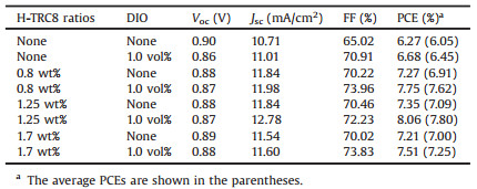
Fig. 3d shows a conventional device configuration of ITO/PEDOT:PSS/active layer/PFN-Br/Al. These devices were carefully made and optimized by varying weight ratios of H-TRC8 and DIO. The current density (J) and voltage (V) characteristics of these devices are shown in Figs. 4a–c. We find that the PBDB-T/PC60BM based device without DIO and H-TRC8 displays the lowest power conversion efficiency (PCE) of 6.27%. And the PBDB-T/PC60BM based device with only 1.0 vol% DIO displays an increasing PCE of 6.68%, which is similar to the previous result reported by Hou et al. [25]. It is interesting that the photovoltaic performances are further remarkably enhanced for the PBDB-T/PC60BM based devices by simultaneously adding 1.0 vol% DIO and appropriate H-TRC8 into the active layer. The device with 1.0 vol% DIO and 1.25 wt% H-TRC8 exhibits the best photovoltaic properties with a PCE of 8.06%, Voc of 0.87 V, Jsc of 12.78 mA/cm2 and FF of 72.23% (Table 1). The PCE value is enhanced by 20.06% in comparison with that in the device at 1.0 vol% DIO. It means that developing PJM is an effective strategy to improve photovoltaic performance for the binary fullerene OSCs.

|
Download:
|
| Fig. 4. (a) The J–V and (b) EQE curves of the PBDB-T/PC60BM OSCs at the best DIO and H-TRC8 ratios. (c) J1/2–V plots of the electron-only devices and (d) hole-only devices based on the PBDB-T/PC60BM blend film at different DIO and H-TRC8 ratios. | |
|
|
Table 1 Photovoltaic parameters of OSCs based on PBDB-T/PC60BM with various H-TRC8 and DIO doping ratios. |
In order to understand why the PBDB-T/PC60BM device exhibits the highest Jsc at 1.0 vol% DIO and 1.25 wt% H-TRC8, the external quantum efficiencies (EQEs) of the PBDB-T/PC60BM blend films were tested and are recorded in Fig. 4b, Figs. S5a and b (Supporting information) at different DIO and H-TRC8 weight ratios. It is found that adding appropriate H-TRC8 into PBDB-T/PC60BM blend films can increase spectral response for the resulting blend films with H-TRC8 weight ratios from 0.8 wt% to 1.7 wt%. Under further mixing with 1.0 vol% DIO, the PBDB-T/PC60BM blend film at 1.25 wt% exhibits the strongest spectral response from 300 nm to 700 nm with an EQE of 77.2% at 620 nm. The stronger spectral response is beneficial for increase in the Jsc value.
The electron mobility (μe) and hole mobility (μh) of the PBDBT/PC60BM blend films with various H-TRC8 and DIO doping ratios were measured by the space-charge-limited current (SCLC) method in their electron-only and hole-only devices, respectively. The device structures are ITO/ZnO/active layer/PFN-Br/Al for the electron -only devices and ITO/PEDOT:PSS/active layer/MoO3/Al for the hole-only devices. Figs. 4g and h show the J1/2–V plots of the electron-only devices and hole-only device, respectively. For the PBDB-T/PC60BM blend film with 1.0 wt% DIO, the calculated μe and μh values are 2.79×10⁻⁴ and 4.63×10⁻⁴ cm2 V-1 s-1, respectively, with a μe/μh ratio of 0.60. In contrast, for the PBDB-T/PC60BM blend film with 1.0 vol% DIO and 1.25 wt% H-TRC8, the calculated μe and μh values are 6.51×10⁻⁴ and 5.69×10⁻⁴ cm2 V-1 s-1, respectively, with a μe/μh ratio of 1.14. It is obvious this blend film with DIO and H-TRC8 exhibits higher carrier mobility and better charge balance than that blend film with only DIO. This means that adding H-TRC8 and DIO is available to make well-organized and compact arrangement for the active layer.
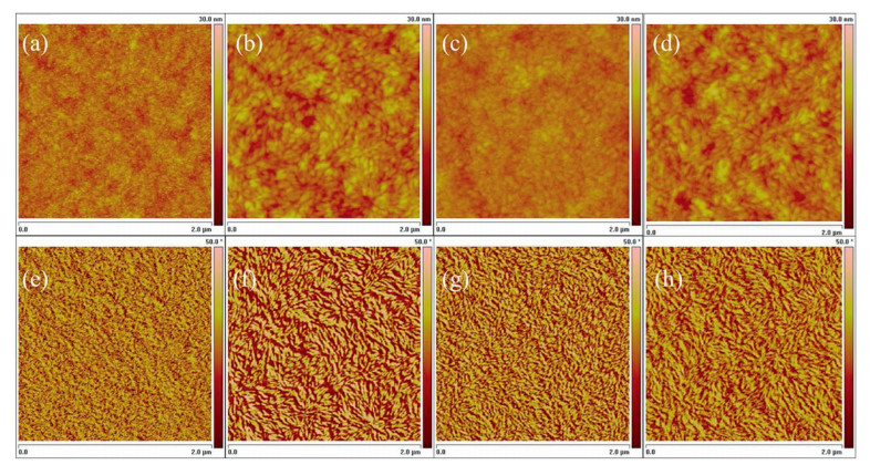
Fig. 5 shows the surface phase separation images of the PBDB-T/PC60BM blend films at different DIO and H-TRC8 ratios, recorded by atomic force microscope (AFM). The root mean square (RMS) roughnesses of 1.73, 2.25, 1.28 and 2.10 nm are obtained in the blend film without DIO and H-TRC8 (blend A), the blend film with 1.0 vol% DIO (blend B), the blend film with 1.25 wt% H-TRC8 (blend C) and the blend film with 1.0 vol% DIO and 1.25% H-TRC8 (blend D), respectively. No large aggregates are observed from all height images, but better homogeneous surfaces are presented in the blend films B and D with an appropriate RMS roughness about 2 nm. In comparison with the phase images of these blend films, it is found that shapes of the domains in the blends A, B, C and D are very different. In the blend A, a few of particles with irregular shape are found in the phase image. However, the fibril-like domains are observed and their topographies are improved after adding DIO or/and H-TRC8 in the blends B, C and D. It is worth mentioning that the blend D exhibits the most suitable phase-separation morphology due to the synergy effect between DIO and H-TRC8, which can improve Jsc and FF, eventually resulting in improvement in their photovoltaic performance.

|
Download:
|
| Fig. 5. AFM height images (a–d) and phase images (e–h) of the PBDB-T/PC60BM blend films at different DIO and H-TRC8: (a, e) no DIO and H-TRC8; (b, f) 1.0 vol% DIO; (c, g) 1.25 wt% H-TRC8; (d, h) 1.0 wt% DIO and 1.25 wt% H-TRC8. | |
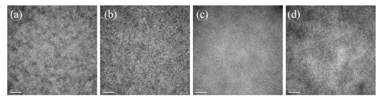
Fig. 6 further shows the morphology of these PBDB-T/PC60BM blend films at different weight ratios of DIO and H-TRC8, recorded by transmission electron microscopy (TEM). It is found that the blend C with H-TRC8 exhibits short fibril domains in comparison with the blend A, which permeate evenly in the whole phase image and is correspond with that in AFM. After adding DIO, the blend D exhibits the most suitable phase-separation structures, which is available to improve Jsc and FF.

|
Download:
|
| Fig. 6. TEM images of the PBDB-T/PC60BM blend films at different DIO and H-TRC8: (a) no DIO and H-TRC8; (b) 1.0 vol% DIO; (c) 1.25 wt% H-TRC8; (d) 1.0 vol% DIO and 1.25 wt% H-TRC8. | |
In the previous studies, solvent additives, such as 1, 8-diiodooctane (DIO) is often used in OSCs to improve PCE, but it seriously reduce the device stability [28]. Once the residual DIO is evaporated from the active layer during the operation process, domain size in OSCs should become smaller. This makes the well-connected domains lose their connection and accelerates morphological degradation process. In order to investigate the effect of H-TRC8 on device stability, the PCEs and J–V characteristics were measured and are shown in Figs. 7 a and b, for the PBDB-T/PC60BM based OCSs at various DIO and HTRC8 doping ratios after heating at 150 ℃ for 120 h. The PCE values of the device A without any additives, the device B with 1.0 vol% DIO, the device C with 1.25 wt% H-TRC8 and the device D with 1.0 vol% DIO and 1.25 wt% H-TRC8 decay 65%, 77%, 43% and 62% in comparison with their original values, respectively. As shown in Figs. 7c and d, the variation tendency of EQE is similar to that of PCE. It indicates that introduction of H-TRC8 into the PBDB-T/PC60BM active layer is available to efficiently suppress PCE roll-off and increase device stability. We consider that shrinkage of the PBDB-T domains should become difficult owing to the effect of H-bonds between H-TRC8 and PBDB-T in the devices. As a result, the PBDB-T/PC60BM OSCs with H-TRC8 have better device stability.

|
Download:
|
| Fig. 7. Thermal stability of OSCs based devices A, B, C and D. (a) The change of PCE heating at 150 ℃ for 120 h; J–V (b) and EQE (c and d) curves after heating at 150 ℃ for 120 h. | |
In summary, we developed a novel PJM of H-TRC8 with rhodanine unit. While 1.25 wt% H-TRC8 and 1.0 vol% DIO are added into the PBDB-T/PC60BM blend films, themorphology of active layer is improved. And its BHJ OSCs display an increased PCE value of 8.06%, which is increased by 20% in comparison with that of PBDBT/PC60BM-based devices (6.68%). Furthermore, this device exhibits an increasing device stability at 150 ℃ for 120 h. Our results indicate that PCE value and device stability can be improved by appropriate introduction of H-TRC8 into the active layer of PBDB-T/PC60BM. H-TRC8 as a PJM should become a promising photovoltaic material to realize high-performance OSCs with high PCE and device stability.
Declaration of competing interestThe authors declare that there are no conflicts of interest.
AcknowledgmentsWe acknowledge the financial support from the National Natural Science Foundation of China (Nos. 51673031, 51573154), the Major Program of the Natural Science Research of Jiangsu Higher Education Institutions (No. 18KJA480001), the Top-Notch Academic Programs Project (TAPP) for Polymeric Materials Science and Technology & the Priority Academic Program Development (PAPD) of Jiangsu Higher Education Institutions, Jiangsu Provincial Talents Project of High-Level Innovation and Entrepreneurship, and the Talent Project of Jiangsu Specially-Appointed Professor.
Appendix A. Supplementary dataSupplementary material related to this article can be found, in the online version, at doi:https://doi.org/10.1016/j.cclet.2020.03.036.
| [1] |
X. Che, Y. Li, Y. Qu, S.R. Forrest, Nat. Energy 3 (2018) 422-427. DOI:10.1038/s41560-018-0134-z |
| [2] |
G. Huang, J. Zhang, N. Uranbileg, et al., Adv. Energy Mater. 8 (2018) 1702489. DOI:10.1002/aenm.201702489 |
| [3] |
Y. Lin, J. Wang, Z.G. Zhang, et al., Adv. Mater. 27 (2015) 1170-1174. DOI:10.1002/adma.201404317 |
| [4] |
J. Wang, J. Zhang, Y. Xiao, et al., J. Am. Chem. Soc. 140 (2018) 9140-9147. DOI:10.1021/jacs.8b04027 |
| [5] |
B. Fan, D. Zhang, M. Li, et al., Sci. China Chem. 62 (2019) 746-752. DOI:10.1007/s11426-019-9457-5 |
| [6] |
Z. Zheng, Q. Hu, S. Zhang, et al., Adv. Mater. 34 (2018) 1801801. |
| [7] |
L. Meng, Y. Zhang, X. Wan, et al., Science 361 (2018) 1094-1098. DOI:10.1126/science.aat2612 |
| [8] |
J. Yuan, Y. Zhang, L. Zhou, et al., Joule 3 (2019) 1140-1151. DOI:10.1016/j.joule.2019.01.004 |
| [9] |
H. Tan, X. Zheng, J. Zhu, J. Yu, W. Zhu, J. Mater. Chem. C 7 (2019) 13301-13306. DOI:10.1039/C9TC04898G |
| [10] |
H. Tan, H. Tan, X. Zheng, et al., J. Mater. Chem. C 8 (2020) 3183-3191. DOI:10.1039/C9TC06594F |
| [11] |
W. Peng, G. Zhang, L. Shao, et al., J. Mater. Chem. A 6 (2018) 24267-24276. DOI:10.1039/C8TA09370A |
| [12] |
W. Peng, G. Zhang, M. Zhu, et al., ACS Appl. Mater. Interfaces 11 (2019) 48128-48133. DOI:10.1021/acsami.9b16686 |
| [13] |
Q. Liu, Y. Jiang, K. Jin, et al., Sci. Bull. 65 (2020) 272-275. DOI:10.1016/j.scib.2020.01.001 |
| [14] |
W. Song, X. Fan, B. Xu, et al., Adv. Mater. 30 (2018) 1800075. DOI:10.1002/adma.201800075 |
| [15] |
J. Yu, Y. Xi, C.C. Chueh, et al., Nano Energy 39 (2017) 454-460. DOI:10.1016/j.nanoen.2017.07.031 |
| [16] |
Y.C. Chao, C.H. Chuang, H.L. Hsu, et al., Sol. Energy Mater. Sol. Cells 157 (2016) 666-675. DOI:10.1016/j.solmat.2016.07.041 |
| [17] |
C.G. Wu, C.H. Chiang, H.C. Han, J. Mater. Chem. A 2 (2014) 5295-5303. DOI:10.1039/C3TA15378A |
| [18] |
B.M. Schulze, N.T. Shewmon, J. Zhang, et al., J. Mater. Chem. A 2 (2014) 1541-1549. DOI:10.1039/C3TA13529B |
| [19] |
P. Cheng, C. Yan, T.K. Lau, et al., Adv. Mater. 28 (2016) 5822-5829. DOI:10.1002/adma.201600426 |
| [20] |
X. Kong, H. Lin, X. Du, et al., J. Mater. Chem. C 6 (2018) 9691-9702. |
| [21] |
X. Li, X. Du, H. Lin, et al., ACS Appl. Mater. Interfaces 11 (2019) 15598-15606. DOI:10.1021/acsami.9b02121 |
| [22] |
X. Du, X. Lu, J. Zhao, et al., Adv. Funct. Mater. 29 (2019) 1902078. DOI:10.1002/adfm.201902078 |
| [23] |
C. Zhang, T. Heumueller, S. Leon, et al., Energy Environ. Sci. 12 (2019) 1078-1087. DOI:10.1039/C8EE03780A |
| [24] |
Q. Lin, X.W. Guan, S.S. Song, et al., Polym. Chem. 10 (2019) 253-259. DOI:10.1039/C8PY01299G |
| [25] |
Z. Xiao, T. Duan, H. Chen, K. Sun, S. Lu, Sol. Energy Mater. Sol. Cells 182 (2018) 1-13. DOI:10.1016/j.solmat.2018.03.013 |
| [26] |
G. Sai-Anand, A. Dubey, A.I. Gopalan, et al., Sol. Energy Mater. Sol. Cells 182 (2018) 246-254. DOI:10.1016/j.solmat.2018.03.031 |
| [27] |
W. Kim, J.K. Kim, E. Kim, et al., J. Phys. Chem. C 119 (2015) 5954-5961. DOI:10.1021/jp510996w |
| [28] |
D. Yang, F.C. Löhrer, V. Körstgens, et al., ACS Energy Lett. 4 (2019) 464-470. DOI:10.1021/acsenergylett.8b02311 |
| [29] |
D. Qian, L. Ye, M. Zhang, et al., Macromolecules 45 (2012) 9611-9617. DOI:10.1021/ma301900h |
| [30] |
W. Zhao, L. Ye, S. Zhang, M. Sun, J. Hou, J. Mater. Chem. A 3 (2015) 12723-12729. DOI:10.1039/C4TA07029A |