 2020, Vol. 31


b Center of Materials Science and Optoelectronics Engineering, University of Chinese Academy of Sciences, Beijing 100049, China;
c School of Physical Science and Technology, Lanzhou University, Lanzhou 730000, China;
d Dalian National Laboratory for Clean Energy, Chinese Academy of Sciences, Dalian 116023, China
Lithium-ion batteries (LIBs), as the most popular electrochemical energy storage devices, are widely commercialized in modern electronic products. Nevertheless, the production of 1 kW h LIBs emits up to 75 kg of carbon dioxide into the environment, resulting in serious environmental issue [1, 2]. Also, the uneven distribution and high price of lithium resources also restrict the sustainable development of LIBs. Therefore, in order to build a low-carbon society and to ensure larger applications of rechargeable batteries in the future, there is an urgent need to develop cleaner and cheaper energy storage devices. Recently, aqueous zinc-based batteries have been considered to be a competitive candidate to replace LIBs because of their intrinsic characteristics of high safety, low toxicity, low cost and multi-valent ion storage [3-10]. As shown in Table S1 (Supporting Information), metal Zn is more electrochemically stable than lithium and sodium, and has a low redox potential (-0.763 V vs. standard hydrogen electrode), which is suitable for using high-safety and low-cost aqueous electrolytes [11-13]. More importantly, the Zn anode can provide a very high theoretical mass specific capacity (820 mAh/g), which is much higher than that of the graphite anode (372 mAh/g) used in the LIBs [14, 15]. In addition, the Zn anode is geographically abundant in reserves when compared with Li and Na [16, 17]. Thus, more and more researchers have been devoting themselves to designing various aqueous Zn-based batteries, and significant research progress has been achieved in the related fields [18-20].
Because zinc is directly used as the anode in Zn-based batteries, the cathode materials directly determine the performance of the devices. Nowadays, the development direction of the cathode materials is to achieve a higher specific capacity, and the reported cathode materials are usually vanadium-based materials, manganese-based materials and Prussian blue analogs [4, 21-27]. Taking the representative cathodes as examples for comparison, the LixV2O5·nH2O material showed a high capacity and good rate performance [26], the polyaniline-intercalated MnO2 showed long cycling stability [25-27], and the Prussian blue analogs showed a relative high operation voltage [28-30]. However, the overall performance of Zn-based batteries using these cathodes was still unsatisfied. Therefore, exploiting more suitable cathode materials is of importance for constructing better Zn-based batteries.
In electrochemical energy storage, multiple transition metal oxides as cathode can generally provide a wider electrochemical stability window and a higher capacity compared with single metal oxides cathode [19]. For instance, it has been reported that MnCoOx [31] and FeCoOx [32] multi-metal oxides could provide wider electrochemical windows and higher reversible specific capacities in LIBs. The multielement metals play important roles in the cathodes: Mn can facilitate the interface mass transfer and thus enhances the thermodynamic property [33, 34], Co can increase the specific capacity [35, 36], and Fe is in favor of the structural stability and the rate performance [37, 38]. However, the poor electrical conductivity of transition metal oxides is the biggest defect, restricting their rapid application in rechargeable batteries.
In this work, a new type of ternary metal oxide-graphene composite material, i.e., MnFe2Co3O8 nanodots decorated on functional graphene sheets (MnFe2Co3O8 NDs/FGS) is designed and used as cathode for aqueous hybrid zinc energy storage. Coupling with an aqueous zinc sulfate-potassium hydroxide hybrid electrolyte, the resulting battery exhibited a wide electrochemical window of 0.1~1.8 V and a high specific capacity of 660 mAh/g at a current density of 0.1 A/g. After cycling 1000 cycles at a high current density of 5 A/g, the capacity retention was still higher than 82%. The battery delivered an ultrahigh energy density of 1135 Wh/ kg and a scalable power density of 5754 W/kg (calculated based on the cathode). Density functional theory (DFT) calculation results revealed that the cathode possesses good structural stability benefitted from the valence charge density distribution in MnFe2Co3O8 NDs. Moreover, such MnFe2Co3O8 NDs/FGS cathode also exhibited high electrocatalytic activity for oxygen evolution reaction and thus could be used for constructing a Zn-air battery with an ultrahigh reversible capacity of 9556 mAh/g. This work may provide valuable contributions for designing related high-performance Zn batteries toward large-scale practical applications.
Graphite powder was used to prepare graphene oxide (GO) by a modified Hummers' method [39, 40]. 20 mg GO was added to 20 mL N, N-dimethyl formamide (DMF) and sonicated for 2 h. Then, 10 mg Mn2(CO)10 and 10 mg Co2(CO)8 were dispersed in 10 mL DMF solution. And, 0.25 g Fe(CO)5 was dissolved in 50 mL DMF. 2 mL of this Fe(CO)5 solution was added to the above Mn2(CO)10-Co2(CO)8 solution, and 0.4 mL octylamine was dripped into the mixed solution. The resulting solution was added to the GO dispersion. Finally, the mixed suspension was transferred to Teflon-lined stainless-steel autoclave and heated at 170 ℃ for 2 h. After cooled down, the solid product was centrifuged, washed with anhydrous ethanol and deionized water, and freeze-dried. To remove residual octylamine entirely and reduce GO, the product was annealed at 400 ℃ for 2 h in Ar atmosphere, and the MnFe2Co3O8 NDs/FGS material was obtained.
Transmission electron microscope (TEM, JEOL 2100 FEG), high-resolutiono TEM (HRTEM) and atomic force microscope (AFM, MultiMode 8) were employed to observe the morphology and structure of MnFe2Co3O8 NDs/FGS. The phase composition and sturcture of the sample were characterization by X-ray diffraction (XRD) (Rigaku D/Max-2400, Cu-Ka radiation, λ = 0.15405 nm). X-ray photoelectron spectroscopy technology (XPS, ESCALAB 250x) was employed to detect the chemical valence of the surface elements.
Oxygen evolution reaction (OER) test [41, 42]: Catalyst solution was prepared by dispersing 5 mg active material in 2 mL deionized water, 500μL isopropanol and 50μL Nafion. Then remove 30 μL of the mixture solution and placed it on glassy carbon electrode. The OER tests were performed in the three-electrode system under linear sweep voltammetry (LSV) with a scan rate of 5 mV/s and a voltage window of 0–1.8 V. The glassy carbon electrode was used as the working electrode, the saturated calomel electrode as the reference electrode, and a platinum electrode as the counter electrode. In order to remove the oxygen of the electrolyte, we used high purity nitrogen inlet to the electrolyte with 8 h, and then, we conducted the linear sweep voltammetry (LSV) characterization with the nitrogen. Also, we have measured the dissolved oxygen content by the dissolved oxygen instrument (DOS-808 A). The dissolved oxygen content of the electrolyte with air was 6 mg/L, and the dissolved oxygen content of the electrolyte with oxygen was 9 mg/L. When using the high purity nitrogen inlet to the electrolyte to remove the oxygen, the dissolved oxygen content of the electrolyte was less than 0.10 mg/L.
Each cathode was composed of MnFe2Co3O8 NDs/FGS powder (80 wt%), conductive graphite (10 wt%) and carboxymethylcellulose (CMC) (10 wt%). The active mass loading for the cathode material was about 1 mg/cm2 on the stainless-steel grid current collector. The anode electrode was Zn plates of 1 × 1 cm2. Each battery was assembled into a coin cell with a glass fiber as the separator. Specifically, coin cells were assembled in an open laboratory atmosphere (dissolved O2 content was around 6.24 mg/ L).
The Vienna ab initio Calculation Software Package (VASP) [44, 43] to perform firat-principles calculations in which spin polarization was taken into account. The projector-augmented wave (PAW) [44] method was used to describe the interaction between the valence electrons and ion core. The exchange and correlation terms were determined using the Generalized Gradient Approximation (GGA) in the form proposed by Perdew, Burke and Ernzerhof (PBE) [45]. To ensure all atoms were fully relaxed, the geometry optimization was carried out by using the conjugate gradient algorithm, and the cut-off energy for the plane wave basis was set as 500 eV, and the ionic relaxtion stopped if all the forces was less than 0.01 eV/Å.
A novel synthesis method was used to synthesize the ternary MnFe2Co3O8 NDs/FGS composite. This synthetic method is based on the following reactions:

|

|
where M is Mn or Fe or Co. We used the carbonyl metal (Mn2(CO)10, Fe(CO)5 and Co2(CO)8) as precursor and the carbonyl metal precursors would de-carbonylation at the atomic order of magnitude at relatively low temperature [46-48]. Through controlling the heating threshold temperature, the nanoparticles could evenly distribute on FGS with very small sizes. Specifically, when the carbonyl metals dispersed into the graphene oxide (GO) and surfactant mixture solution, the positive charged octylamine surfactant was in favor of the electrostatic binding between carbonyl metal compounds and GO. When heated to the threshold temperature, MnFe2Co3O8 NDs would bond tightly with GO in the form of covalent bond. Meanwhile, GO was reduced and N-doping by the decompose of N, N-dimethyl formamide (DMF) solvents and formed functional graphene sheets. Thus, this method is simple, controllable and economical to synthesize multiple metal nanoparticles on graphene in large scales.
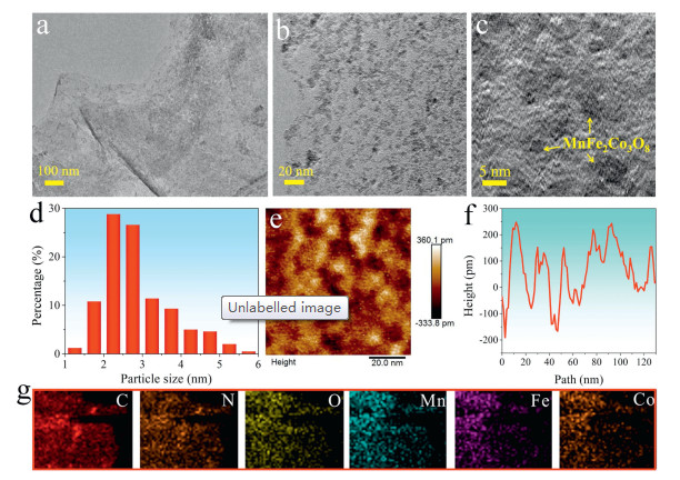
Transmission electron microscopy (TEM) characterization of MnFe2Co3O8 NDs/FGS showed a thin layer morphology with plenty of tiny MnFe2Co3O8 NDs uniformly anchored on graphene sheets and there was no obvious agglomeration on the sheets (Figs. 1a and b). High-resolution TEM (HRTEM) image further showed that the NDs were distributed uniformly (Fig. 1c and Fig. S1 in Supporting information). The statistical size distribution of MnFe2Co3O8 NDs was 2.34 nm (Fig. 1d). The 2D atomic force microscope (AFM) characterization of MnFe2Co3O8 NDs/FGS composite showed the evenly distributed nanoparticles on a single FGS (Fig. 1e and Fig. S2 in Supporting information). These particles exhibited a height of less than 1 nm from the corresponding section height curve, illustrating their flat structure (Fig. 1f). Energy dispersive spectroscopy (EDS) mapping images of MnFe2Co3O8 NDs/FGS revealed the uniform distribution of Mn, Fe, Co, O and N elements on an individual FGS sheet (Fig. 1g).

|
Download:
|
| Fig. 1. Morphological characterization of MnFe2Co3O8 NDs/FGS: (a, b) TEM images with different magnifications (scale bar: 100 and 20 nm, respectively). (c) High-resolution TEM (HRTEM) image (scale bar: 5 nm). (d) The statistical size distribution of MnFe2Co3O8 NDs using nano-measurer software. (e) AFM image with a scale bar of 20 nm and (f) the corresponding section height curve. (g) EDS elements mapping images. | |
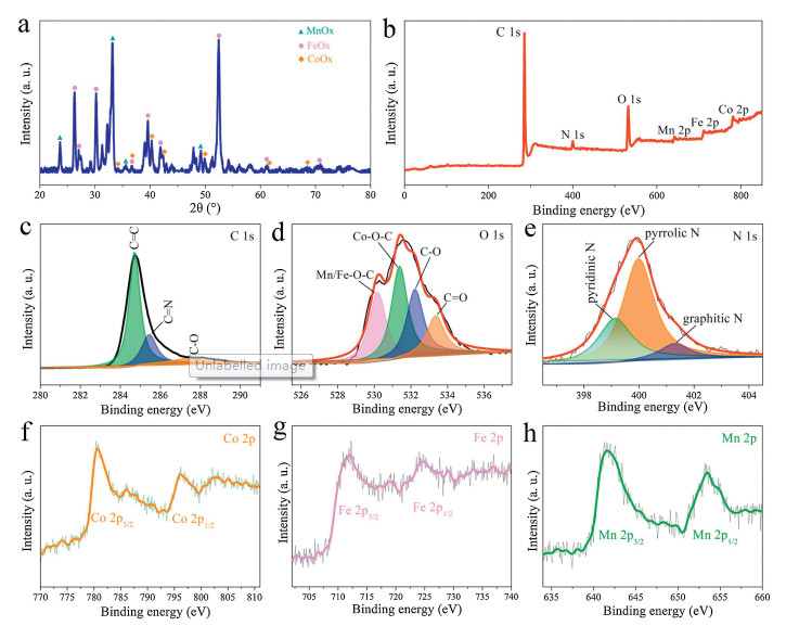
The XRD pattern of MnFe2Co3O8 NDs/FGS exhibited MnOx, FeOx and CoOx peaks as shown in Fig. 2a, indicating the successful synthesis of ternary Mn-Fe-Co metal oxide material. As for the survey XPS spectrum in Fig. 2b, three elements of Mn, Fe and Co showed distinct peaks, and the atomic ratio of Co:Fe:Mn was 3:2:1 (Table S2 in Supporting information). This result was consistent with the characterization of element analysis by inductively coupled plasma (ICP) (Table S3 in Supporting information). It was because the loading amount of metal element is related to the surface energy of the metal atom on the graphene surface, and according to the literature, the binding energy of metal atoms on the surface of graphene is Co > Fe > Mn [49]. At the same time, the C 1s, O 1s and N 1s spectra are shown in Figs. 2c-e. The fitting of C 1s showed that the sub-peaks at 284.7, 285.4 and 287.4 eV were ascribed to C=C, C=N and C-O (Fig. 2c) [50]. As shown in Fig. 2d, the fitted O 1s peaks at 530.1, 531.4, 532.2 and 533.3 eV were ascribed to Mn/Fe-O-C, Co-O-C, C-O and C=O. The fitting peaks of N 1s at 399.1, 399.9 and 401.3 eV were corresponded to pyridinic N, pyrrolic N and graphitic N (Fig. 2e) [51, 52], and the corresponding content percentages were 28.71%, 63.04% and 8.24%, respectively (Table S4 in Supporting information). Besides, the nitrogen content in the MnFe2Co3O8 NDs/FGS composite material measured by XPS was 3.63%. The nitrogen doping could improve the overall electrical conductivity in the composite [53, 54]. Moreover, the existents of pyrrolic N and pyridinic N could provide more diffusion channels and actives sites with additional defect sites [55]. High-resolution XPS spectra of Co 2p, Fe 2p and Mn 2p were shown in Figs. 2f-h. Co 2p3/2 and Co 2p1/2 were ascribed to the binding energy of 780.3 and 796.1 eV (Fig. 2f). Fe 2p3/2 and Fe 2p1/2 were ascribed to the binding energy of 712.1 and 724.4 eV (Fig. 2g) [56, 57]. Mn 2p3/2 and Mn 2p1/2 were ascribed to the binding energy of 641.8 and 653.2 eV (Fig. 2h) [58, 59]. Based on the above analyses, it is clear that Mn, Fe and Co elements co-exist in NDs with the radio of 1:2:3, and them would synergy effects on the MnFe2Co3O8 NDs/FGS cathode for Zn charge storage.

|
Download:
|
| Fig. 2. Structural characterization of MnFe2Co3O8 NDs/FGS: (a) XRD pattern. (b) XPS survey spectrum. (c) C 1s, (d) N 1s and (e) O 1s core-level XPS spectra. High-resolution spectra of (f) Co 2p, (g) Fe 2p and (h) Mn 2p. | |
The electrochemical properties of hybrid Zn battery were investigated using metallic zinc as anode and MnFe2Co3O8 NDs/ FGS as cathode. Firstly, in order to find a proper electrolyte where the cell can show a wider electrochemical stability window and a higher capacity, we tested the electrochemical performance in different electrolytes. When tested in 1 mol/L KOH electrolyte with the set voltage window of 0–1.8 V, the cell cannot did not work properly (Fig. S3a in Supporting information). The galvanostatic cycling performance at 1 A/g with the voltage range of 0–1.8 V in 1 mol/L KOH and 0.1 mol/L KOH were shown in Figs S3b and c (Supporting Information). When tested in 0.9 mol/L ZnSO4 electrolyte, the corresponding battery exhibited good cycling performance (Fig. S4 in Supporting information). Thus, combined with the above two kinds of electrolytes, we tested the electrochemical performance with different volume ratios between ZnSO4 and KOH (Figs. S5 and S6 in Supporting information). It is clear seen that, when the volume ratio of ZnSO4 and KOH was 9:1 (0.9 mol/L ZnSO4 and 0.1 mol/L KOH), the battery showed the best combination of cycling performance and capacity value. Thus, the ZnSO4-KOH hybrid electrolyte with the ratio (9:1) was set for the following studies.
As shown in Fig. 3a, cyclic voltammetry (CV) curve of the MnFe2Co3O8 NDs/FGS electrode at 0.5 mV/s in the voltage range of 0.1–1.8 V vs. Zn2+/Zn exhibited three pairs of redox peaks located at 0.73/0.41 V, 1.14/0.83 V and 1.36/1.18 V, respectively. It suggested a multistep (de)intercalation of Zn2+ during charging and discharging processes. Due to these multistep electrochemical processes, the low threshold voltage could extend to 0.1 V. Fig. 3b shows the typical galvanostatic charge-discharge (GCD) curves, and the discharge specific capacity was 440 mAh/g at 1 A/g. There were three charge/discharge platforms, which were attributed to the multistep electrochemical processes of MnFe2Co3O8. As shown in Fig. 3c, the specific capacity maintained 360 mAh/g (71.1%) at 0.5 A/ g after 60 cycles. And the long cycling performance is shown in Fig. S7 (Supporting information). The tardily capacity decrease was due to the partially irreversible (de)intercalation process resulted from the incomplete release of inserted Zn2+ from the lattice of electrode. In addition, the cycling performance at 1 A/g in 1 mol/L K2SO4 electrolyte is shown in Fig. S8 (Supporting information). The very low capacity demonstrated that the capacity contribution from pure K+ ions was much less than that from Zn2+ ions. In order to clarify the hybrid electrolyte was not affect the Zn anode, we have provided some digital photos of Zn anode after cycling in the hybrid electrolyte. As shown in Figs. S9a and b (Supporting information), the surface of Zn anode was affected by the precipitation in the ZnSO4-KOH hybrid electrolyte. After galvanostatic cycling, there was Zn dendritic on the surface by scanning electron microscope (SEM) characterization.

|
Download:
|
| Fig. 3. Electrochemical performance of the hybrid Zn battery with cathode of MnFe2Co3O8 NDs/FGS: (a) Representative CV curve at 0.5 mV/s in the voltage range of 0.1-1.8 V vs. Zn2+/Zn. (b) GCD curves and (c) galvanostatic cycling performance at 0.5 A/g. (d) Rate capacities at current densities from 0.1 A/g to 10 A/g, and (e) the corresponding GCD curves. (f) Galvanostatic cycling performance at 1 A/g. Long galvanostatic cycling performance at (g) 2 A/g and (h) 5 A/g. | |
Rate capability at current densities from 0.1 A/g to 10 A/g and the corresponding GCD curves are shown in Figs. 3d and e, separately. The MnFe2Co3O8 NDs/FGS showed good rate capability with average discharge capacities of 660, 582, 506, 460, 357, 231 and 113 mAh/g at the current densities of 0.1, 0.2, 0.5, 1, 2, 5 and 10 A/g, respectively. Moreover, after cycling for 60 cycles at 1 A/g, the specific capacity remained 250 mAh/g (56.8% retention, Fig. 3f). At larger current density of 2 and 5 A/g, the specific capacity still remained 228 mAh/g (67.5%) and 112 mAh/g (82.3%) after cycling for 1000 cycles (Figs. 3g and h). The Ragone plots of this cell and the representative reported devices are shown in Fig. S10 (Supporting information). Compared with the reported cathodes in aqueous ZIBs, such as LixV2O5·nH2O [26], H2V3O8 [60], Zn/NVO [61], Zn0.25V2O5·nH2O [62], Na2V6O16·1.63H2O [63] and Na0.33V2O5 [64], the MnFe2Co3O8 NDs/FGS cathode demonstrated the highest energy density (1135 Wh/kg) and an outstanding power density (5754 W/kg) based on the mass of cathode only.
We analyzed the proportion of theoretical capacity contribution in MnFe2Co3O8 NDs/FGS cathode by analyzing the final product (see the calculation in Supporting information). There were four kinds of products formed after Zn insertion: ZnMn2O4 or ZnMnO3, ZnFe2O4, ZnCO2O4 [65-68]. The calculated specific capacity contribution based on the atom ratio of Mn:Fe:Co (1:2:3) is shown in Fig. S11 (Supporting information). In the case where the final compounds with Zn were ZnMn2O4, ZnFe2O4 and ZnCO2O4, the calculated contribution of specific capacity was 482 ×1 (17.4%), 473 × 2 (34.1%) and 449 × 3 (48.5%), as shown in Fig. S11a. In the case where the final compounds were ZnMnO3, ZnFe2O4 and ZnCO2O4, the calculated contribution of specific capacity was 974 ×1 (45.9%), 473 ×1 (22.3%) and 449 ×1.5 (31.8%), as shown in Fig. S11b. From the above analysis, we can recognize the capacity contribution of the ternary metal oxide cathode.
Density functional theory (DFT) calculation was employed to reveal the charge theory and energy storage behavior of the ternary metal oxide cathode in the Zn-based battery. Fig. 4 shows the four possible configurations and the corresponding valence charge density distribution diagrams of the compounds combined with Zn were Mn2ZnO4, MnZnO3, Zn(FeO2)2 and Zn(CoO2)2, respectively. Also, the optimized configurations are shown in Fig. S12 (Supporting information), and the calculated net charges are shown in Table S5 (Supporting information). The net charges order in MnFe2Co3O8 was Mn > Fe > Co, which corresponded to the order of magnitude of electronegativity. When comparing the compounds of Mn2ZnO4, Zn(FeO2)2 and Zn(CoO2)2, this sequence was affected by the charge of O atom, and the absolute charge value of the O atom was also decreased. At the same time, the charge of Zn increased gradually. This was because O got less electrons from Mn/Fe/Co (denoted as M) and got more electrons from Zn. The charge of M varied more than that of Zn, and the absolute value of charge of M and O went down. Thus, the electrovalent bond intensity was in turn down from the sequence of Mn2ZnO4, Zn(FeO2)2, Zn(CoO2)2.

|
Download:
|
| Fig. 4. Density functional theory (DFT) calculation of possible four configurations and the corresponding valence charge density distribution diagrams of the compounds with Zn: (a) Mn2ZnO4, (b) MnZnO3, (c) Zn(FeO2)2 and (d) Zn(CoO2)2. | |
The calculated covalent bond lengths are shown in Table S6 (Supporting information). It is distinctly that the covalent bond of M–O was larger than Zn-O. The valence electron structure of M was 3d5~74s2 and the number of valence electrons was more than half the number of valence orbitals. From the sequence of MnZnO3, Mn2ZnO4, Zn(FeO2)2, Zn(CoO2)2, the charge number of M decreased gradually and the number of electrons on M increased. Thus, from the configurations of MnZnO3 to Zn(CoO2)2, when the M interacted with O, the electrons on M would fill in the antibonding orbital (including changes in charge and atomic number). Thus, the sequence of covalent bond order of M–O decreased gradually. Meanwhile, from MnZnO3 to Zn(CoO2)2, the charge of Zn gradually increased. In other words, the number of bonding electrons on Zn decreased gradually, so the covalent bond order of Zn-O decreased gradually. The valence electron structure of Zn was 3d104s2, and the number of valence electrons was less than half the number of valence orbitals in Zn. For comparison, the valence electron structure of O was 2s22p4, and the number of valence electrons was more than half the number of valence orbitals in O. Therefore, from MnZnO3 to Zn(CoO2)2, Zn charge increased gradually, while the absolute value of O negative charge decreased. When the Zn interacted with O, the reduction of antibonding electrons was the dominant effect. In this way, the sequence of Zn-O covalent bond increased gradually, and the change of the covalent bond sequence of M–O was significantly greater than that of Zn-O. However, the strength of M–O and Zn-O covalent bonds both decreased gradually. Thus, the covalent bond strength was a downward trend. Finally, from MnZnO3 to Zn(CoO2)2, the conductivity should also increase gradually. DFT calculation results revealed that the cathode possesses good structural stability benefitted from the valence charge density distribution in MnFe2Co3O8 NDs.
To highlight the utility of MnFe2Co3O8 NDs/FGS on electrocatalytic activity, oxygen evolution reaction (OER) tests were conducted in 0.1 mol/L KOH at 5 mV/s under the three-electrode system. As shown in Fig. 5a, MnFe2Co3O8 NDs/FGS exhibited a smaller overpotential at 5 mA/cm2 with oxygen than that with nitrogen. Linear sweep voltammetry (LSV) characterization indicated that the high OER catalytic activity of the MnFe2Co3O8 NDs/FGS both with oxygen as well as with air. The Tafel slopes, as shown in Fig. 5b, were analyzed to study the OER catalytic kinetics of MnFe2Co3O8 NDs/FGS. It exhibited Tafel slope of 105 mV/dec with oxygen and 178 mV/dec with air, both were lower than that with nitrogen (637 mV/dec), suggesting better OER kinetics of the MnFe2Co3O8 NDs/FGS. Thus, the MnFe2Co3O8 NDs/FGS could be used as the cathode in aqueous Zn-air batteries (using 6 mol/L KOH electrolyte here).

|
Download:
|
| Fig. 5. Electrochemical performance of the Zn-air battery using MnFe2Co3O8 NDs/FGS as cathode. (a) Oxygen evolution reaction (OER) tests of MnFe2Co3O8 NDs/FGS in 0.1 mol/L KOH with a scan rate of 5 mV/s with different atmosphere. (b) Tafel plots of MnFe2Co3O8 NDs/FGS. (c) Open circuit potential of the Zn-air battery with standing time of 3 h. (d) Terminal voltage of charge. (e) Charge and discharge curves at 0.5 mA/cm2. (f) Full discharge curve at 0.5 mA/cm2, i.e., voltage (vs. Zn) as a function of specific capacity. (g) Charge and discharge curves with a threshold value of 1000 mAh/g at current density of 0.5 mA/cm2. | |
Firstly, we used carbon paper as current collector and its back was added with a liquid permeable film. Thus, the inlet oxygen could contact with the active material MnFe2Co3O8 NDs/FGS. After standing for 3 h, the open circuit potential of the Zn-air battery was 1.42 V (Fig. 5c). After discharging for 17 h, the terminal voltage of the battery was around 1.1 V (Fig. 5d). The stable discharge voltage reflected continuous catalysis of the active material in the presence of oxygen. Fig. 5e shows the charge and discharge curves of the Zn-air battery at current density of 0.5 mA/cm2. The full discharge curve at current density of 0.5 mA/cm2 showed a high specific capacity (Fig. 5f), which reached to 9556 mAh/g. When the threshold capacity value was set to 1000 mAh/g, the charge and discharge curves at 0.5 mA/cm2 are shown in Fig. 5g. It can been seen that the MnFe2Co3O8 NDs/FGS material could work well in Zn-air battery and delivered a high reversible capacity.
Based on the results from ZIBs and Zinc-air battery we built, we can conclude that the good combination of the Zn anode and the MnFe2Co3O8 NDs/FGS cathode in hybrid aqueous electrolytes could present highly reversible Zn-based electrochemistry (Table S7 in Supporting information), that is both environmentally benign and safe. Of course, it should be mentioned that, for practical applications, the electrochemical reactions and stability need to be carefully evaluated. In particular, the reactions between the cathode, anode and electrolyte need to be carefully controlled and optimized.
In summary, a new type of cathode material MnFe2Co3O8 NDs/ FGS has been designed and used as promising cathode for aqueous hybrid Zn-based energy storage. Coupling with the ZnSO4-KOH hybrid electrolyte, the as-built battery was able to stably work from 0.1 V to 1.8 V, showed a high specific capacity of 660 mAh/g at a current density of 0.1 A/g, delivered an ultrahigh energy density of 1135 Wh/kg and a scalable power density of 5754 W/kg (calculated based on the cathode) and exhibited a long cyclic life of 1000 cycles at 5 A/g. The reasonable valence charge density distribution in MnFe2Co3O8 NDs, good structural strength as well as high conductivity of the cathode, and right electrolyte choice resulted in the outstanding overall performance. Additionally, we have aslo demenstrated that such MnFe2Co3O8 NDs/FGS exhibited high electrocatalytic activity for oxygen evolution reaction and thus could be used for constructing a Zn-air battery with an ultrahigh reversible capacity of 9556 mAh/g. This present work therefore provides an encouraging cathode material towards constructing safe Zn-based batteries with high performance.
Declaration of competing interestThe authors declare no conflicts of interests.
AcknowledgmentsThis work was supported by the National Nature Science Foundations of China (Nos. 21673263 and 21805292), One-ThreeFive Strategic Planning of Chinese Academy of Sciences (CAS) and the DNL Cooperation Fund, CAS (No. DNL180307).
Appendix A. Supplementary dataSupplementary material related to this article can be found, in the online version, at doi:https://doi.org/10.1016/j.cclet.2020.03.014.
| [1] |
D. Larcher, J.M. Tarascon, Nat. Chem. 7 (2015) 19-29. DOI:10.1038/nchem.2085 |
| [2] |
J.M. Tarascon, M. Armand, World Scientific (2011) 171-179. |
| [3] |
H. Pan, Y. Shao, P. Yan, et al., Nat. Energy 1 (2016) 16039. DOI:10.1038/nenergy.2016.39 |
| [4] |
M. Song, H. Tan, D. Chao, et al., Adv. Funct. Mater. 28 (2018) 1802564. DOI:10.1002/adfm.201802564 |
| [5] |
G. Fang, J. Zhou, A. Pan, et al., ACS Energy Lett. 3 (2018) 2480-2501. DOI:10.1021/acsenergylett.8b01426 |
| [6] |
W. Sun, F. Wang, S. Hou, et al., J. Am. Chem. Soc. 139 (2017) 9775-9778. DOI:10.1021/jacs.7b04471 |
| [7] |
F. Wan, Y. Zhang, L. Zhang, et al., Angew. Chem. Int. Ed. 58 (2019) 7062-7067. DOI:10.1002/anie.201902679 |
| [8] |
G.Z. Fang, C.Y. Zhu, M.H. Chen, et al., Adv. Funct. Mater. 29 (2019) 1808375.. DOI:10.1002/adfm.201808375 |
| [9] |
G.Z. Fang, S.Q. Liang, Z.X. Chen, et al., Adv. Funct. Mater. 29 (2019) 1905267.. DOI:10.1002/adfm.201905267 |
| [10] |
L.T. Ma, S.M. Chen, H.F. Li, et al., Energy Environ. Sci. 11 (2018) 2521-2530. DOI:10.1039/C8EE01415A |
| [11] |
J.A. Dean, Lange's Handbook of Chemistry, McGraw-Hill, Inc., New York, 1999. 10.1080/10426919008953291
|
| [12] |
Y. Marcus, Chem. Rev. 88 (1988) 1475-1498. DOI:10.1021/cr00090a003 |
| [13] |
B. Tansel, Sep. Purif. Technol. 86 (2012) 119-126. DOI:10.1016/j.seppur.2011.10.033 |
| [14] |
C. Xu, B. Li, H. Du, et al., Angew. Chem. Int. Ed. 51 (2012) 933-935. DOI:10.1002/anie.201106307 |
| [15] |
Y. Li, H. Dai, Chem. Soc. Rev. 43 (2014) 5257-5275. DOI:10.1039/C4CS00015C |
| [16] |
P. Gu, M. Zheng, Q. Zhao, et al., J. Mater. Chem. A 5 (2017) 7651-7666. DOI:10.1039/C7TA01693J |
| [17] |
J.F. Parker, C.N. Chervin, I.R. Pala, et al., Science 356 (2017) 415-418. DOI:10.1126/science.aak9991 |
| [18] |
S.D. Han, N.N. Rajput, X. Qu, et al., ACS Appl. Mater. Inter. 8 (2016) 3021-3031. DOI:10.1021/acsami.5b10024 |
| [19] |
C. Pan, R. Zhang, R.G. Nuzzo, et al., Adv. Energy Mater. 8 (2018) 1800589. DOI:10.1002/aenm.201800589 |
| [20] |
Z. Zhao, J. Zhao, Z. Hu, et al., Energy Environ. Sci. 12 (2019) 1938-1949. DOI:10.1039/C9EE00596J |
| [21] |
F. Wang, E. Hu, W. Sun, et al., Energy Environ. Sci. 11 (2018) 3168-3175. DOI:10.1039/C8EE01883A |
| [22] |
Y. Huang, Z. Li, Z. Pei, et al., Adv. Energy Mater. 8 (2018) 1802288.. DOI:10.1002/aenm.201802288 |
| [23] |
V. Yufit, F. Tariq, D.S. Eastwood, et al., Joule 3 (2018) 485-502. |
| [24] |
D. Chao, C. Zhu, M. Song, et al., Adv. Mater. 30 (2018) 1803181.. DOI:10.1002/adma.201803181 |
| [25] |
H.Y. Shi, Y.J. Ye, K. Liu, et al., Angew. Chem. Int. Ed. 130 (2018) 16597-16601. DOI:10.1002/ange.201808886 |
| [26] |
Y. Yang, Y. Tang, G. Fang, et al., Energy Environ. Sci. 11 (2018) 3157-3162. DOI:10.1039/C8EE01651H |
| [27] |
J. Huang, Z. Wang, M. Hou, et al., Nat. Commun. 9 (2018) 1-8. DOI:10.1038/s41467-017-02088-w |
| [28] |
L. Wang, Y. Lu, J. Liu, et al., Angew. Chem. Int. Ed. 52 (2013) 1964-1967. DOI:10.1002/anie.201206854 |
| [29] |
C.D. Wessells, R.A. Huggins, Y. Cui, Nat. Commun. 2 (2011) 550. DOI:10.1038/ncomms1563 |
| [30] |
X. Wu, M. Sun, S. Guo, et al., ChemNanoMat 1 (2015) 188-193. DOI:10.1002/cnma.201500021 |
| [31] |
C. Julien, A. Mauger, K. Zaghib, et al., Materials 9 (2016) 595. DOI:10.3390/ma9070595 |
| [32] |
H. Guan, X. Wang, H. Li, et al., Chem. Commun. 48 (2012) 4878-4880. DOI:10.1039/c2cc30843f |
| [33] |
A. Jena, C.H. Lee, W.K. Pang, et al., Electrochim. Acta 236 (2017) 10-17. DOI:10.1016/j.electacta.2017.03.163 |
| [34] |
M. Thackeray, A. De Kock, M. Rossouw, et al., J. Electrochem. Soc. 139 (1992) 363-366. DOI:10.1149/1.2069222 |
| [35] |
N. Du, H. Zhang, B. Chen, et al., Adv. Mater. 19 (2007) 4505-4509. DOI:10.1002/adma.200602513 |
| [36] |
C.A. Fisher, Hart Prieto V.M., M.S. Islam, Chem. Mater. 20 (2008) 5907-5915. DOI:10.1021/cm801262x |
| [37] |
J. Liu, M. Chen, L. Zhang, et al., Nano Lett. 14 (2014) 7180-7187. DOI:10.1021/nl503852m |
| [38] |
H. Wang, Y. Liang, M. Gong, et al., Nat. Commun. 3 (2012) 917. DOI:10.1038/ncomms1921 |
| [39] |
X. Yan, J. Chen, J. Yang, et al., ACS Appl. Mater. Inter. 2 (2010) 2521-2529. DOI:10.1021/am100293r |
| [40] |
Hummers Jr. W.S., R.E. Offeman, J. Am. Chem. Soc. 80 (1958) 1339. DOI:10.1021/ja01539a017 |
| [41] |
L. Ma, S. Chen, Z. Pei, et al., ACS Nano 12 (2018) 8597-8605. DOI:10.1021/acsnano.8b04317 |
| [42] |
G. Kresse, J. Furthmüller, Comp. Mater. Sci. 6 (1996) 15-50. DOI:10.1016/0927-0256(96)00008-0 |
| [43] |
G. Kresse, J. Furthmüller, Phys. Rev. B 54 (1996) 11169.. DOI:10.1103/PhysRevB.54.11169 |
| [44] |
G. Kresse, D. Joubert, Phys. Rev. B 59 (1999) 1758.. |
| [45] |
J.P. Perdew, K. Burke, M. Ernzerhof, Phys. Rev. Lett. 80 (1998) 891. DOI:10.1103/PhysRevLett.80.891 |
| [46] |
L. Su, S. Lei, L. Liu, et al., J. Mater. Chem. A 6 (2018) 9997-10007. DOI:10.1039/C8TA02982B |
| [47] |
L. Liu, J. Lang, P. Zhang, et al., ACS Appl. Mater. Inter. 8 (2016) 9335-9344. DOI:10.1021/acsami.6b00225 |
| [48] |
L. Liu, L. Su, J. Lang, et al., J. Mater. Chem. A 5 (2017) 5523-5531. |
| [49] |
X. Min, W. Zhang, D. Xu, Chem. Bio. Engin. 22 (2005) 38. |
| [50] |
H. Wang, C. Zhang, Z. Liu, et al., J. Mater. Chem. 21 (2011) 5430-5434. DOI:10.1039/c1jm00049g |
| [51] |
Z. Jin, J. Yao, C. Kittrell, et al., ACS Nano 5 (2011) 4112-4117. DOI:10.1021/nn200766e |
| [52] |
D. Deng, X. Pan, L. Yu, et al., Chem. Mater. 23 (2011) 1188-1193. DOI:10.1021/cm102666r |
| [53] |
S. Yang, X. Song, P. Zhang, et al., ACS Appl. Mater. Inter. 5 (2013) 3317-3322. DOI:10.1021/am400385g |
| [54] |
H.M. Jeong, J.W. Lee, W.H. Shin, et al., Nano Lett. 11 (2011) 2472-2477. DOI:10.1021/nl2009058 |
| [55] |
Y. Liu, N. Zhang, L. Jiao, et al., Adv. Mater. 27 (2015) 6702-6707. DOI:10.1002/adma.201503015 |
| [56] |
P. Zhao, W. Li, G. Wang, et al., J. Alloy. Compd. 604 (2014) 87-93. DOI:10.1016/j.jallcom.2014.03.106 |
| [57] |
X. Zhu, Y. Zhu, S. Murali, et al., ACS Nano 5 (2011) 3333-3338. DOI:10.1021/nn200493r |
| [58] |
S.K. Bikkarolla, F. Yu, W. Zhou, et al., J. Mater. Chem. A 2 (2014) 14493-14501. DOI:10.1039/C4TA02279C |
| [59] |
B. Liu, X. Hu, H. Xu, et al., Sci. Rep. 4 (2014) 4229.. |
| [60] |
P. He, Y. Quan, X. Xu, et al., Small 13 (2017) 1702551.. DOI:10.1002/smll.201702551 |
| [61] |
F. Wan, L. Zhang, X. Dai, et al., Nat. Commun. 9 (2018) 1656.. DOI:10.1038/s41467-018-04060-8 |
| [62] |
D. Kundu, B.D. Adams, V. Duffort, et al., Nat. Energy 1 (2016) 16119.. DOI:10.1038/nenergy.2016.119 |
| [63] |
P. Hu, T. Zhu, X. Wang, et al., Nano Lett. 18 (2018) 1758-1763. DOI:10.1021/acs.nanolett.7b04889 |
| [64] |
P. He, G. Zhang, X. Liao, et al., Adv. Energy Mater. 8 (2018) 1702463.. DOI:10.1002/aenm.201702463 |
| [65] |
A. Yamada, S.C. Chung, K. Hinokuma, J. Electrochem. Soc. 148 (2001) A224-A229.. DOI:10.1149/1.1348257 |
| [66] |
D.E. Ellis, D. Guenzburger, Adv. Quantum Chem. 34 (1999) 51-141. DOI:10.1016/S0065-3276(08)60531-6 |
| [67] |
J. Gomez, D. Guenzburger, Phys. Rev. B 63 (2001) 134404. |
| [68] |
Y. Lu, L. Su, J. Qi, et al., J. Mater. Chem. A 6 (2018) 13717-13724. DOI:10.1039/C8TA03451F |