 2020, Vol. 31


Lithium-ion batteries (LIBs) with high working voltage, long cycle life and high energy density have been widely used in portable devices and energy storage systems in recent years [1]. The world's limited lithium reserves restrict the future mass application of LIBs. Na-ion batteries (SIBs), as one of the most promising substitutes for LIBs, have attracted considerable attention due to their significant advantages of low-cost, abundant sodium resources and similar electrochemical properties of sodium to lithium [2]. However, the intrinsic large ionic radius (1.02 Å for Na+ vs. 0.76 Å for Li+) and molar mass of Na+ result in severe volume expansion and make the intercalation of Na+ into the host materials difficult during charge/discharge process [3]. To improve the cycling stability and rate performance, people have focused their research on anode materials that play a decisive role in electrochemical performance.
In recent years, various Na-ion storage mechanisms were proposed and corresponding materials have been intensively investigated for SIBs, For instance, intercalation-type (e.g., graphite and carbon nanotube) [4], alloy-type (e.g., Sn and Sb) [5], conversion-type (e.g., SnO2 and Fe2O3) [6]. Among them, transition metal sulfides (TMS) with high electrochemical activity, excellent mechanical stability, rich redox chemistry and enhancedreversibility have emerged as promising high-performance anodes for SIBs. NiS2, as an important member of TMS, has a high theoretical capacity (807 mAh/g), high conductivity (55 S/cm), and narrow photonic bandgap width (0.3 eV), which is an idealanode material for SIBs [7]. However, NiS2 would suffer from large volume expansion during charge/discharge process with structural collapse. Besides, the dissolution of polysulfide intermediates formed from the oxidation of Na2S usually leads to a serious loss of irreversible capacity, as known in Na-S batteries [8]. To overcome these drawbacks, various strategies [9, 10] such as nanostructure design and hybridization with carbon are often applied. Among them, reduced graphene oxide (rGO) is considered to be an ideal carbonaceous material for its high surface area, chemical stability and outstanding electronic conductivity [11]. Therefore, decorating NiS2 nanoparticles with rGO is expected to be a promising approach to obtain an excellent electrochemical performance of the electrode materials.
Herein, NiS2/rGO nanocomposite was prepared via a facile two-step hydrothermal controlled method. As an anode material of SIBs, the NiS2/rGO electrode shows an excellent reversible specific capacity of 334 mAh/g at the current density of 100 mA/g over 500 cycles. Furthermore, the nanocomposite could maintain a capacity of 202 mAh/g at the current density of 1 A/g, demonstrating its outstanding long-term performance.
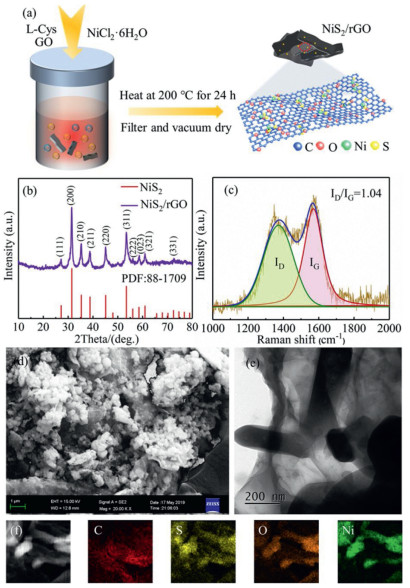
The fabrication process of the NiS2/rGO nanocomposite is illustrated in Fig. 1a. L-Cys plays the role of sulfur source and reductant for hydrothermal reaction (details in Supporting information). The NiS2 formed by L-cys and Ni2+ can easily electrostatically adsorb with oxygen-containing functional groups in graphene oxide [12], thereby forming the strong S—O bonds. X-ray diffraction (XRD) was used to characterize the crystal structure of the material, and the results are shown in Fig. 1b. It can be seen from the spectrum that all of the XRD peaks of NiS2/rGO can agree well with the cubic pyrite NiS2 (PDF No. 88-1709). It can be noticed that NiS2/rGO nanocomposite does not show diffraction peaks of graphene, indicating that the growth of NiS2 on the surface of graphene inhibits the stacking of graphene sheets [13]. In order to further study the existence form of carbon, Fig. 1c is the Raman diagram of NiS2/rGO nanocomposite. The two strong peaks at 1372.6 cm-1 and 1570.1 cm-1 correspond to the D peak and G peak respectively, confirming the presence of rGO.

|
Download:
|
| Fig. 1. (a) Schematic of synthesis of the NiS2/rGOnanocomposite. (b) XRD patterns and (c) Raman spectra of NiS2/rGO nanocomposite. (d) SEM image of NiS2/rGO. (e, f) TEM image and corresponding element mappings of NiS2/rGO. | |
The morphology of NiS2/rGO nanocomposite was shown in Figs. 1d–f. It can be seen from the SEM image of Fig. 1d that the agglomerated spherical NiS2 particles are distributed on the surface of the graphene sheet, and the particle size is in the order of hundreds of nanometers. Considering that the sample was ultrasonically treated before the SEM test, NiS2 nanoparticles and graphene nanoplatelets are still well combined, indicating that there is a strong interaction between NiS2 and rGO. Figs. 1e and f are TEM images of NiS2/rGO and corresponding element mappings. It can be seen that the nanocomposite contains C and O elements, which are derived from the reduced graphene oxide and the oxygen-containing functional groups in the rGO, respectively. It can be noted that the similar segregated regions of the O element correspond to the Ni and S elements, indicating that there is some interaction between O and NiS2.
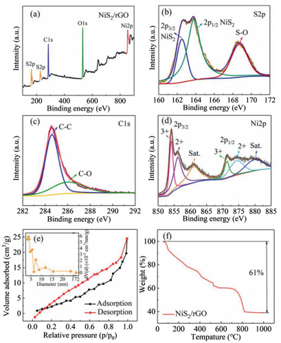
The elemental compositions and the chemical states on the surface of NiS2/rGO were further determined by X-ray photoelectron spectroscopy (XPS). Fig. 2a shows the XPS survey spectrum of NiS2/rGO, indicating the only existence of S, C, O and Ni elements. As presented in Fig. 2b, three peaks could be fitted in the high-resolution spectrum of S 2p, assigned to the Ni-S bond (162.5–163.8 eV) and the strong interaction of S—O bond (168.7 eV), respectively [14]. The C 1s (Fig. 2c) displays two obvious peaks located at 284.6 eV and 286.1 eV, which respectively correspond to the C—C and C—O bonds in NiS2/rGO [15]. The Ni 2p (Fig. 2d) can be divided into spin-orbit doublets and two shakeup satellites. The peaks situated at 856.1 and 874.6 eV are assigned to 2p3/2 and 2p1/2 of Ni2+. While the peaks located at 854.1 and 871.3 eV are attributed to 2p3/2 and 2p1/2 of Ni3+ [16]. This indicates that the transition metal Ni has multiple different oxidation states, and higher Na-ion storage capacity can be obtained through an effective redox reaction.

|
Download:
|
| Fig. 2. (a) XPS survey spectrum of nanocomposite. High-resolution XPS spectra of (b) S 2p, (c) C 1s and (d) Ni 2p. (e) N2 adsorption/desorption isotherms and pore size distribution (the inset) of NiS2/rGO. (f) TG curve of NiS2/rGO. | |
The N2 adsorption/desorption isotherm (Fig. 2e) of NiS2/rGO represents a typical type-Ⅳ behavior corresponds to the mesoporous structure. This implies that there exists a large number of mesopores in NiS2/rGO (Table S1 in Supporting information), which exhibits a high specific surface area of 14.76 m2/g. In detail, the BJH pore size of NiS2/rGO is in the range of 3–6 nm from the inset of Fig. 2e. Large specific surface area promotes the capacitance behavior in the electrochemical reaction, thus providing more discharge capacity [17]. Besides, high porosity is conducive to the full infiltration and flow of electrolyte, which plays an essential role in improving the rate performance [18]. The characteristic TG curve of NiS2/rGO (Fig. 2f) can be observed in the TG method in the air with the carbon content. The initial slight weight loss can be assigned to the loss of adsorbed water, and the notable weight loss between 250~1000 ℃ corresponds to the decomposition of graphene and oxygen-containing functional groups [19]. The emergence of the platform between 600–700 ℃ is caused by the oxidation of NiS2 to the final product NiO, increasing in weight [20]. Because 39.0 wt% of the original mass is retained, the contents of NiS2 and graphene in NiS2/rGO are 64.3 wt% and 35.7 wt%, respectively.
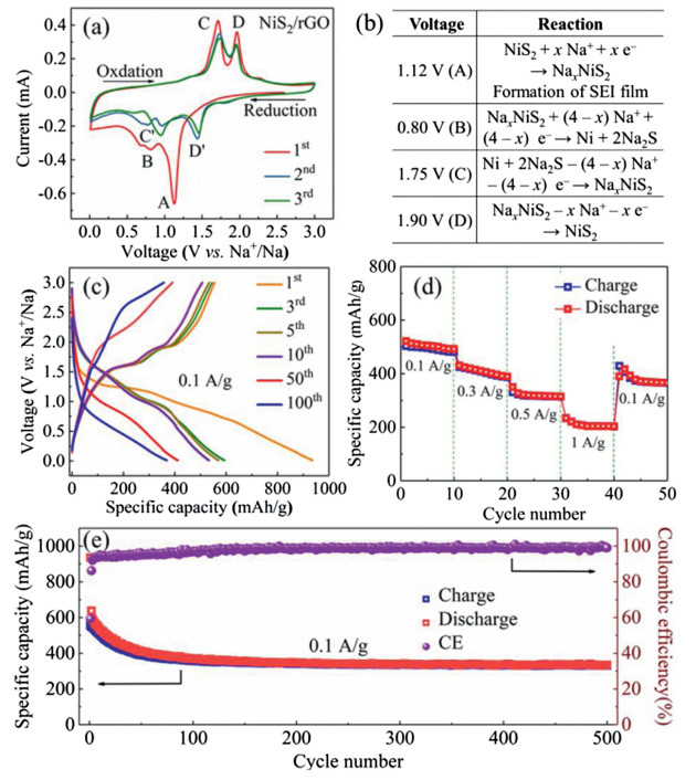
Cyclic voltammetry (CV) was performed on NiS2/rGO at the scan rate of 0.1 mV/s for the first three cycles, as shown in Fig. 3a. It can be seen from the figure that there is a strong irreversible reduction peak at 1.12 V (A) during the first discharge (sodium insertion), which corresponds to the formation of NaxNiS2 and SEI films [21]. The bump at 0.80 V (B) corresponds to the Na+ insertion into the NaxNiS2 crystal lattice to form Na2S [22]. Two oxidation peaks are displayed at about 1.75 V (C) and 1.90 V (D), which represent the oxidation of Na2S to NaxNiS2 and the formation of NiS2 [20]. In addition, the potential and intensities of redox peaks have good symmetry and consistency during the 2nd and 3rd cycles, indicating the excellent electrochemical performance of the conversion. The corresponding equations of the redox peaks in the CV curves can be elucidated in Fig. 3b.

|
Download:
|
| Fig. 3. (a) Cyclic voltammetry curves of NiS2/rGO. (b) The corresponding equations of the redox peaks in the cyclic voltammetry curves. (c) Discharge/charge curves at a current density of 0.1 A/g. (d) Rate capability at different rates (increased from 0.1 A/g to 1 A/g). (e) Cycling performance at a current density of 0.1 A/g. | |
The discharge/charge curves of various cycles of the NiS2/rGO at a current density of 0.1 A/g are revealed in Fig. 3c. There is a visible platform at 1.2–0.8 V during the first discharge of NiS2/rGO anode, which corresponds to the sodium insertion reaction of NiS2/rGO and the formation of SEI film [21]. Because the formation of SEI film is an irreversible process, the platform gradually weakens and migrates to lower potential in the subsequent discharge process (Fig. S1 in Supporting information). In the first charge process, the two platforms, which are more obvious at 1.5 V and 1.9 V, correspond to the oxidation reaction process in which Na2S gradually removes sodium to form NiS2. It is highly consistent with the following charge platform, and corresponds to the oxidation peak of the cyclic voltammetry curves in Fig. 3a.
The applicability of NiS2/rGO as anode materials is further evaluated through rate capability in Fig. 3d. Specifically, after activation for first three cycles, the NiS2/rGO anode affords reversible capacities of 492.3, 388.8, 314.7 and 203 mAh/g, respectively, at rates of 0.1, 0.3, 0.5 and 1 A/g. Note that the capacity of the NiS2/rGO anode can be recovered to 365.9 mAh/g and remains stable when the current rate was reverted to 0.1 A/g. The outstanding rate performance is mostly ascribed to the graphene sheet with the high specific surface area for efficient electron transport and mesoporous for fast penetration of electrolyte [23].
The stability of NiS2/rGO anode is verified by cycling the nanocomposite at the current density of 0.1 A/g. Fig. 3e depicts the electrochemical performance of the NiS2/rGO after a galvanostatic discharge/charge test of 500 cycles. It can be seen that the initial discharge/charge capacities were 935.6/555.2 mAh/g, and the FCE was reckoned as 59.3%. The loss capacity during the first cycle was attributed to the formation of SEI film [24]. Moreover, the reversible capacity of NiS2/rGO nanocomposite slowly decreases in the first 60 cycles and then keeps a stable value and reaches 334.4 mAh/g after 500 cycles with a CE of nearly 100%, corresponding to 52.6% capacity retention, which is better than the electrochemical performance of reported nickel sulphide based anodes (Table S2 in Supporting information). The excellent cycle performance and high reversible capacity of the as-prepared NiS2/rGO could be attributed to the nanocomposite structure and chemical restraint. On the one hand, the excellent flexibility of graphene effectively could buffer the volume expansion of NiS2 during intercalation/extraction of Na+ [13]. On the other hand, S—O bond with strong chemical action inhibits the dissolution of sulfur intermediates and sustains the capacity retention during long-term cycling.
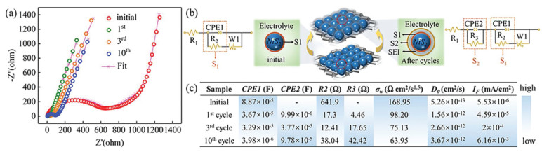
The interfacial properties of the charge transport/transfer havebeen measured by the EIS technic on the NiS2/rGO after various cycles under similar conditions. The initial and subsequent EIS (the 1st, 3rd, 10th cycles), as well as corresponding equivalent circuit model and fitting curves are shown in Figs. 4a and b, respectively. It can be seen from the fitting results that the initial EIS of NiS2/rGO consists of a semicircle (interface S1 between NiS2 and electrolyte) in the high-frequency region and a straight line in the low-frequency region. Another semicircle (interface S2 between SEI and electrolyte) was added to the EIS diagram of NiS2/rGO after cycling, which was caused by the formation of SEI film [25]. The EIS curve was fitted and the parameters obtained included electrolyte contact resistance (R1) space charge capacitance (CPE1, CPE2), charge transfer resistance (R2, R3) and Warburg impedance (W1). Warburg coefficient (σw), Faraday current density (IF) of S1 interface and the diffusion coefficient of Na+ (D0) calculated by Eqs. (1)–(3) [26] are shown in Fig. 4.

|
Download:
|
| Fig. 4. (a) Nyquist curves, (b) equivalent circuit models and (c) corresponding fitting parameters of NiS2/rGO anode with different cycles. | |

|
(1) |

|
(2) |
|
(3) |
Here, Rct is charge-transfer resistance, ω is the angular frequency, T is the temperature (298 K), A is the surface area of the electrode, F is the Faraday constant 96, 500 C/mol, C is the molar concentration of Na+ and n is the number of electrons transferred per molecule during the intercalation.
It can be seen from Fig. 4c that after 10 cycles, R2 reduces from 641.9 Ω to 12.41 Ω, accompanied by its space charge capacitance CPE1 reduces from 8.87 × 10⁻⁵ F to 3.98 × 10⁻⁶ F, and the corresponding IF increases from 5.53 × 10⁻⁶ mA/cm2 to 6.16 × 10⁻³ mA/cm2, which shows that with the decrease of the charge transfer resistance at the interface S1, the space charge accumulated at the interface is gradually destroyed, thus accelerating the diffusion of Na+ into the active material [27]. In addition, R3 and CPE2 increased from 4.46 Ω and 9.99 × 10⁻⁶ F to 42.42 Ω and 9.78 × 10⁻⁵ F during the 1st cycle to the 10th cycle, respectively, which is attributed to the resistance of electrolyte penetration at S2 interface, caused by the incomplete and unstable structure of SEI film formed after the first cycle [28]. The diffusion coefficient of Na+ (D0) increases and Warburg coefficient W1 decreases during the whole cycle, which may be due to the graphene skeleton with a mesoporous structure providing a transport channel for the rapid migration of Na+.
In summary, NiS2/rGO nanocomposite was prepared by L-cys assisted hydrothermal method. NiS2/rGO nanocomposite, as the anode material of Na-ion batteries, shows excellent cycle performance (reversible specific capacity reaches 334.4 mAh/g after 500 cycles at a current density of 100 mA/g) and rate performance (reversible specific capacity reaches 203 mAh/g at a current density of 1000 mA/g). The excellent cycle stability of NiS2/rGO comes from the chemical restraint of the S—O bond and the buffering effect of the graphene skeleton. Through further analysis of EIS, it is proved that the mesoporous structure of rGO accelerates the migration of Na+ in the active material.
Declaration of competing interestThe authors declare that they have no known competing financial interests or personal relationships that could have appeared to influence the work reported in this paper.
AcknowledgmentsThe authors gratefully acknowledge the support from the National Natural Science Foundation of China (NSFC, No. 51171033) and The Fundamental Research Funds for the Central Universities (No. DUT19LAB29).
Appendix A. Supplementary dataSupplementary material related to this article can be found, in the online version, at doi:https://doi.org/10.1016/j.cclet.2020.02.042.
| [1] |
N. Nitta, F.X. Wu, J.T. Lee, G. Yushin, Mater. Today 18 (2015) 252-264. DOI:10.1016/j.mattod.2014.10.040 |
| [2] |
D. Kundu, E. Talaie, V. Duffort, L.F. Nazar, Angew. Chem. Int. Ed. 54 (2015) 3431-3448. DOI:10.1002/anie.201410376 |
| [3] |
Y. Kim, Y. Park, A. Choi, et al., Adv. Mater. 25 (2013) 3045-3049. DOI:10.1002/adma.201204877 |
| [4] |
H. Hou, X. Qiu, W. Wei, et al., Adv. Energy Mater. 7 (2017) 1602898. DOI:10.1002/aenm.201602898 |
| [5] |
M. Lao, Y. Zhang, W. Luo, et al., Adv. Mater. 29 (2017) 1700622. DOI:10.1002/adma.201700622 |
| [6] |
J. Mei, T. Liao, L. Kou, et al., Adv. Mater. 29 (2017) 1700176. DOI:10.1002/adma.201700176 |
| [7] |
W.X. Zhao, S.Q. Ci, X. Hu, J.X. Chen, Z.H. Wen, Nanoscale 11 (2019) 4688-4695. DOI:10.1039/C9NR00160C |
| [8] |
X.L. Fan, Y J., H F.D., et al., ACS Nano 12 (2018) 3360-3368. DOI:10.1021/acsnano.7b08856 |
| [9] |
Q. Chen, S. Sun, T. Zhai, et al., Adv. Energy Mater. 8 (2018) 1800054. DOI:10.1002/aenm.201800054 |
| [10] |
R. Sun, S. Liu, Q. Wei, et al., Small 13 (2017) 1701744. DOI:10.1002/smll.201701744 |
| [11] |
S. Yang, X. Feng, S. Ivanovici, et al., Angew. Chem. Int. Ed. 49 (2010) 8408-8411. DOI:10.1002/anie.201003485 |
| [12] |
X.M. Sun, Z. Ji, M.X. Xiong, W. Chen, J. Electrochem. Soc. 164 (2017) B107-B112. DOI:10.1149/2.0831704jes |
| [13] |
Q.N. Chen, W.X. Chen, J.B. Ye, Z. Wang, J.Y. Lee, J. Power Sources 294 (2015) 51-58. DOI:10.1016/j.jpowsour.2015.06.071 |
| [14] |
G.G. Zhao, Y. Zhang, L. Yang, et al., Adv. Funct. Mater. 28 (2018) 1803690. DOI:10.1002/adfm.201803690 |
| [15] |
J.Y. Yu, H.T. Yu, J. Gao, et al., J. Alloys Compd. 693 (2017) 500-509. DOI:10.1016/j.jallcom.2016.09.232 |
| [16] |
A.A. AbdelHamid, X.F. Yang, J.H. Yang, et al., Nano Energy 26 (2016) 425-437. DOI:10.1016/j.nanoen.2016.05.046 |
| [17] |
J.L. Zhu, Y.Y. Li, S. Kang, X.L. Wei, P.K. Shen, J. Mater. Chem. A 2 (2014) 3142-3147. DOI:10.1039/c3ta14562j |
| [18] |
J. Xu, L. Shen, K. Shi, et al., ChemistrySelect 3 (2018) 10869-10874. DOI:10.1002/slct.201802425 |
| [19] |
D.X. Wu, C.Y. Wang, M.G. Wu, et al., J. Energy Chem. 43 (2020) 24-32. DOI:10.1016/j.jechem.2019.08.003 |
| [20] |
J.B. Li, J.L. Li, D. Yan, et al., J. Mater. Chem. A 6 (2018) 6595-6605. DOI:10.1039/C8TA00557E |
| [21] |
R.M. Sun, S.J. Liu, Q.L. Wei, et al., Small 13 (2017) 1701744. DOI:10.1002/smll.201701744 |
| [22] |
T.S. Wang, P. Hu, C.J. Zhang, et al., ACS Appl. Mater. Interfaces 8 (2016) 7811-7817. DOI:10.1021/acsami.6b00179 |
| [23] |
B.H. Qu, C.Z. Ma, G. Ji, et al., Adv. Mater. 26 (2014) 3854-3859. DOI:10.1002/adma.201306314 |
| [24] |
W.B. Pi, T. Mei, J. Li, et al., Chem. Eng. J. 335 (2018) 275-281. DOI:10.1016/j.cej.2017.10.142 |
| [25] |
C.J. Liu, F.H. Xue, H. Huang, et al., Electrochim. Acta 129 (2014) 93-99. DOI:10.1016/j.electacta.2014.02.031 |
| [26] |
Y. Cui, X.L. Zhao, R.S. Guo, Electrochim. Acta 55 (2010) 922-926. DOI:10.1016/j.electacta.2009.08.020 |
| [27] |
X.Z. Jin, H. Huang, A.M. Wu, et al., ACS Nano 12 (2018) 8037-8047. DOI:10.1021/acsnano.8b02861 |
| [28] |
H. Huang, S. Gao, A.M. Wu, et al., Nano Energy 31 (2017) 74-83. DOI:10.1016/j.nanoen.2016.10.059 |