 2020, Vol. 31


b State Key Laboratory of Mechanical Transmission, College of Materials Science and Engineering, Chongqing University, Chongqing 400044, China
Among various negative electrode materials of supercapacitors, iron materials own a wide potential window and high specific capacitance [1-6]. According to the theoretical specific capacitance formula C = nF/MV, Fe3O4, FeOOH and Fe2O3 can reach 2299 F/g, 2606 F/g and 3625 F/g relatively. Comparing with other transition metal oxides, iron oxide materials are more environmentally friendly and less toxic [7-10]. FeOOH, as an iron oxide, has several advantages of low cost, high theoretical capacitance and wide potential window. FeOOH with open pore structure, which can facilitate ion transportation, is a promising negative electrode material. Nevertheless, FeOOH has its inherent disadvantages. For example, the poor electrical conductivity (10-14 S/cm) leads to a higher charge transfer resistance between electrodes and electrolytes [11-14]. Due to its limited conductivity, its electrochemical capacitance is far lower than theoretical value. Moreover, FeOOH is prone to agglomerate during preparation. The tunnel structure of FeOOH tends to re-expand and collapse during charging and discharging, resulting in β-FeOOH transforming into α-FeOOH. As a result, FeOOH usually has poor cyclic stability. In terms of recent progress in overcoming these limits of FeOOH electrodes, the composition of FeOOH with carbon cloth composites, graphene composites and polypyrrole composites were reported [15]. Wherein, layered double metal hydroxides (LDHs) are a good choice to be electrode materials. In recent years, LDHs has received extensive attention in the field of electrochemistry. LDHs, as a typical two-dimensional (2D) layered pseudocapacitance material, have the characteristics of openness, easy adjustment of metal ions and abundant redox-active sites [16, 17]. Meanwhile, LDHs are easy to prepare and simply chemically modify, low cost, low environmental pollution, and meet the requirements of sustainable development [18]. At present, research on NiFe-LDH materials has become a hot topic in various fields. NiFe-LDH is formed by Fe3+ ions partially replacing Ni2+ in α-Ni(OH)2, meanwhile Fe3+ can enhance the conductivity of NiOOH [19].
In this work, the NiFe-LDH@FeOOH negative material was first prepared on nickel foam by the sacrificial template method. Nickel foam (NF) has the advantages of large pore structure, high specific surface area and strong physical strength. It is a promising material for current collectors in supercapacitors. NiFe-LDH was grown in-situ on nickel foam without the binder, which can reduce internal resistance and improve conducting performance. In the process of preparation, MnO2 was first grown on NiFe-LDH. Through sacrificing template method, FeOOH was subsequently prepared. The main reason for growing MnO2 on NiFe-LDH are as follows: (1) FeOOH produced by replacing MnO2 more closely integrated with NiFe-LDH; (2) In the two-electrode system, NiFeLDH@MnO2 can be directly used as the positive electrode of supercapacitors, which allow us to produce a full set of supercapacitor within one synthetic system. The NiFe-LDH@FeOOH electrode in a three-electrode system presents high specific capacitance (1195 F/g at a current density of 1 A/g), lower resistance and well cycling performance (90.36% retention after 1000 cycles). Furthermore, an asymmetrical supercapacitor was fabricated using the NiFe-LDH@MnO2 as the positive electrode and NiFe-LDH@FeOOH as the negative electrodes. At a power density of 750 W/kg, the energy density can reach 22.68 Wh/kg. Therefore, the electrode material might be useful for commercial applications in the future.
The preparation process of NiFe-LDH@FeOOH composite material based on nickel foam is shown in Fig. 1. First of all, NiFe-LDH was grown in situ on nickel foam. 35 mL of mixed solution was made with Ni(NO3)2·6H2O (2.0 mmol), Fe(NO3)3·9H2O (0.5 mmol) and urea (25 mmol). Then the nickel foam (1 cm × 1.5 cm) which was previously washed with distilled water and ethanol respectively was put into the mixed solution and sonicated for 10 min. The mixed solution and the nickel foam were kept in a Teflon lined stainless steel autoclaves at 120 ℃ for 16 h. The as-prepared product on Ni foam was NiFe-LDH. Secondly, the NiFe-LDH sample was soaked in 35 mL of 0.01 mol/L KMnO4 solution and then hydrothermally treated at 160 ℃ for 6 h. The as-prepared product on NiFe-LDH was NiFe-LDH@MnO2. Thirdly, the NiFe-LDH@MnO2 sample was put into 35 mL of 0.01 mol/L FeSO4·7H2O solution, followed by hydrothermal treatment at 120 ℃ for 2 h. The as-prepared sample was NiFe-LDH@FeOOH.

|
Download:
|
| Fig. 1. Schematic illustrations of the NiFe-LDH@FeOOH grown on a Ni foam. | |
The phase purity and crystallographic information of the as-prepared products were investigated by Powder X-ray diffraction (XRD, D/max 2500, Cu Kα) X-ray photoelectron spectroscopy (XPS, Kratos XSAM800). In order to observe the morphologies and compositions, field emission transmission electron microscopy (FETEM/FEI Talos F200S G2) and focused ion beam scanning electron microscopy (ZEISS AURIGA FIB/SEM) equipped with an energy dispersive X-ray spectrometry (EDS) were employed. The CH Instruments CHI660E was used for electrochemical tests.
The electrochemical properties of LDH@FeOOH materials were investigated in an aqueous 6 mol/L KOH electrolyte with a three-electrode cell. The as-prepared samples were directly used as the working electrode, a Pt plate as the counter electrode, and a standard calomel electrode (SCE) as the reference electrode. In a two-electrode system, an asymmetrical supercapacitor is composed of NiFe-LDH@ MnO2 as the positive electrode, NiFeLDH@FeOOH as the negative electrode, and filter paper as the separator.
The specific capacitances (Cm) are calculated according to the following equation:

|
where I is the discharge current (A), m is the weight (g) of active materials, Δt is the discharge time (s), and ΔV is the discharging potential window (V).
The morphology of NiFe-LDH@MnO2 was examined first by SEM. As shown in Figs. 2a and b, the nanoflakes are connected to each other in a wrinkled porous shape. The open spatial structure not only increases the specific surface area but also promotes the transportation of ions, which is beneficial to the electrochemical performance of the electrode. Figs. 2c and d show the morphology of NiFe-LDH@FeOOH. AfterMnO2replacement reaction, FeOOH growing on the NiFe-LDH well maintained the porous laminarstructure. Obviously, FeOOH sheets are denser and coarser than MnO2 templates and partially cluster into a spherical rod shape. Moreover, the specific surface area of the composite material increased, which is beneficial to the electrochemical performance. Figs. 2e and f are the SEM images of NiFe-LDH, the morphology of NiFe-LDH is lamellar. Taken together, we can clearly observe the changes in the morphology of the composite material during the preparation process.

|
Download:
|
| Fig. 2. SEM images of (a, b) NiFe-LDH@MnO2, (c, d) NiFe-LDH@FeOOH and (e, f) NiFe-LDH. | |
The as-prepared NiFe-LDH was further analyzed by TEM. As shown in Figs. 3a and b, the morphology of NiFe-LDH sample on the Ni foam is regular sheet corresponding with the unique 2D layered structure of LDH. Based on element mapping test of NiFe-LDH@MnO2 in Fig. 3d, it was found that every elements of Ni, Fe, O and Mn evenly distribute in 3D structure, which proves the successful maintenance of NiFe-LDH and preparation of MnO2 onside. The morphology in Fig. 3c becomes wrinkled. After further FeOOH growth, the elements test of NiFe-LDH@FeOOH sample in Fig. 3f showed existence of Ni, Fe and O, but the signal of Mn elements is negligible, which demonstrates that MnO2 was successfully removed and replaced with FeOOH. Meanwhile, the FeOOH sheets in Fig. 3e become coarser. The chemical reactions are as follow [20, 21]:

|
Download:
|
| Fig. 3. TEM images of (a) NiFe-LDH, (c) NiFe-LDH@MnO2 and (e) NiFe-LDH@FeOOH. The EDS mappings of (b) NiFe-LDH, (d) NiFe-LDH@MnO2 and (f) NiFe-LDH@FeOOH. | |

|
(1) |

|
(2) |
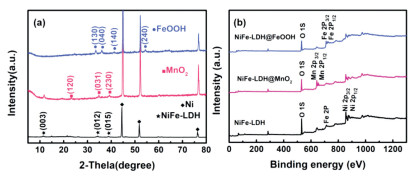
In order to further confirm that NiFe-LDH, NiFe-LDH@MnO2 and NiFe-LDH@FeOOH were successfully prepared on nickel foam, XRD and XPS tests were performed. In Fig. 4a, the XRD diffraction peaks of three samplescan be well indexed, indicating a successful preparation of NiFe-LDH, NiFe-LDH@MnO2 and NiFe-LDH@FeOOH. From the survey XPS spectra of the three samples in Fig. 4b, the transition from NiFe-LDH@MnO2 to NiFe-LDH@FeOOH agreed with TEM element mapping test, where the manganese element changed from existence to disappearance. It indicates that the NiFe-LDH@FeOOH sample was successfully prepared.

|
Download:
|
| Fig. 4. (a) XRD patterns and (b) survey XPS spectra of NiFe-LDH, NiFe-LDH@MnO2 and NiFe-LDH@FeOOH. | |
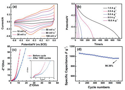
The initial electrochemical performances of NiFe-LDH@FeOOH are measured by a three-electrode system in 6 mol/L KOH solution (Fig. 5). As shown in Fig. 5a, with the gradual increase in scanning rate, the shape of the cyclic voltammetry curve remains basically the same, indicating that it has good electron and ion transport characteristics. There is an obvious redox peak between -0.6-0 V due to the reversible redox conversion of Fe2+ and Fe3+. Fig. 5b is galvanostatic charge-discharge curves of NiFe-LDH@FeOOH. Through calculation, the specific capacitance of the electrode is 1195, 965, 885, 784 and 456.7 F/g at 1, 2, 5, 8 and 10 A/g. As shown in Fig. 5c, the intrinsic internal resistance of the electrode is 1.2 Ω and the charge transfer resistance is 1.5 Ω. Clearly, the high capacitive property and nice electric conductivity are ascribed to the porous structure and high specific surface area for efficient transportation of electrons and ions within the electrode. Fig. 5d depicts the cycling stability of the NiFe-LDH@FeOOH by chargingdischarging tests at a current density of 1 A/g for consecutive 1000 cycles. It is obvious that the specific capacitance of the electrode maintains 90.36% of initial capacitance after 1000 cycles. The excellent capacitance performance of NiFe-LDH@FeOOH might be attributed to the synergistic effect of the nanocomposite structure. In details: (1) The modified FeOOH sheets on the NiFe-LDH have a porous nanostructure, which not only provides a large number of electroactive sites, but also makes it adequately contact with the electrolyte; (2) The 2D layered structure nanosheets of NiFe-LDH can enhance the diffusion of ions in the active material, accelerate the reaction kinetics, and can store more charges on the electrode per unit time; (3) The electrode material is grown in-situ on the nickel foam without a binder. Meanwhile, nickel foam has high conductivity, which can improve the mobility of electron carriers.

|
Download:
|
| Fig. 5. (a) CV curves of NiFe-LDH@FeOOH measured at different scan rates. (b) Galvanostatic charge-discharge curves at different current densities. (c) Electrochemical impedance spectrum before and after cycling at open circuit potential in the frequency range from 0.01 Hz to 100 kHz, the insets show the enlarged part of Nyquist plots. (d) Cycling performance of the electrode at a current density of 1 A/g. | |
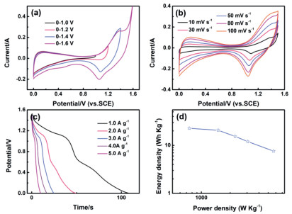
In order to explore the practical application of the NiFeLDH@FeOOH electrode, an asymmetrical supercapacitor was assembly by positive electrode NiFe-LDH@MnO2 prepared in the second synthetic step and negative electrode NiFe-LDH@FeOOH with 6 mol/L KOH as an electrolyte. Fig. 6a shows the CV curves. The potential window can reach 1.6 V and the basic shape of the CV curve remains the same, indicating its good capacitance performance. There are obvious redox peaks in the Fig. 6b, which indicates that it has a pseudocapacitive characteristic. At different scan rates, the area of the CV curve gradually increases, while the shape remains basically the same, exhibiting well ion transport stability. Fig. 6c is galvanostatic charge–discharge curves. The plateau in curves correspond to the redox reaction. By calculation, the specific capacitance can reach 72.6 F/g at a current density of 1 A/g. As shown in Fig. 6d, at a power density of 750 W/kg, the energy density can reach 22.68 Wh/kg. The NiFe-LDH@FeOOH electrode has good electrochemical performance and broad application prospects.

|
Download:
|
| Fig. 6. (a) CV curves of the NiFe-LDH@MnO2//NiFe-LDH@FeOOH supercapacitor measured at different potential windows. (b) CV curves of the asymmetric supercapacitor measured at different scan rates between 0 and 1.5 V. (c) Galvanostatic charge–discharge curves at different current densities. (d) A Ragone plot of the NiFe-LDH@MnO2//NiFe-LDH@FeOOH supercapacitor. | |
In conclusion, NiFe-LDH, NiFe-LDH@MnO2 and NiFeLDH@FeOOH electrode materials have been synthesized in-situ on nickel foam by hydrothermal method and the electrochemical performance tests have been performed. The unique 2D layered structure of NiFe-LDH has both a high specific surface area to provide active sites, and a highly open layered structure. As a composite carrier, it can provide good structure and morphology for subsequent loads. The experimental results show that the NiFeLDH@FeOOH negative material exhibits high specific capacitance (1195 F/g at a current density of 1 A/g), lower resistance and well cycling performance (90.36% retention after 1000 cycles). In addition, in two-electrode system, theNiFe-LDH@MnO2//NiFeLDH@FeOOH supercapacitor exhibits 22.68 Wh/kg energy density at a power density of 750 W/kg. NiFe-LDH modified by FeOOH nanosheets as a negative electrode material greatly improves the electrochemical performance of itself, which provides an important reference value for the development of negative electrode materials.
Declaration of competing interestThe authors declare that they have no known competing financial interests or personal relationships that could have appeared to influence the work reported in this paper.
AcknowledgmentsThis work received financial support from the National Natural Science Foundation of China (Nos. 21576034 and 51908092), the State Education Ministry and Fundamental Research Funds for the Central Universities (Nos. 2019CDQYCL042, 2019CDXYCL0031, 2018CDYJSY0055, 106112017CDJQJ138802, 106112017CDJSK04XK11 and 106112017CDJXSYY0001), the Joint Funds of the National Natural Science Foundation of China-Guangdong (No. U1801254). The authors thank the Electron Microscopy Center, Analytical and Testing Center of Chongqing University for materials characterizations.
| [1] |
Y. Zeng, M. Yu, Y. Meng, Adv. Energy Mater. 6 (2016) 1601053. DOI:10.1002/aenm.201601053 |
| [2] |
K. Li, X. Liu, T. Zheng, Chem. Eng. J. 370 (2019) 136-147. DOI:10.1016/j.cej.2019.03.190 |
| [3] |
S. Zheng, Q. Li, H. Xue, H. Pang, Q. Xu, Nat. Sci. Rev. 137 (2019) 2095-5138. |
| [4] |
Y. Li, Y. Shan, H. Pang, Chin. Chem. Lett. (2020), doi: http://dx.doi.org/10.1016/j.cclet.2020.03.027.
|
| [5] |
T. Wang, X. Guo, H. Duan, C. Chen, H. Pang, Chin. Chem. Lett. 31 (2020) 654-666. DOI:10.1016/j.cclet.2019.06.002 |
| [6] |
Z. Liang, R. Zhao, T. Qiu, R. Zou, Q. Xu, Energy Chem. 1 (2019) 100001. DOI:10.1016/j.enchem.2019.100001 |
| [7] |
K. Wang, Q. Xun, Q. Zhang, Energy Chem. 2 (2020) 100025. DOI:10.1016/j.enchem.2019.100025 |
| [8] |
P. Geng, S. Zheng, H. Tang, R. Zhu, H. Pang, Adv. Energy Mater. 8 (2018) 1703259. DOI:10.1002/aenm.201703259 |
| [9] |
Y. Jiang, J. Liu, Energy Environ. Mater. 2 (2019) 30-37. DOI:10.1002/eem2.12028 |
| [10] |
R.Z. Li, J.P. Liu, Nanoscale Horiz. 1 (2016) 150-155. DOI:10.1039/C5NH00100E |
| [11] |
B. Deng, T. Lei, W. Zhu, L. Xiao, J. Liu, Adv. Funct. Mater. 28 (2018) 1704330. DOI:10.1002/adfm.201704330 |
| [12] |
W.H. Zuo, C.Y. Xie, J.P. Liu, Adv. Mater. 29 (2017) 1703463. DOI:10.1002/adma.201703463 |
| [13] |
W.H. Zuo, R.Z. Li, J.P. Liu, Adv. Sci. 4 (2017) 1600539. DOI:10.1002/advs.201600539 |
| [14] |
R.B. Pujari, S.J. Patil, K. Jongsung, B. Rahul, J. Power Sources (2019) 436. |
| [15] |
B. Shen, R. Guo, J. Lang, L. Liu, L. Liu, X. Yan, J. Mater. Chem. A 4 (2016) 8316-8327. DOI:10.1039/C6TA01734G |
| [16] |
Z. Xiao, Y. Mei, S. Yuan, ACS Nano 13 (2019) 7024-7030. DOI:10.1021/acsnano.9b02106 |
| [17] |
Y. Guo, X. Hong, ng Wa, Y. Guo, Adv. Funct. Mater. 29 (2019) 1809004. DOI:10.1002/adfm.201809004 |
| [18] |
X. Gao, X. Liu, D. Wu, Adv. Funct. Mater. 29 (2019) 1903879. DOI:10.1002/adfm.201903879 |
| [19] |
M. Li, R. Jiqie, A. Barras, P. Roussel, Electrochim. Acta 302 (2019) 1-9. DOI:10.1016/j.electacta.2019.01.187 |
| [20] |
G. Gao, Y. Le, B.W. Hao, W.L. Xiong, Adv. Mater. 10 (2014) 1741-1745. |
| [21] |
Y. He, B. Jiang, Y. Jiang, J. Chen, Y.X. Zhang, J. Hazard, Mater. 344 (2017) 230-240. |