 2020, Vol. 31


b Advanced Research Institute of Multidisciplinary Science, Beijing Institute of Technology, Beijing 100081, China;
c College of Materials and Energy, South China Agricultural University, Guangzhou 510642, China
The developing of modern society essentially requires the exploration of next-generation energy storage systems with intrinsic high energy density and low cost [1-3]. Nevertheless, current lithium ion batteries (LIBs), limited by the unsatisfactory capacity of graphite anode (372 mAh/g), are nearly approaching the theoretical value on energy density [4, 5]. It can hardly keep pace with the ever-increasing requirements from the boomingly developed electronic field. With the extremely high theoretical specific capacity (3860 mAh/g) and the most negative electrode potential (-3.040 V vs. standard hydrogen electrode), Li metal has been strongly regarded as a "Holy Grail" anode material. The next-generation Li metal batteries (LMBs), including Li–oxygen (Li–O2) and Li–sulfur (Li–S) batteries, exhibit great promise in largely upgrading the energy density [6-9]. However, the extremely unstable interfaces of traditional liquid LMBs results in poor cyclability, low Coulombic efficiency (CE) and serious safety issues, intrinsically hindering the process toward practical applications [10-12].
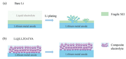
Derived from the inherent ultrahigh chemical reactivity, Li metal can react with almost all nonaqueous electrolytes, leading to the formation of heterogeneous solid electrolyte interphase (SEI), which further induces nonuniform Li ion transport and uneven Li deposition (Fig. 1a) [13-15]. During Li plating, the fragile SEI is easily broken by the sharp Li dendrites, and fresh Li will contact with liquid electrolyte directly with continuous SEI generation. Even worse, isolated "dead Li" will form during Li stripping due to the intrinsic heterogeneity of SEI, largely decreasing the reversibility of the cell [16]. As a result, the practical liquid LMBs always suffer from the increased interfacial resistance, low Coulombic efficiency, poor cycle performance and even safety concerns [17-19]. Thus, particular dedications should be devoted to overcome the inherent weakness to achieve a more stable Li/electrolyte interface [20-22].

|
Download:
|
| Fig. 1. Schematic of the deposition behavior of (a) bare lithium, dendrites forms after cycling. (b) LLZO-EVA composite electrolyte protected Li metal, dendrites penetration is well suppressed due to the stable interface. | |
In this consideration, tremendous efforts have been paid into regulating the in situ SEI by optimizing solvents [23], Li salts [24] and electrolyte additives [25, 26]. However, these in situ SEIs are always not robust enough to withstand the huge volume change of electrode, which leads to the ever-consuming of liquid electrolyte and the thickening of SEI [27, 28]. Solid-state electrolyte with high stability towards Li metal is expected to address these drawbacks [29-31]. Unfortunately, all-solid-state LMBs are currently facing severe challenges originated from the poor solid-solid interfacial contact and sluggish interfacial kinetics, which significantly increase the polarization and deteriorate the long cycle performance [32, 33].
Herein, a quasi-solid battery is developed by the incorporation of a composite integrated Li metal electrode protected by the solid electrolyte film and a limited amount of liquid electrolyte (7.5 μL/cm2). The composite solid electrolyte provides fast ion transport pathways, good mechanical strength at the anode side, which considerably suppresses the thermodynamic corrosion of Li metal anode. Meanwhile, a small amount of liquid electrolyte injected enables sustained wetting and superior interfacial contact. This unique quasi-solid strategy is expected to greatly reinforce the electrode/electrolyte stability and alleviate the safety anxiety of traditional liquid LMBs (Fig. 1b).
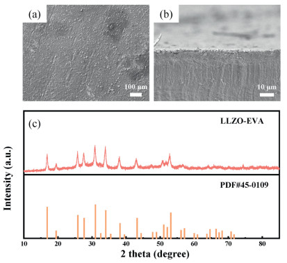
Garnet Al-doped Li6.75La3Zr1.75Ta0.25O12 (LLZO) and ethylenevinyl acetate copolymer (EVA) were chosen in this work to fabricate the composite solid electrolyte film onto Li metal. LLZO is widely accepted as a promising solid electrolyte with superior ionic conductivity of 10-4 S/cm and sufficient stability toward Li metal [34]. The Li@LLZO-EVA integrated electrode can be facilely obtained via an easy-processing doctor blading method. Firstly, 0.50 g EVA was dissolved in 1.2 mL xylene and the dispersion was vigorously stirred for 20.0 h at an elevated temperature of 50 ℃. After that, 0.50 g LLZO was added into the dispersion and magnetically stirred for 24 h. The mixed slurry was doctor bladed on the 50 μm ultra-thin Li belt, followed by drying at 60 ℃ for 24.0 h in argon (Ar)-filled glove box. Prior to use, the electrode was pouched into pieces with a diameter of 15.0 mm. The as-prepared Li@LLZO-EVA electrode processes a uniform morphology with LLZO inorganic particles well dispersed in the flexible EVA substrate (Fig. 2a). The composite electrolyte film has both essential mechanical strength and enough flexibility, suppressing dendrite penetration while adapting to the volume variation of the electrode during the cell cycling. From the cross-sectional angle, a 3 μm-thick LLZO-EVA film can be observed, which tightly binds to the Li metal surface to serve as an interfacial ion conducting layer (Fig. 2b). In fact, the thickness of the composite electrolyte film could be facilely regulated by adjusting the amount of precursor solution as well as the gap of scraper. Finally, an optimized thickness of 3 μm was obtained. The ultrathin property of the composite solid electrolyte film is expected to endow a minimum additional resistance for ion transport. X-ray diffraction (XRD) was employed to provide explicit information on the composition and phase state of the composite electrolyte film. As shown in Fig. 2c, strong crystallinity can be confirmed of the solid electrolyte film. The peaks match commendably with pure cubic-phase LLZO (PDF#45-0109). The highly ionic conductive cubic-phase LLZO (~10-4 S/cm) intrinsically ensures fast ion transport across the electrolyte with low ohmic polarization.

|
Download:
|
| Fig. 2. Morphological and structural characterizations. (a) Top-view SEM image and (b) side-view of the integrated Li@LLZO-EVA electrode. (c) XRD patterns of LLZOEVA film and pristine LLZO powders (PDF#45-0109). | |
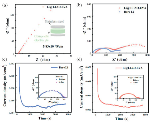
Systematic electrochemical tests were carried out to investigate the performance of the quasi-solid electrolyte film. Firstly, the ionic conductivity of the composite electrolyte film was measured at room temperature using blocking electrode method (Fig. 3a). A considerable value of 5.8 × 10⁻⁴ S/cm can be determined. The high ionic conductivity contributes to the low interfacial resistance (~350 Ω) of practical cell as exhibited in Fig. 3b, which is comparable to the liquid counterpart (~280 Ω). Additionally, the small resistance is also benefited from the conformal interfacial contact between the composite LLZO-EVA electrolyte film and Li metal, which is essential for achieving long-term protection during cycling.

|
Download:
|
| Fig. 3. Electrochemical tests. (a) The EIS obtained to determine the ionic conductivity of the LLZO-EVA film. The insert is the configuration of the cell with stainless steel electrodes. (b) EIS spectra of full cells with bare Li and LLZO-EVA modified Li; Current-time plots of (c) bare and (d) LLZO-EVA coated symmetric Li cell after the application of a constant potential (10 mV). The inserts are the impedance spectra before and after polarization. | |
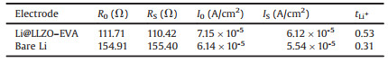
The Li+ transference number (tLi+) measurement was further conducted to quantitatively describe the Li+ transport behavior within the quasi-solid-state LLZO-EVA film. In detail, tLi+ was determined by the following equation:

|
where I0 and R0 are the initial current and resistance, respectively, Is and RS are the steady-state current and resistance, ΔV is the constant polarization voltage applied (10 mV). A low Li+ transfer number of 0.31 was determined (Fig. 3c and Table 1) in bare symmetric Li cell with liquid electrolyte (1.0 mol/L LiPF6 EC/DEC, v/v = 1/1). As for symmetric cell with Li@ LLZO-EVA electrode, the tLi+ increases from 0.31 to 0.53 (Fig. 3d and Table 1). The reason for the increase of tLi+ in the composite electrolyte should be the alternative Li+ transport channels provided by the LLZO-EVA film, which enables a more efficient interfacial Li+ migration manner.
|
|
Table 1 The parameters for Li+ transference number calculation. |
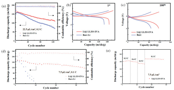
Full cells were assembled for an assessment of the quasi-solid strategy under practical conditions. LiNi0.5Co0.2Mn0.3 (NCM) cathode (~1.5 mg/cm2), ultrathin (50 μm) Li anode, and conventional carbonate electrolyte of 1.0 mol/L LiPF6 FEC/EC/DEC (v/v/v = 1/2/2) were used in the LiǀNCM cells. The full cells cycled using a LAND multichannel battery cycler in the voltage range of 3.0–4.3 V. At a relatively sufficient amount of electrolyte (22.5 μL/cm2), the cycling performance of LiǀNCM cells employing Li anodes with and without composite electrolyte film is quite distinct as shown in the Fig. 4a. An electrochemical activation step at 0.1 C (1.0 C = 170 mAh/g) was performed before the subsequent cycling at 0.3 C. At the beginning, both the cells with bare Li and Li@LLZO-EVA anodes exhibited high capacities of 155 mAh/g and high CEs of > 99%, while rather different in capacity decrease can be observed during the later cycling. The capacity of cell with bare Li dropped sharply to 100 mAh/g after 70 cycles (Fig. 4a). Contrastly, the cell with Li@LLZO-EVA anode illustrated much enhanced cycling performance with a considerable retained discharge capacity of 110.8 mAh/g after 125 cycles, indicating the improved interfacial stability of the quasi-solid battery than traditional liquid battery. The sharp capacity decrease is due to the augment of anode resistance and polarization as a result of severe accumulation of dead Li during plating/stripping in liquid battery. However, the polarization increase of the cell can be largely suppressed by the incorporation of LLZO-EVA solid electrolyte film. As demonstrated in Figs. 4b and c, the discharge midpoint voltage of the control cell significantly reduced from 3.77 V to 3.61 V. In contrast, the decrease of discharge midpoint voltage for the cell with Li@LLZO-EVA anode, from 3.77 V to 3.65 V, was less prominent. This should be originated from the stabilized electrode/electrolyte interface due to the protection of the composite LLZO-EVA electrolyte film.

|
Download:
|
| Fig. 4. (a) Cycle performance of Li-NCM cells with and without the LLZO-EVA film at 0.3 C (1.0 C = 170 mA/g). Voltage profiles of different cells at (b) 1st cycle and (c) 100th cycle. (d) Cycling stability of Li-NCM cells at 0.1 C with lean electrolyte (7.5 μL/cm2). (e) Rate performance of the LiǀNCM cell with Li@LLZO-EVA anode. | |
In the pursuit of high energy density, the amount of electrolyte and Li source in LMBs should be concurrently minimized to provide a practical cycling protocol. Based on this consideration, cell performance of the Li@LLZO-EVA anode was further evaluated under strict condition with lean electrolyte (7.5 μL/cm2), aiming to afford more meaningful insight into the performance of LMBs under practical conditions. As exhibited in Fig. 4d, the distinction on cycling stability of LiǀNCM cells was even more exaggerated. The traditional liquid battery can be hardly cycled under the harsh condition with such a tiny amount of electrolyte. The capacity straightly declined from 160 mAh/g to 40 mAh/g after just seven cycles. In contrast, the lifespan of the cell using this facile quasi-solid strategy was prolonged significantly. A high specific capacity of 115 mAh/g can be maintained after 35 cycles (Fig. 4d). The ameliorative cycle performance was ascribed to the alleviated consuming of liquid electrolyte during cycling, in virtue of the diminished SEI and porous "dead Li" layer generation. Rate performance of the LiǀNCM cells with Li@LLZO-EVA anode was further examined under lean electrolyte condition (7.5 μL/cm2). Considerable capacities of 150 mAh/g, 145 mAh/g, 135 mAh/g, 165 mAh/g can be achieved at 0.3 C, 0.4 C, 0.5 C, 0.1 C, respectively (Fig. 4e). The superior rate performance is strongly benefited from the fast ion transport ability of the solid electrolyte film and the conformal interfacial contact with low resistance.
This work demonstrates a feasible strategy of quasi-solidification to concurrently enable superior interfacial stability and enhanced safety of working LMBs. The rational design of an effective solid electrolyte film plays an indispensable role in the stabilization of Li metal/electrolyte interface, which provides sufficient ion channels, sustained interfacial contact and good mechanical stability at the anode side, enabling the stable cycling of LMBs even under lean liquid electrolyte. The quasi-solidification methodology provides a compromise path between the all-solid-state and liquid cells, shedding fresh light on the building of highdurability electrode/electrolyte interfaces.
Declaration of competing interestThe authors declare that they have no known competing financial interests or personal relationships that could have appeared to influence the work reported in this paper.
AcknowledgmentsThis work was supported by National Key Research and Development Program (No. 2016YFA0202500), National Natural Science Foundation of China (Nos. 21776019, 21808124) and Beijing Natural Science Foundation (No. L182021).
| [1] |
D.C. Lin, Y.Y. Liu, Y. Cui, Nat. Nanotechnol. 12 (2017) 194-206. DOI:10.1038/nnano.2017.16 |
| [2] |
X.Q. Zhang, C.Z. Zhao, J.Q. Huang, et al., Engineering 4 (2018) 831-847. DOI:10.1016/j.eng.2018.10.008 |
| [3] |
Y. Liang, C.Z. Zhao, H. Yuan, et al., InfoMat. 1 (2019) 6-32. DOI:10.1002/inf2.12000 |
| [4] |
J.W. Choi, D. Aurbach, Nat. Rev. Mater. 1 (2016) 16013. DOI:10.1038/natrevmats.2016.13 |
| [5] |
M. Tang, H. Li, E. Wang, et al., Chin. Chem. Lett. 29 (2018) 232-244. DOI:10.1016/j.cclet.2017.09.005 |
| [6] |
H.J. Peng, J.Q. Huang, X.B. Cheng, et al., Adv. Energy Mater. 7 (2017) 1700260. DOI:10.1002/aenm.201700260 |
| [7] |
Y.W. Chen, S.Z. Niu, W. Lv, et al., Chin. Chem. Lett. 30 (2019) 521-524. DOI:10.1016/j.cclet.2018.04.019 |
| [8] |
W. Chen, Y.F. Gong, J.H. Liu, Chin. Chem. Lett. 28 (2017) 709-718. DOI:10.1016/j.cclet.2016.10.023 |
| [9] |
J.L. Qin, H.Y. Zhao, J.Q. Huang, J. Energy Chem. 29 (2019) 1-2. DOI:10.1016/j.jechem.2018.07.001 |
| [10] |
M. Zhu, J. Wu, Y. Wang, et al., J. Energy Chem. 37 (2019) 126-142. DOI:10.1016/j.jechem.2018.12.013 |
| [11] |
X. Xu, S. Wang, H. Wang, et al., J. Energy Chem. 27 (2018) 513-527. DOI:10.1016/j.jechem.2017.11.010 |
| [12] |
B.Q. Li, X.R. Chen, X. Chen, et al., Research (2019) 4608940. |
| [13] |
W. Xu, J. Wang, F. Ding, et al., Energy Environ. Sci. 7 (2014) 513-537. DOI:10.1039/C3EE40795K |
| [14] |
Z.G. Gao, S.J. Zhang, Z.G. Huang, et al., Chin. Chem. Lett. 30 (2019) 525-528. DOI:10.1016/j.cclet.2018.05.016 |
| [15] |
R. Xu, B. X.-Cheng, C. Yan, et al., Matter 1 (2019) 317-344. DOI:10.1016/j.matt.2019.05.016 |
| [16] |
K. Zhang, G.H. Lee, M. Park, et al., Adv. Energy Mater. 6 (2016) 1600811. DOI:10.1002/aenm.201600811 |
| [17] |
X. Shen, H. Liu, X.B. Cheng, et al., Energy Storage Mater. 12 (2018) 161-175. DOI:10.1016/j.ensm.2017.12.002 |
| [18] |
L.L. Li, S.Y. Li, Y.Y. Lu, Chem. Commun. 54 (2018) 6648-6661. DOI:10.1039/C8CC02280A |
| [19] |
R. Xu, Y.Z. Sun, Y.F. Wang, et al., Chin. Chem. Lett. 28 (2017) 2235-2238. DOI:10.1016/j.cclet.2017.09.065 |
| [20] |
X.B. Cheng, C. Yan, X.Q. Zhang, et al., ACS Energy Lett. 3 (2018) 1564-1570. DOI:10.1021/acsenergylett.8b00526 |
| [21] |
Y. Yuan, F. Wu, G. Chen, et al., J. Energy Chem. 37 (2019) 197-203. DOI:10.1016/j.jechem.2019.03.014 |
| [22] |
M.D. Tikekar, S. Choudhury, Z. Tu, et al., Nat. Energy 1 (2016) 16114. DOI:10.1038/nenergy.2016.114 |
| [23] |
K. Xu, Chem. Rev. 114 (2014) 11503-11618. DOI:10.1021/cr500003w |
| [24] |
R. Miao, J. Yang, X. Feng, et al., J. Power Sources 271 (2014) 291-297. DOI:10.1016/j.jpowsour.2014.08.011 |
| [25] |
X.Q. Zhang, X.B. Cheng, Q. Zhang, Adv. Mater. Interfaces 5 (2018) 1701097. DOI:10.1002/admi.201701097 |
| [26] |
H. Kuwata, H. Sonoki, M. Matsui, et al., Electrochemistry 84 (2016) 854-860. DOI:10.5796/electrochemistry.84.854 |
| [27] |
R. Xu, Y. Xiao, R. Zhang, et al., Adv. Mater. 31 (2019) 1808392. DOI:10.1002/adma.201808392 |
| [28] |
C. Yan, H. Yuan, H.S. Park, et al., J. Energy Chem. 47 (2020) 217-220. DOI:10.1016/j.jechem.2019.09.034 |
| [29] |
J. Janek, W.G. Zeier, Nat. Energy 1 (2016) 16141. DOI:10.1038/nenergy.2016.141 |
| [30] |
X. Shen, X.B. Cheng, P. Shi, et al., J. Energy Chem. 37 (2019) 29-34. DOI:10.1016/j.jechem.2018.11.016 |
| [31] |
X. Wu, K. Pan, M. Jia, et al., Green Energy Environ. 4 (2019) 360-374. DOI:10.1016/j.gee.2019.05.003 |
| [32] |
X.B. Cheng, Q. Zhang, J. Mater. Chem. A 3 (2015) 7207-7209. DOI:10.1039/C5TA00689A |
| [33] |
R. Chen, W. Qu, X. Guo, et al., Mater. Horiz. 3 (2016) 487-516. DOI:10.1039/C6MH00218H |
| [34] |
R. Murugan, V. Thangadurai, W. Weppner, Angew. Chem. Int. Ed. 46 (2007) 7778-7781. DOI:10.1002/anie.200701144 |