 2020, Vol. 31


b Key Laboratory of Advanced Energy Materials Chemistry(Ministry of Education), Nankai University, Tianjin 300071, China
Lithium-ion batteries (LIBs) possess several merits of high energy density, good safety, and excellent cycling stability, enabling broad application prospects in renewable energy storage and electric vehicles development. However, the currently commercialized graphite negative electrodes with limited theoretic capacity of 372 mAh/g inhibit the evolution of energy storage field [1-5]. Therefore, there is an ever-increasing demand to search for new negative electrode materials to substitute graphite.
Transition metal oxides (TMOs) [6-8] are considered as the promising alternative negative materials on account of their excellent theoretical capacity (~900-1000 mAh/g) and low cost. Fe3O4 based on conversion reactions possesses some distinctive merits, for instance, high capacity (924 mAh/g) and high abundance [9, 10]. Nonetheless, the large volume diversification given rise to the conversion of the oxide and the metallic states during cycling could bring about the fracture of electrode materials, thus leading to a fast decay of capacity and reduced cycle performance [11].
Graphene or reduced graphene oxide, with high conductivity and unique two-dimensional structure, has been widely used as a structure buffer medium for metal oxide-based negative materials [12-14]. By virtue of the morphology effect of Fe3O4, Kumar and coworkers showed that octahedral Fe3O4 nanocrystals on reduced graphene oxide nanosheets (rGO) could improve the electrochemical property (540 mAh/g at 100 mA/g after 120 cycles) in comparison to nanoparticles on rGO (270 mAh/g) [15]. The works mentioned above presented the high capacity of Fe3O4 negative electrode, but the volume change of Fe3O4 on lithiation/delithiation will result in its detachment from graphene and finally cause electrode pulverization to deteriorate the electrochemical performance. Very recently, Li et al. demonstrated N-doped carbon layer coated Fe3O4 nanoparticle networks displayed enhanced lithium storage performance at high current density (1125 mAh/g at 1 A/g) [16]. Therefore, the N-doped carbon layer is expected to alleviate the challenging pulverization of Fe3O4/graphene nanocomposites anodes.
Herein, we propose a utilization of N-carbon as a riveting layer to improve the structure stability and conductivity of Fe3O4/graphene (Fe3O4/G) nanosheets, thereby affording a noteworthy reversible capacity of 807 mAh/g at 100 mA/g, excellent rate performances with long cycling stability, i.e., 550 mAh/g at 1 A/g over 700 turns. The correlations between structure and property of N-carbon-riveted Fe3O4/G nanocomposites have been systematically studied, which proves that the carbon riveting layer has a crucial effect in enhancing lithium storage properties.
In this work, Hummers method was used to produce the graphene oxide (GO) [17, 18]. In a typical process, dissolve graphite flakes (3.0 g) and NaNO3 (1.5 g) into H2SO4 and kept 0 ℃ in the ice bath. Then, KMnO4 (15 g) was put into the solution slowly and maintain the reaction condition below 20 ℃ under stirring for 30 min. Next, the reaction was adjusted to about 95 ℃ for 15 min while water was added slowly, and the solution was stirred over 15 min to remove heat. After that, 3 mL of H2O2 (30 wt%) and 420 mL of deionized water were added. The final products were obtained after centrifugation, washing and freeze-drying.
Then, 0.075 g as-prepared GO was added into a beaker with 150 mL of ethylene glycol with ultrasound dispersion for 1 h, then dissolve 1.01 g Fe(NO3)3·9H2O in the mixture which was put into Teflon-lined autoclaves with 100 mL capacity and maintained 150 ℃ for 2 h. The product of Fe3O4/reduced graphene oxide (Fe3O4/rGO) was prepared through centrifugation, washing three times using water, and freeze-drying. Then, Fe3O4/graphene (Fe3O4/G) was got after calcining at 700 ℃ for 1 h under Ar atmosphere.
In addition, 0.54 g of the Fe3O4/rGO was dissolved into a mixture of ethanol (40 mL) and pyrrole (0.586 mL). After ultrasonication for 20 min, 1 mol/L FeCl3 (10 mL) was poured to the mixture and mixed for 12 h. After centrifugation, washing, freezedrying and calcining at 700 ℃ for 1 h in the Ar atmosphere, the final black powders were carbon/Fe3O4/grapheme (C/Fe3O4/G).
Several methods were chosen to characterize the physical and chemical properties of the as-synthesized materials. X-ray diffraction (XRD, Rigaku Smart lab) with Ni-filtered Cu-Kα radiation (λ =1.5406 Å) at a voltage of 40 kV and a current of 40 mA was utilized to characterize the phase of two products. The elemental information was collected on X-ray photoelectron spectroscopy (XPS, Thermo ESCALAB 250, monochromatic Al-Kα radiation, 150 W). The morphology and size were examined by scanning electron microscopy (SEM, Zeiss sigma 300). The further detailed microstructure was recorded on transmission electron microscopy (TEM, JEM-2010) equipped with energy-dispersive X-ray spectroscopy (EDX) and high-resolution transmission electron microscopy (HRTEM, JEM-2010). The surface morphology and thickness were analyzed by atomic force microscope (AFM, Nanosurf NaioAFM). Raman was analyzed by Renishaw equipped with a 532 nm laser. Brunauer-Emmet-Teller (BET) testing via N2 adsorption-desorption isotherms was estimated by Quantachrome Autosorb iQ3. Thermo-gravimetric analysis (TGA, NETZSCH, TG209) was carried out under airflow at a heating rate of 10 ℃/min.
In addition, the electrochemical performances were also investigated. The electrodes were fabricated by grinding the active material, carbon black and polyvinylidene fluoride (PVDF) (7:2:1 wt%) in a mortar to make a homogeneous paste. The paste was uniform smear on Cu foil with a mass of approximately 1.2–1.4 mg/cm2. 1 mol/L solution of LiPF6 in dimethyl carbonate, ethylene methyl carbonate, and ethylene carbonate (1:1:1 in volume) was chosen to be electrolyte. The battery was fabricated in Ar-filled glovebox (Mikrouna, China) using CR2025 cells with Li metal as reference electrode. Electrochemical impedance spectra (EIS) with frequency ranging from 0.01 kHz to 100 kHz at an applied voltage of 5 mV and cyclic voltammetry (CV) tests with sweep rate of 0.1 mV/s were evaluated on VSP multi-channel electrochemical workstation from 0.01 V to 3 V. Galvanostatic discharge/charge cycling was performed using Land CT2001A tester within the potential range of 0.01 V to 3 V.
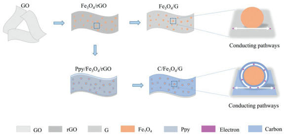
The procedure of preparing C/Fe3O4/G and Fe3O4/G is shown in Scheme 1. The GO is used as the starting material, and Fe3O4 nanoparticles are grown on GO by a hydrothermal process to give rise the Fe3O4/rGO. Post annealing is performed to transform Fe3O4/rGO into Fe3O4/G. For the preparation of C/Fe3O4/G, polypyrrole (Ppy) is coated on Fe3O4/rGO to serves as the precursor for N-carbon, which is obtained by thermal annealing in Ar atmosphere. Compared with Fe3O4/G, the C/Fe3O4/G is expected to manifest improved electrochemical performance due to the carbon-coated nanoarchitecture, which can produce highly electrical conductive pathways and cushion the volume expansion of Fe3O4 effectively in the repetitive Li-ion insertion/de-insertion procedure.

|
Download:
|
| Scheme 1. Schematic illustration of formation for Fe3O4/G and C/Fe3O4/G. | |
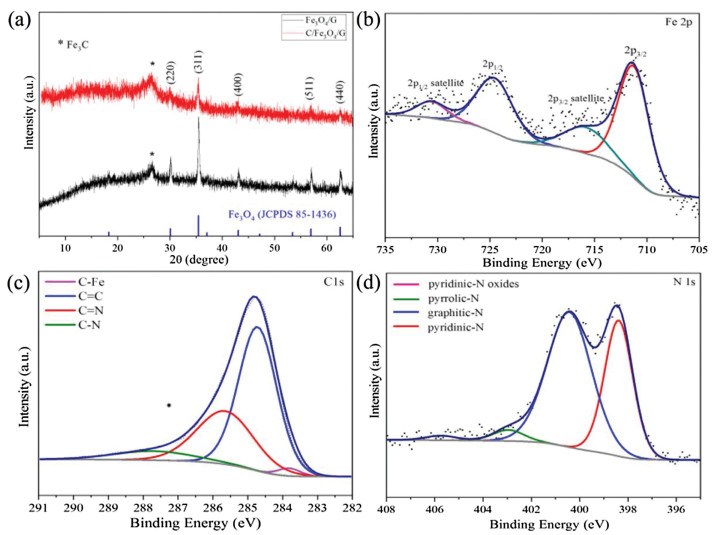
The phase structures of C/Fe3O4/G and Fe3O4/G is examined by XRD (Fig. 1a), which show similar diffraction patterns. The diffraction peak at 26.3° denotes a minor phase originated from Fe3C, which is due to carbothermal reduction of Fe3O4 to α-Fe and subsequently dissolving of the surrounding carbon atoms into the Fe lattice [19]. Other characteristic peaks are consistent with magnetite Fe3O4 (JCPDS No. 85–1436). The elemental composition is confirmed via XPS measurement. As depicted in Fig. 1b, the peaks of 711 and 725 eV correspond to Fe 2p3/2 and Fe 2p1/2 [20]. Furthermore, peaks centered at 716 and 730 eV are their satellites. Fig. 1c shows that the C 1s consists of four parts, C-Fe (283.8 eV), C=C (284.8 eV), C=N (285.6 eV) and C-N (287.6 eV) [21-23]. In Fig. 1d, the N 1s spectrum is fitted into four components of N species, i.e., pyridinic-N oxides, pyrrolic-N, graphitic-N and pyridinic-N at 405.7, 402.9, 400.5 and 398.3 eV [24], respectively. The ratio of the corresponding N species is estimated to be 1.36%, 3.31%, 58.09% and 37.24%. The high content of graphitic-N indicates the indeed doped of nitrogen in the C/Fe3O4/G composites [22]. The high ratio of pyridinic-N has been reported to improve the lithium storage performances [25].

|
Download:
|
| Fig. 1. (a) XRD pattern of Fe3O4/G and C/Fe3O4/G. XPS spectrum of (b) Fe 2p, (c) C 1s and (d) N 1s. | |
The morphology of as-prepared composites is investigated by SEM (Fig. S1 in Supporting information). Overall, both composites exhibit similar large size lamellar structure. From Figs. S1a and b, the Fe3O4 nanoparticles are uniformly loaded on the graphene sheet. However, no obvious Fe3O4 nanoparticles are observed in C/Fe3O4/G (Figs. S1c and d), which may be owing to the coverage of the carbon layers.
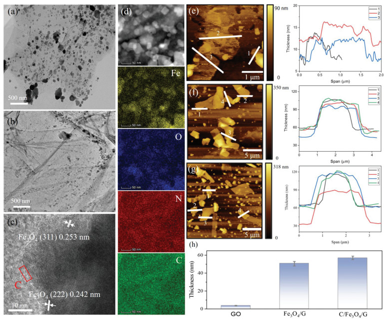
More details of morphological information are investigated by the TEM and HRTEM. From Fig. 2a, the homogeneously dispersed Fe3O4 nanoparticles on graphene display an average size of 30 nm, although some very big particle is also observed. However, for C/Fe3O4/G (Fig. 2b), the Fe3O4 nanoparticles are not obvious due to the coverage of carbon layers compared with Fe3O4/G. From the HRTEM image of C/Fe3O4/G in Fig. 2c, the (111) plane of Fe3O4 is clearly noticed with a lattice spacing of 0.48 nm, meanwhile, a carbon layer can be observed around the particle, which indicates the Fe3O4 nanoparticles are successfully loaded on the graphene and well enveloped by a thin carbon layer.

|
Download:
|
| Fig. 2. TEM images of (a) Fe3O4/G, (b) C/Fe3O4/G. (c) HRTEM image, HAADF-STEM image (d) and EDS element mapping of C/Fe3O4/G. The AFM tests of (e) GO, (f) Fe3O4/G and (g) C/Fe3O4/G. (h) The thickness comparision chart of GO, Fe3O4/G and C/Fe3O4/G. | |
Typical STEM and EDX of C/Fe3O4/G composites are shown in Fig. 2d. The STEM in Fig. 2d reveals the particle size of 20-50 nm, and elemental mapping images demonstrate the co-existence and uniform distribution of Fe, O, N and C elements. Furthermore, the carbon coating layer in C/Fe3O4/G has been proved by the AFM test. As shown in Fig. 2e, the thickness of GO is around 3.7 nm, corresponding to 3–4 layers of graphene sheets. The average thickness of Fe3O4/G is measured to be 51 nm (Fig. 2f), which is smaller than that (57 nm) of C/Fe3O4/G (Fig. 2g). Fig. 2h is the thickness comparison chart of GO, Fe3O4/G and C/Fe3O4/G, which intuitively shows the thickness change. The increased thickness of C/Fe3O4/G compared to Fe3O4/G is due to an extra layer of carbon.
Both as-prepared composites are further analyzed by the Raman spectroscopy (Fig. S2a in Supporting information). The D band at ~1350 cm-1 corresponds to the disordered structure or defects in carbon materials [26], and the G band of graphitic carbon is centered at 1587 cm-1 [27, 28]. The calculated ID/IG for C/Fe3O4/G and Fe3O4/G are both less than 1, indicating the existence of a great amount of sp2-type carbon in the materials, which will improve the electronic conductivity of the materials [29]. Compared with Fe3O4/G, the value of ID/IG of C/Fe3O4/G is higher, demonstrating that the introduction of N-carbon increases the defects which may be due to the incorporation of N atoms to eliminate the side functional groups in the GO and causes the edges disordered [30, 31].
TGA has been conducted to study the thermal stability and to determine the mass content of Fe3O4 in two as-synthesized nanocomposites. The TGA was performed in air, therefore we assume the final product is Fe2O3 from the oxidation of Fe3O4. As shown in Fig. S2b (Supporting information), the final mass content of Fe2O3 is 85.5% and 39.7% in Fe3O4/G and C/Fe3O4/G, respectively. Based on the oxidation reaction Fe3O4 + O2=6Fe2O3, the weight percentage of Fe3O4 in the two samples is calculated to be around 82.8% and 38.4%. It is obvious that the C/Fe3O4/G exhibits much higher weight loss in comparison to Fe3O4/G because of the combustion of carbon in C/Fe3O4/G. Taking the results above in consideration, the carbon layer has been successfully coated on the Fe3O4/G nanosheets. It is worth inspecting whether the N-carbon layers can contribute to an improved lithium storage performance.
The specific surface area and pore structures of C/Fe3O4/G and Fe3O4/G have been tested by N2 adsorption-desorption. The isotherms shown in Figs. S2c and d (Supporting information) reveal both samples present type-Ⅳ isotherm with an H1-type hysteresis loop, demonstrating a mesoporous structure. Mean pore diameter of C/Fe3O4/G and Fe3O4/G are about 3.935 and 3.937 nm by means of Barrett-Joyner-Halenda (BJH) tests, respectively. The BET values of C/Fe3O4/G is 125.571 m2/g, which has significantly increased compared with Fe3O4/G (47.153 m2/g). C/Fe3O4/G has higher surface area because of the coated carbon layer.
The electrochemical properties of C/Fe3O4/G and Fe3O4/G composites are first evaluated by the CV test. As illustrated in Fig. S3a (Supporting information), during the first cathodic cycle, the significant peak at 0.55 V is assigned to the formation of solid electrolyte interface (SEI) layer and electrolyte decomposition and the reduction reaction of Fe3+ and Fe2+ to Fe0 (Fe3O4 + 2Li+ + 2e-→ Li2Fe3O4 and Li2Fe3O4 + 6Li+ + 6e-→3Fe0 + 4Li2O) [32] which moves to about 0.8 V in the subsequent turns. The broad anodic peak at 1.6 V could be attributed to the oxidation of Fe0 to Fe3+ and Fe2+ (3Fe0 + 4Li2O→Fe3O4 + 8Li+ + 8e-), which moves to 1.7 V in the next curves [9]. Furthermore, the subsequent curves show a high degree of coincidence, indicating that the material has good electrochemical reversibility. For C/Fe3O4/G, the cathodic and anodic peaks intensity decreases a little after the 1st cycle, showing the occurrence of an irreversible redox reaction. On the contrary, the peak intensity and integrated area decline significantly for Fe3O4/G in Fig. S3c (Supporting information), which demonstrates a great deal of electrochemical irreversible reaction taking place in the process of lithium storage.
Figs. S3b and d (Supporting information) display galvanostatic charge-discharge curves of C/Fe3O4/G and Fe3O4/G electrodes at 100 mA/g. The C/Fe3O4/G and Fe3O4/G exhibits starting discharge/ charge capacities of 1439/899, 1112/702 (mAh/g), accounting for a Coulombic Efficiency (CE) of 62.5% and 63.1%, respectively. The low initial CE is attributed to some irreversible reactions including the formation of the SEI film [33, 34]. In addition, C/Fe3O4/G has the lower initial CE than that of Fe3O4/G which is ascribed to the higher surface area and abundant content of carbon [21, 24]. Furthermore, the capacity of Fe3O4/G and C/Fe3O4/G only has been significantly reduced in the first two cycles and then becomes quite stable.
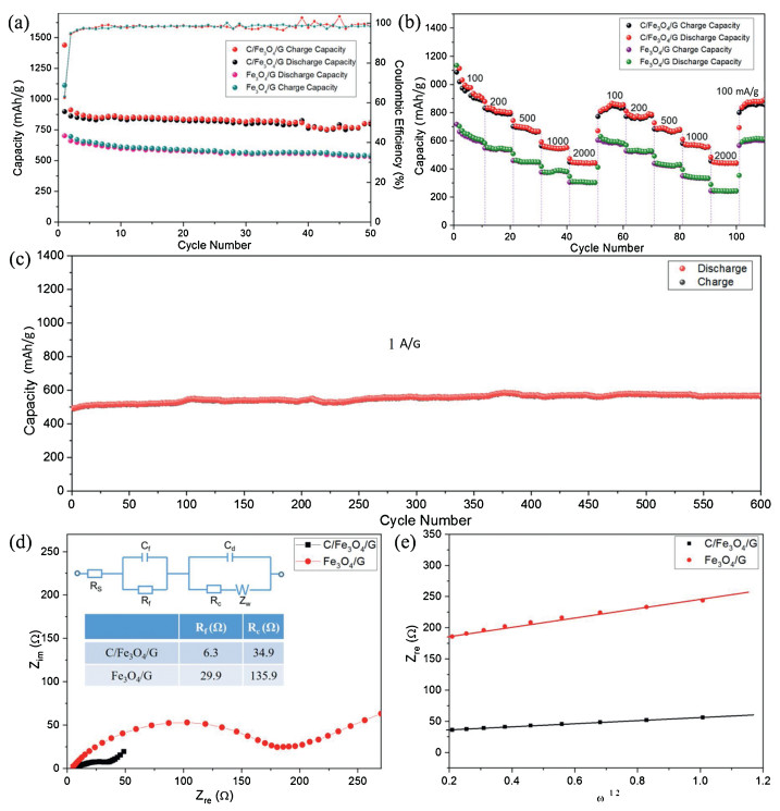
Fig. 3a compares the cycle performances of C/Fe3O4/G and Fe3O4/G electrodes at 100 mA/g. For Fe3O4/G, it delivers a high first discharge capacity of 1112 mAh/g and reduces to 540 mAh/g while the C/Fe3O4/G exhibits starting discharge capacity 1439 mAh/g and remains 807 mAh/g after 50 cycles, indicating its enhanced cycling stability. Based on the Eq. (1):

|
Download:
|
| Fig. 3. (a) Cycling performance, (b) ratecapability of C/Fe3O4/G and Fe3O4/G electrodes. (c) Long cycling performance of C/Fe3O4/G at 1 A/g (The battery for rate test was further subject to long cycling test). (d) Nyquist plot of C/Fe3O4/G and Fe3O4/G after cycling (Inset is the modified equivalent circuit). (e) Zre as the function of ω1/2. | |
|
(1) |
It can be calculated that the theoretical capacities of C/Fe3O4/G and Fe3O4/G are 584 and 828 mAh/g, respectively. The capacity of C/Fe3O4/G is higher than the theoretical capacity may due to a mixed Li-ion storage mechanism including diffusion and capacitive contribution [35, 36] and the presence of Fe3C. Fe3C can serve as a catalyst for the reversible formation/decomposition of some components in solid electrolyte interface (SEI) films in electrode and will bring extra capacity [23, 37, 38]. The capacity contribution (Cc) are calculated using Eq. (2) [39]:
|
(2) |
where C(x) is the practical theoretical capacity of C(Fe3O4), C(carbon) and C(graphene). W(x) is the mass percent of Fe3O4, carbon and graphene. C(C/Fe3O4/G) is the stable capacity of C/Fe3O4/G at the 50th cycles. According to the result of TGA, the proportion of carbon to C/Fe3O4/G is 53.62% and it can be concluded that the capacity contribution of carbon is 24.7%.
Fig. 3b displays the rate capabilities of the two electrodes at various current densities. C/Fe3O4/G can deliver stable average capacities of 950, 803, 681, 550 and 442 mAh/g at 100, 200, 500, 1000 and 2000 mA/g, respectively, while Fe3O4/G only exhibits 629, 540, 450, 380 and 304 mAh/g. As the current density returned to 100 mA/g, the reversible capacity of the C/Fe3O4/G reaches 835 mAh/g, demonstrating the superior reversibility. To further explore the C/Fe3O4/G cycling performance, the battery that was used for rate test was further tested at high current density of 1 A/g. A stable capacity of around 550 mAh/g is maintained steady after 700 cycles (Fig. 3c).
To further probe the electrode reaction kinetics of Fe3O4/G and C/Fe3O4/G, EIS measurements are carried out after 50 cycles. The Nyquist plots and fitting results are displayed in Fig. 3d, Fe3O4/G and C/Fe3O4/G display sloping line at low-frequency part and incomplete semicircle in the high-frequency part which represent the Warburg type resistance [40, 41] and Li+ diffusion procedure, respectively [42]. The corresponding semicircle diameter of the Fe3O4/G electrode is larger compared to C/Fe3O4/G. The resistance of SEI (Rf) and charge-transfer (Rc) are calculated to be 6.3 and 34.9 Ω for C/Fe3O4/G while Fe3O4/G corresponds to 29.9 and 135.9 Ω, respectively, indicating the lower charge transfer resistance related to the additional conductive carbon layer [21, 43].
Based on Eq. (3) [44], the Warburg factor (σ) is the coefficient in the linear relationship between Zre and ω-1/2, Zre is the real part of the impedance, ω is the angular frequency.
|
(3) |
According to Fig. 3e, the s of C/Fe3O4/G and Fe3O4/G are 24.92 and 72.10, respectively.
The Lithium-ion diffusion coefficient (DLi+) are expressed using Eq. (4) [21, 45]:
|
(4) |
where R is the gas constant, T is the absolute temperature, A is the contact area between the electrode and the electrolyte, n is the number of electrons transferred in the chemical reaction, F is the Faraday constant and C is the concentration of lithium ions in the electrolyte. The DLi+ of the C/Fe3O4/G (0.22 × 10⁻¹⁰ cm2/s) is higher than that of Fe3O4/G (0.26 × 10⁻¹¹ cm2/s). It indicates that the carbon increases the Li+ conduction and shortens the Li+ diffusion length [46, 47].
The above results show that enhanced cycle stability of C/Fe3O4/G is not only because of its high capacity but also because of its excellent conductivity of graphene and N-carbon. Therefore, the improved performances of C/Fe3O4/G compared to Fe3O4/G are reasonably originate from the function of N-carbon, which has good conductivity and can confine the location of Fe3O4 to prevent its agglomeration and pulverization, as well as to improve the lithium transportation kinetics.
To sum up, C/Fe3O4/G composites were synthesized by a simple hydrothermal and post-annealing procedure. Fe3O4/G interacts with N-carbon which makes C/Fe3O4/G possess good structural and phys-chemical advantages. The graphene can supports that Fe3O4 nanoparticles uniformly anchored on its surface which cooperates with carbon could effectively improveelectrical conductivity, meanwhile, relieve stress changes caused by volume expansion. Furthermore, the N-carbon layers serve a riveting layer tightly confined Fe3O4 nanoparticles to the surface of graphene, so that a much higher resistivity to material pulverization and electrode crack is obtained. Consequently, the C/Fe3O4/G delivers 807 mAh/g after 50 cycles at 0.1 A/g and even at 1 A/g, a stable capacity of 550 mAh/g after 700 cycles can still maintain. This study provides a general and reliable strategy for preparing other composites with high-performance for LIBs.
Declaration of competing interestThe authors declare that they have no known competing financial interests or personal relationships that could have appeared to influence the work reported in this paper.
AcknowledgmentsThis work is financially supported by the National Natural Science Foundation of China (Nos. 51602167, 51972182 and 61971252), Shandong Provincial Science Foundation (No. ZR2017JL021) and Key Research and Development Program (No. 2018GGX102033), and Qingdao Applied Fundamental Research Project (No. 17-1-1-81-jch) and "Distinguished Taishan Scholar" Project.
Appendix A. Supplementary dataSupplementary material related to this article can be found, in the online version, at doi: https://doi.org/10.1016/j.cclet.2020.02.006.
| [1] |
H. Ying, W.Q. Han, Adv. Sci. 4 (2017) 1700298. DOI:10.1002/advs.201700298 |
| [2] |
M. Wang, F. Zhang, C.S. Lee, Y. Tang, Adv. Energy Mater. 7 (2017) 1700536. DOI:10.1002/aenm.201700536 |
| [3] |
T. Ma, L. Sun, Q. Niu, et al., Electrochim. Acta 300 (2019) 131-137. DOI:10.1016/j.electacta.2019.01.104 |
| [4] |
Y. Zhong, M. Yang, X. Zhou, Z. Zhou, Mater. Horiz. 2 (2015) 553-566. DOI:10.1039/C5MH00136F |
| [5] |
C. Wei, H. Fei, Y. Tian, et al., Chin. Chem. Lett. 31 (2020) 980-983. DOI:10.1016/j.cclet.2019.12.033 |
| [6] |
T. Ma, X. Liu, L. Sun, et al., J. Energy Chem. 34 (2019) 43-51. DOI:10.1016/j.jechem.2018.09.017 |
| [7] |
H. Zheng, H. Zhang, Y. Fan, et al., Chin. Chem. Lett. 31 (2020) 210-216. DOI:10.1016/j.cclet.2019.03.048 |
| [8] |
Q. Wang, J. Xu, G. Shen, et al., Electrochim. Acta 297 (2019) 879-887. DOI:10.1016/j.electacta.2018.11.175 |
| [9] |
L. Su, X. Wu, L. Zheng, et al., Part. Part. Syst. Charact. 33 (2016) 597-601. DOI:10.1002/ppsc.201600053 |
| [10] |
K. Cao, T. Jin, L. Yang, L. Jiao, Materi. Chem. Front. 1 (2017) 2213-2242. DOI:10.1039/C7QM00175D |
| [11] |
J. Ye, Q. Hao, B. Liu1, Y. Li, C. Xu, Chem. Eng. J. 315 (2017) 115-123. DOI:10.1016/j.cej.2017.01.023 |
| [12] |
X. Li, Y. Hu, J. Liu, et al., Nanoscale 5 (2013) 12607-12615. DOI:10.1039/c3nr04823c |
| [13] |
J. Yin, P. Sun, G. Qu, et al., Appl. Surf. Sci. (2019) 144698. |
| [14] |
B. Xu, S. Qi, M. Jin, et al., Chin. Chem. Lett. 30 (2019) 2053-2064. DOI:10.1016/j.cclet.2019.10.028 |
| [15] |
R. Kumar, R.K. Singh, A.V. Alaferdov, S.A. Moshkalev, Electrochim. Acta 281 (2018) 78-87. DOI:10.1016/j.electacta.2018.05.157 |
| [16] |
Q. Zhao, J. Liu, Y. Wang, et al., Electrochim. Acta 262 (2018) 233-240. DOI:10.1016/j.electacta.2018.01.019 |
| [17] |
D.C. Marcano, D.V. Kosynkin, J.M. Berlin, et al., ACS Nano 4 (2010) 4806-4814. DOI:10.1021/nn1006368 |
| [18] |
J.G. Song, X.Z. Wang, C.T. Chang, J. Nanomater. 2014 (2014) 276143. |
| [19] |
J. Liu, X. Kang, X. He, et al., Nanoscale 11 (2019) 9155-9162. DOI:10.1039/C9NR01601E |
| [20] |
J. Luo, X. Xia, Y. Luo, et al., Adv. Energy Mater. 3 (2013) 737-743. DOI:10.1002/aenm.201200953 |
| [21] |
X. Chang, T. Wang, Z. Liu, et al., Nano Res. 10 (2017) 1950-1958. DOI:10.1007/s12274-016-1381-6 |
| [22] |
D. Su, M. Cortie, G. Wang, Adv. Energy Mater. 7 (2017) 1602014. DOI:10.1002/aenm.201602014 |
| [23] |
C. Guo, J.P. He, X.Y. Wu, et al., ACS Appl. Mater. Interfaces 10 (2018) 35994-36001. DOI:10.1021/acsami.8b13331 |
| [24] |
X. Liu, J. Zhang, S. Guo, N. Pinna, J. Mater. Chem. A 4 (2016) 1423-1431. DOI:10.1039/C5TA09066K |
| [25] |
Z. Yan, Q.W. Yang, Q. Wang, J. Ma, Chin. Chem. Lett. 31 (2020) 583-588. DOI:10.1016/j.cclet.2019.11.002 |
| [26] |
L. Fan, X. Li, X. Song, et al., ACS Appl. Mater. Interfaces 10 (2018) 2637-2648. DOI:10.1021/acsami.7b18195 |
| [27] |
C. Fu, G. Zhao, H. Zhang, S. Li, Int. J. Electrochem. Sci. 8 (2013) 6269-6280. |
| [28] |
Z.J. Liu, J. Yu, X.Y. Li, et al., Carbon 127 (2018) 636-642. DOI:10.1016/j.carbon.2017.11.051 |
| [29] |
S. Chen, Q. Wu, M. Wen, et al., ACS Appl. Mater. Interfaces 10 (2018) 19656-19663. DOI:10.1021/acsami.8b02839 |
| [30] |
J.J. Cai, Q.Y. Zhou, B. Liu, et al., Nanoscale 12 (2020) 973-982. DOI:10.1039/C9NR09020G |
| [31] |
Y. Hou, Z.H. Wen, S.M. Cui, et al., Adv. Funct. Mater. 25 (2015) 872-882. DOI:10.1002/adfm.201403657 |
| [32] |
C. He, S. Wu, N. Zhao, et al., ACS Nano 7 (2013) 4459-4469. DOI:10.1021/nn401059h |
| [33] |
X.H. Liu, T.T. Ma, L. Sun, et al., ChemSusChem 11 (2018) 1321-1327. DOI:10.1002/cssc.201702388 |
| [34] |
K. Cao, L. Jiao, H. Liu, et al., Adv. Energy Mater. 5 (2015) 1401421. DOI:10.1002/aenm.201401421 |
| [35] |
Y.L. An, Y. Tian, H. Wei, et al., Adv. Funct. Mater. (2019) 1908721. |
| [36] |
L. Sun, T.T. Ma, J. Zhang, et al., Electrochim. Acta 321 (2019) 134672. DOI:10.1016/j.electacta.2019.134672 |
| [37] |
L.W. Su, Y.R. Zhong, Z. Zhou, J. Mater. Chem. A 1 (2013) 15158-15166. DOI:10.1039/c3ta13233a |
| [38] |
M.Z. Zou, L.L. Wang, J.X. Li, L.H. Guan, Z.G. Huang, Electrochim. Acta 233 (2017) 85-91. DOI:10.1016/j.electacta.2017.02.079 |
| [39] |
W. Xin, T. Gao, W. Zhang, et al., J. Alloys. Compd. 784 (2019) 157-164. DOI:10.1016/j.jallcom.2019.01.038 |
| [40] |
Q. Hao, J. Wang, C. Xu, J. Mater, Chem. A 2 (2014) 87-93. |
| [41] |
C. Xu, Q. Hao, D. Zhao, Nano Res. 9 (2016) 908-916. DOI:10.1007/s12274-015-0973-x |
| [42] |
M. Mao, F. Yan, C. Cui, et al., Nano Lett. 17 (2017) 3830-3836. DOI:10.1021/acs.nanolett.7b01152 |
| [43] |
T. Ma, X. Liu, L. Sun, et al., Electrochim. Acta 293 (2019) 432-43814. DOI:10.1016/j.electacta.2018.10.066 |
| [44] |
L. Sun, X. Liu, T. Ma, et al., Solid State Ion. 329 (2019) 8-14. DOI:10.1016/j.ssi.2018.11.001 |
| [45] |
X. Wang, H. Hao, J. Liu, T. Huang, A. Yu, Electrochim. Acta 56 (2011) 4065-4069. DOI:10.1016/j.electacta.2010.12.108 |
| [46] |
J. Sun, C. Lv, F. Lv, et al., ACS Nano 11 (2017) 6186-6193. DOI:10.1021/acsnano.7b02275 |
| [47] |
J.G. Wang, H. Sun, H. Liu, et al., ACS Appl. Mater. Interfaces 10 (2018) 13581-13587. DOI:10.1021/acsami.8b02111 |