 2020, Vol. 31


As science and technology advance, the crisis of energy and environmental pollution is increasingly serious. Then electrochemical water splitting came into being, which is considered as the potential technology to produce clean and renewable energy [1-10]. However, oxygen evolution reaction (OER) is considered to be a major obstacle to overall water splitting due to its sluggish kinetics [11-16]. Thus, it is of great significance to develop high-efficient electrocatalysts to reduce high overpotentials and accelerate OER reactions [17-22].Up tonow, IrO2 and RuO2 preciousmetalmaterials have been regarded as the most advanced catalysts for the OER [23-26]. Nevertheless, high cost and scarcity tremendously restrict their practical application.
In the past several decades, a host of efforts has been devoted to search for low cost and high efficiency OER catalysts to replace precious metal materials. One effective way to improve the catalytic performance is the introduction of sulfide or phosphide with a transition metal, achieving more active sites with synergistic interactions. Both experimental and theoretical researchers have proved that transition metal phosphides (TMPs) exhibited efficient electrocatalytic performance for OER [27-29]. As part of TMPs, cobalt phosphide (CoP) is considered as a promising catalyst for its high electrical conductivity, but its application is limited by its defects such as easy agglomeration and instability [16, 17, 30-32]. Yang et al. ever develop a way to assemble the CoP nanoparticles on the surface of carbon material, which could deal with the problem of its easy agglomeration, corrosion and unstable [29]. Therefore, it is a novel idea for us to design and synthesize an easy to separate and recyclable catalyst with good stability and dispersity. Meanwhile, silica has crystalline and amorphous forms and its chemical properties are relatively stable. As is known to all that the encapsulation method has the merit of avoiding the aggregation of nanoparticles during the process of reaction [33-37]. Nanoreactor is an ideal nanoparticle dispersion matrix, which can effectively solve the problem of aggregation and achieve a relatively stable state [38-44].
In this paper, we firstly synthesized CoP nanoparticles encapsulated in porous silica shell (SiO2) as electrocatalyst for OER in lye. Based on our previous work [45], the successfully synthesized Co3O4@SiO2 was used as a precursor to provide reaction site for phosphating reaction. This porous and hollow structure could (1) inhibit nanoparticles aggregation defects, thereby providing more active sites and significantly improving the efficiency of charge transfer, (2) produce homogeneous heterogenous interfaces to reduce effect of the phase interface and (3) promote the electrolyte diffusing completely to the electrode. Moreover, we investigated the influence of different phosphating degrees on electrochemical catalytic performance and considered different phosphating degrees through changing the amount of NaH2PO2. The obtained CoP@SiO2 (CP3) displays outstanding catalytic activity to the OER, proving a low overpotential of 280 mV at a current density of 10 mA/cm2 under alkaline condition and a Tafel value of 89 mV/dec and keeping chemical stability for 12000s. Such excellent electrochemical performance can be benefiting from the stable and porous silicon shell, which ensures fast charge transfer in the electrocatalyst. It is noteworthy that the direct active site for catalysis not locate on the shell surface but on the surface of the CoP. Moreover, the encapsulated CoP particles avoid large-scale agglomeration and corrosion and provide a large number of effective active sites with synergistic effect. Most importantly, the low-cost and simple synthetic method is available in the actual production of hollow nanocatalysts for OER, thus making a crucial contribution to electrocatalytic water splitting.
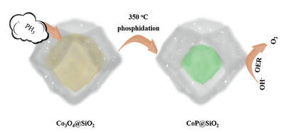
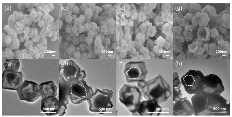
The simple synthesis of CoP@SiO2 was illustrated in Fig. 1. The Co3O4@SiO2 and NaH2PO2 were placed at both ends of the porcelain boat for calcination. As the temperature increases, the concomitant PH3 gas released by heat decomposition of NaH2PO2 passed through the porous silicon shell and entered the shell together with the airflow, and reacted with Co3O4 to obtain CoP. When the quality ratios of Co3O4@SiO2 and NaH2PO2 were 10 mg:100 mg, 10 mg:200 mg and 10 mg:500 mg, the obtained products were denoted as CP1, CP2 and CP3. The porous structure can offer a larger electrode-electrolyte contact area and a large number of active sites, greatly shortening the ion diffusion distance [46]. These composite materials are generally considered to possess high porosity with excellent electrical conductivity and outstanding mechanical stability [47, 48]. SEM and TEM characterization are used to examine the internal, external structural features and morphologies of the synthesized samples. Fig. 2a shows the morphology of the Co3O4@SiO2 sample, it is observed that precursor is a dodecahedron with smooth surface. Subsequently, the TEM image in Fig. 2b clearly displays that the precursor is a core-shell structure. After phosphating, the surface morphology of the sample did not change much, and the shape of dodecahedron was still maintained. With the increase of the phosphating degree, the protective effect of silicon shell still works. Figs. 2c, e and g show the morphology of CP1, CP2, CP3, it is clearly that the amount of NaH2PO2 has no significant influence on the morphology. More detailed information about the microstructure and morphology of the CP1, CP2, CP3 samples are investigated by TEM and HRTEM. As can be seen from Figs. 2d, f and h, CoP core is well preserved in silicon dioxide shell, further confirming the stability and uniqueness of this core-shell structure. To observe the structural features intuitively, we have marked the CoP core. However, the CoP core is far smaller than the Co3O4 core at the same nanoscale. This result proves that the particle agglomeration of CoP is more serious than that of Co3O4. At the same time, the second function of the silicon shell was verified, that is, it effectively inhibits the large-area agglomeration of nanoparticles and ensures certain active sites, which also explained the importance of choosing Co3O4@SiO2 with the core shell structure as the precursor. The HRTEM image and SAED pattern of the CP3 are respectively exhibited in Figs. S1a and b (Supporting information). The uniformly arranged lattice fringes in the Figs. 1b correspond to the lattice planes of the CoP, whereas where the lattice fringes are not visible is due to the presence of amorphous silica. Due to the CoP is covered by the silicon shell, we found the thin silicon shell and captured the lattice fringe of the core. The structure and polycrystalline properties of spinel can be well indicated by diffraction ring in SAED patterns. Additionally, the elemental mapping pictures demonstrate the uniform distribution of Co, O, Si and P throughout the CP3 (Fig. S1c in Supporting information). From the X-ray diffraction (Fig. S2 in Supporting information) of the CP series, we can confirm that the peak of the sample tends to be flat, which is influenced by amorphous silicon shell material. Many local defects may occur in amorphous materials, which may expose more active sites and improve the activity of catalytic reactions. The XRD patterns of Co3O4@SiO2 are consistent with previous reports, proving the successful synthesis of the precursor. Compared with the peak shape of Co3O4@SiO2, CP series samples change significantly, but the trend of curves do not change too much, which was attributed to partial phosphating inside the core-shell structure. Fig. S3 (Supporting information) shows the diffraction peaks of CP3 samples corresponding to the CoP (JCPDS No. 29-0497) and SiO2 (JCPDS No. 47-1144). In addition, these curves exhibit that CP1, CP2, CP3 are identical substances. The FT-IR spectra of the Co3O4@SiO2, CP1, CP2, CP3 are analyzed, and the results show that the samples have the similar molecular structure except for slight differences in Co3O4@SiO2. The samples display peaks around 1600 cm-1 correspond to bending vibration of H-O-H bond, proving the existence of interstitial water in these compounds. The wide absorption at around 1100 cm-1 is the anti-symmetric stretching vibration of Si-O-Si. (Fig. S4 in Supporting information)

|
Download:
|
| Fig. 1. Schematic illustration of the synthesis of CoP@SiO2 catalysts. | |

|
Download:
|
| Fig. 2. SEM and TEM images of the (a, b) Co3O4@SiO2, (c, d) CP1, (e, f) CP2, (g, h) CP3. | |
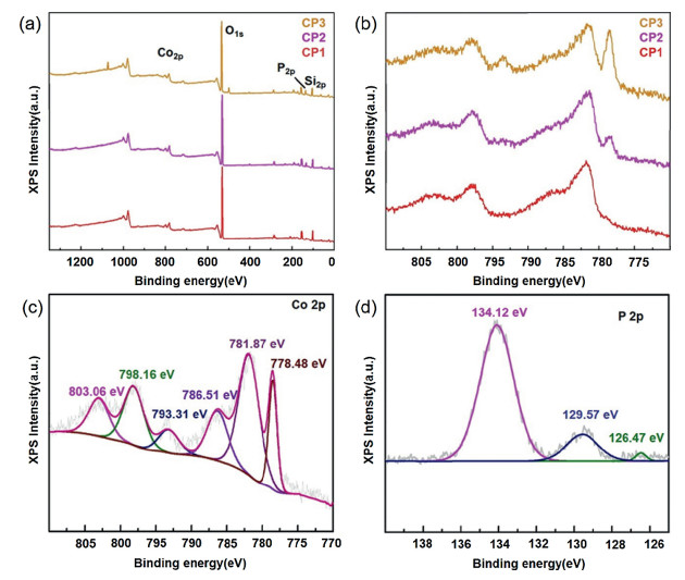
The surface composition and chemical state of the CP series samples are conducted by X-ray photoelectron spectroscopy (XPS). In Fig. 3a, the Co, P, O and Si elements can be distinguished through the peaks of Co 2p, O 1s, P 2p and Si 2p, the result is correspond to the elemental mapping in Fig. S1. Fig. 3b shows the Co 2p spectrum of the CP serie materials, the peak around 778 eV is increasingly prominent with the deepening of phosphating degree. As exhibited in the Fig. 3c, two peaks respectively locate at 781.87 eV and 798.16 eV are correspond to Co 2p3/2 and Co 2p1/2, which are all due to oxidized Co species. Additionally, three main peaks occurred in P 2p region at 134.12 eV, 129.57 eV and 126.47 eV are assigned to oxidized P species, P 2p1/2 and P 2p3/2. (Fig. 3d) According to the appearance of peaks at 781.87 eV and 134.12 eV, it can be inferred that oxygen species existed on surface of CoP. Two peaks located at 778.48 eV and 126.47 eV in CP3 are attributed to the Co-P binding. In general, the CP series samples are composed of CoP and SiO2, which serve as the main active sites in electro-oxidation reaction process. Highly conductive metal phosphides promote electron transfer and boost the kinetics of OER in water oxidation.

|
Download:
|
| Fig. 3. (a) XPS survey spectra of the CP series materials, (b) The Co 2p spectra of the CP series materials, (c) The Co 2p and (d) P 2p spectra of CP3. | |
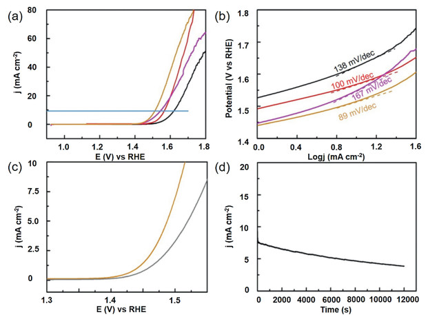
The samples were tested with a three-electrode system in N2- saturated 1 mol/L KOH solution to evaluate the electrolytic water activity of the electrocatalyst. Fig. 4a shows the linear scanning voltammetry (LSV) polarization plot of sample supported on glassy carbon electrode (GCE). It is well known that the work potential of 10 mA/cm2 is an indispensable parameter to evaluate OER performance, the voltage of CP3 catalystis1.51 V at10 mA/cm2. The value is far lower than that of Co3O4@SiO2 (1.62 V), CP1 (1.57 V) and CP2 (1.54 V), indicating the CP3 catalyst possess a better catalytic activity and oxygen evolution performance. Moreover, the CP3 electrode delivers an overpotential of 280 mV at the current density of 10 mA/cm2, the result is much lower than Co3O4@SiO2, CP1 and CP2 thatcorrespondto392 mV, 337 mVand315 mV.ItisobviousthatCP3 shows prominent catalytic activity compared with cobalt-based oxide materials and homologous substances with low phosphating degree. In a word, the optimized electronic structure reduces the kinetic energy barrier of catalytic reaction. Fig. 4b depicts the Tafel diagram of the samples constructed based on the polarization curve. A lower Tafel value tend to reflect an exceedingly rapid electron transport and catalytic rate. The Tafel slope of the CP3 (89 mV/dec) is farlowerthanthoseobservedforCP1 (94 mV/dec), CP2 (167 mV/dec) and Co3O4@SiO2 (138 mV/dec), which demonstrate the excellent kinetic of CP3 catalyst during oxygen evolution process. The redox reaction mechanism of CoP and the relative electro-chemical reaction are provided as follows [25]:

|
Download:
|
| Fig. 4. (a) LSV curves for the OER in 1.0 mol/L KOH electrolyte at 5 mV/s and (b) Tafel slopes of CS2, CP1, CP2, CP3 (orange means CP3; magenta means CP2; red means CP1; black means Co3O4@SiO2). (c) Durability test for the CP3 for 1000 cycles and (d) chronoamperometric testing of CP3 for 12, 000 s in 1.0 mol/L KOH electrolyte. | |

|
The electro-chemical double layer capacitance (Cdl) is a general parameter representing electrochemical surface areas. As shown in Figs. S6-S8 (Supporting information), the Cdl value of CP3 is 36.5 mF/cm2, which is greatly exceeding CP1 (16.2 mF/cm2) and CP2 (20.2 mF/cm2). The value is larger, the surface of the electrode is rougher and more active sites are exposed, suggesting that CP3 nanomaterials with higher phosphating degree promote more to the evolution of OER. In order to further prove the catalytic ability of CP3, the precursors and CP series products were analyzed by electrochemical impedance spectroscopy (EIS) with one GCE, as displayed in Fig. S5 (Supporting information). Compared with other cobalt-based samples, CP3 nanoparticles show smaller charge transfer resistance, which indicates that CP3 catalysts possess faster electron transfer speed and higher electric conductivity in the electrochemical OER process. In addition, the corresponding electrode possesses an excellent conductivity, thus it is beneficial to decrease the overpotential of the redox process and enhance oxygen production performance effectively. The durability of the synthesized samples is critical for the development of electro-catalysts in energy converse and storage devices. Fig. 4c exhibits the LSV polarization plots of the CP3 sample before and after 1000 cycles. After 1000 cycles, the catalytic activity of the CP3 modified electrode decreased slightly in comparison with the initial cycle, indicating that the electrode materials still maintain certain catalytic activity. Moreover, we also finish a potentiostatic plot under the same conditions exhibited in Fig. 4d. As can be seen from the i-t plot, the catalytic current density decreases slightly through the continuous operation of 12, 000 s, which can be ascribed to the catalysts shedding of the working electrode in the test process. After 12, 000 s of stability, negligible changes in the SEM were observed, the materials still maintain original morphology. (Fig. S9 in Supporting information) This result is consistent with the above description and further proves that the CP3 modified electrode possess satisfactory chemical stability. In a nutshell, the research suggests that silicon-clad metal phosphide nanoreactors may be a promising catalytic material in future life due to their easy availability and low cost, thus replacing noble metal oxides for practical electrochemical applications.
To sum up, our work shows a simple calcination method to synthesize CoP@SiO2 nanoreactors, which serves as highly efficient catalysts for the OER. Precursors provide an appropriate react space and play an important role in controlling the size and even the morphology of cobalt phosphide nanoparticles. Above chemical characterization suggests that the success of phosphating results in more merits in electrocatalytic oxygen production, including more active sites, faster charge transfer and higher catalytic efficiency. The exceptional electrocatalytic performance of CP3 is primarily ascribed to its special pore structure. Nanomaterials with microporous structure possess outstanding electrocatalytic reaction rate, which could effectively weaken the resistance between the electrolyte and catalysts, so as to accelerate the oxygen releasing. The CP3 sample exhibits a low overpotential of 280 mV and a small Tafel value 89 mV/dec, better than other cobalt-based catalysts. However, we need to further enhance the chemical stability of samples through combining CoP with graphene or highly conductive materials. In the coming future, the synthetic method could be widely applied in the research and development of high efficiency and low cost electrocatalysts with different microporous structures. The synthesized product provides novel insight for designing the new catalysts and paving the way for the study of energy materials in diverse fields of electrochemistry.
Declaration of competing interestThere are no economic and financial disputes among the authors.
AcknowledgmentsThis work was supported by the National Natural Science Foundation of China (Nos. U1904215, 21671170 and 21673203), the Top-notch Academic Programs Project of Jiangsu Higher Education Institutions (TAPP), Program for New Century Excellent Talents of the University in China (No.NCET-13-0645), the Six Talent Plan (No. 2015- XCL-030), Qinglan Project of Jiangsu, Program for Colleges Natural Science Research in Jiangsu Province (No.18KJB150036) as well as the Science and Technology Innovation Foster Foundation of Yangzhou University (No. 2016CXJ010). We also acknowledge the Priority Academic Program Development of Jiangsu Higher Education Institutions and the technical support we received at the Testing Center of Yangzhou University.
Appendix A. Supplementary dataSupplementarymaterial related to this article canbefound, in the online version, at doi:https://doi.org/10.1016/j.cclet.2020.03.041.
| [1] |
S. Cao, S. Zheng, H. Pang, Microchim. Acta 187 (2020) 168. DOI:10.1007/s00604-020-4153-7 |
| [2] |
D. Ma, C. Cao, X. Li, J. Cheng, L. Zhou, Electrochim. Acta 321 (2019) 134679. DOI:10.1016/j.electacta.2019.134679 |
| [3] |
Z. Liang, R. Zhao, T. Qiu, R. Zou, Q. Xu, Energy Chem. 1 (2019) 100001. DOI:10.1016/j.enchem.2019.100001 |
| [4] |
Y. Ni, B. He, S. Luo, et al., Appl. Catal. B. Environ. 259 (2019) 118091. DOI:10.1016/j.apcatb.2019.118091 |
| [5] |
Y. Xu, Q. Li, H. Xue, H. Pang, Coord. Chem. Rev. 376 (2018) 292. DOI:10.1016/j.ccr.2018.08.010 |
| [6] |
J. Ma, J. Wen, Q. Li, Q. Zhang, Int. J. Hydrogen Energy 38 (2013) 14896-14902. DOI:10.1016/j.ijhydene.2013.09.046 |
| [7] |
Y. Li, Y. Shan, H. Pang, Chin. Chem. Lett. (2020). DOI:10.1016/j.cclet.2020.03.027 |
| [8] |
M. Zhong, D. Yang, C. Xie, et al., Small 12 (2016) 5564-5571. DOI:10.1002/smll.201601959 |
| [9] |
Q. Li, Y. Xu, S. Zheng, et al., Small 14 (2018) 1800426. DOI:10.1002/smll.201800426 |
| [10] |
X. Guo, G. Zhang, Q. Li, H. Xue, H. Pang, Energy Storage Mater. 15 (2018) 171-201. DOI:10.1016/j.ensm.2018.04.002 |
| [11] |
Y. Zhao, L. Wang, N.N. Fan, et al., Cryst. Growth Des. 18 (2018) 7114-7121. DOI:10.1021/acs.cgd.8b01290 |
| [12] |
K.E. Ramohlola, G.R. Monana, M.J. Hato, et al., Compos. Part. B. Eng. 137 (2018) 129-139. DOI:10.1016/j.compositesb.2017.11.016 |
| [13] |
Y. Zhao, X.G. Yang, X.M. Lu, et al., Inorg. Chem. 58 (2019) 6215-6221. DOI:10.1021/acs.inorgchem.9b00450 |
| [14] |
W. Chen, J. Pei, C.T. He, et al., Adv. Mater. 30 (2018) 1800396. DOI:10.1002/adma.201800396 |
| [15] |
H. Jia, Y. Yao, J. Zhao, et al., J. Mater. Chem. A 6 (2018) 1188-1195. DOI:10.1039/C7TA07978H |
| [16] |
C. Gu, J. Li, G. Yang, et al., Chin. Chem. Lett. (2020). DOI:10.1016/j.cclet.2020.02.044 |
| [17] |
Y. Pan, K. Sun, S. Liu, et al., J. Am. Chem. Soc. 140 (2018) 2610-2618. DOI:10.1021/jacs.7b12420 |
| [18] |
M. Zhang, C. Wang, C. Liu, et al., J. Mater. Chem. A 6 (2018) 11226-11235. DOI:10.1039/C8TA03565B |
| [19] |
G. Cai, W. Zhang, L. Jiao, S.-H. Yu, H.-L. Jiang, Chem 2 (2017) 791-802. DOI:10.1016/j.chempr.2017.04.016 |
| [20] |
C. Du, X. Gao, C. Cheng, et al., Electrochim. Acta 266 (2018) 348-356. DOI:10.1016/j.electacta.2018.02.035 |
| [21] |
G. Xu, G.C. Xu, J.J. Ban, et al., J. Colloid Interface Sci. 521 (2018) 141-149. DOI:10.1016/j.jcis.2018.03.036 |
| [22] |
F. Yang, P. Zhao, X. Hua, et al., J. Mater. Chem. A 4 (2016) 16057-16063. DOI:10.1039/C6TA05829A |
| [23] |
W. Zhang, G. Lu, C. Cui, et al., Adv. Mater. 26 (2014) 4056-4060. DOI:10.1002/adma.201400620 |
| [24] |
D. Shi, R. Zheng, M.J. Sun, et al., Angew. Chem. Int. Ed. 56 (2017) 14637-14641. DOI:10.1002/anie.201709869 |
| [25] |
X. Zhang, A. Wu, X. Wang, et al., J. Mater. Chem. A 6 (2018) 17905-17914. DOI:10.1039/C8TA05551C |
| [26] |
D. Li, H.Q. Xu, L. Jiao, H.L. Jiang, Energy Chem. 1 (2019) 100005. DOI:10.1016/j.enchem.2019.100005 |
| [27] |
D.M. Chen, N.N. Zhang, J.Y. Tian, C.S. Liu, M. Du, J. Mater. Chem. A 5 (2017) 4861-4867. DOI:10.1039/C6TA10785K |
| [28] |
C.S. Liu, Z.H. Zhang, M. Chen, et al., Chem. Commun. 53 (2017) 3941-3944. DOI:10.1039/C7CC00029D |
| [29] |
S. Yang, L. Chen, W. Wei, X. Lv, J. Xie, Appl. Surf. Sci. 476 (2019) 749-756. DOI:10.1016/j.apsusc.2019.01.131 |
| [30] |
L. Yang, M. Huang, M. Lu, et al., Chem. Eng. J. 364 (2019) 462-474. DOI:10.1016/j.cej.2019.01.107 |
| [31] |
X. Xiao, Q. Li, X. Yuan, et al., Small Methods 2 (2018) 1800240. DOI:10.1002/smtd.201800240 |
| [32] |
Q. Zong, H. Yang, Q. Wang, et al., Dalton Trans. 47 (2018) 16320-16328. DOI:10.1039/C8DT03755H |
| [33] |
W. Liu, J. Huang, Q. Yang, et al., Angew. Chem. Int. Ed. 56 (2017) 5512-5516. DOI:10.1002/anie.201701604 |
| [34] |
Q. Wang, Z.Q. Liu, X.Y. Zhang, et al., J. Mater. Chem. A 5 (2017) 9523-9527. DOI:10.1039/C7TA01910F |
| [35] |
J. Peng, X. Sun, Y. Li, et al., Microporous Mesoporous Mater. 268 (2018) 268-275. DOI:10.1016/j.micromeso.2018.04.005 |
| [36] |
C.S. Liu, J. Li, H. Pang, Coord. Chem. Rev. 410 (2020) 213222. DOI:10.1016/j.ccr.2020.213222 |
| [37] |
Y. Liu, H. Wang, K. Yang, et al., Appl. Sci. -Basel 9 (2019) 2677. DOI:10.3390/app9132677 |
| [38] |
Q. Wang, Z.Q. Liu, H.Y. Zhao, et al., J. Mater. Chem. A 6 (2018) 18720-18727. DOI:10.1039/C8TA06491A |
| [39] |
M. Li, D. Liu, M. Hao, et al., Appl. Surf. Sci. 479 (2019) 77-85. DOI:10.1016/j.apsusc.2019.01.245 |
| [40] |
N. Sui, R. Yue, Y. Wang, et al., J. Alloys. Compd. 790 (2019) 792-798. DOI:10.1016/j.jallcom.2019.03.196 |
| [41] |
J. Xu, Y. Wang, S. Cao, et al., J. Mater. Chem. A 6 (2018) 17329. DOI:10.1039/C8TA05976D |
| [42] |
X. Li, X. Yang, H. Xue, H. Pang, Q. Xu, Energy Chem. 2 (2020) 100027. DOI:10.1016/j.enchem.2020.100027 |
| [43] |
X.B. Meng, J.L. Sheng, H.L. Tang, et al., Appl. Catal. B:Environ. 244 (2019) 340-346. DOI:10.1016/j.apcatb.2018.11.018 |
| [44] |
G. Huang, D.M. Yin, L.M. Wang, J. Mater. Chem. A 4 (2016) 15106-15116. DOI:10.1039/C6TA05389K |
| [45] |
L. Jin, X. Li, C. Liu, H. Pang, Chin. Chem. Lett. (2020). DOI:10.1016/j.cclet.2019.08.044 |
| [46] |
Y. Wang, H. Jia, Y. Yao, et al., J. Mater. Chem. A 6 (2018) 1188-1195. DOI:10.1039/C7TA07978H |
| [47] |
H.B. Wu, B.Y. Guan, P. He, X.Y. Yu, J. Mater. Chem. A 6 (2018) 19338-19341. DOI:10.1039/C8TA07080F |
| [48] |
K.B. Wang, Q. Xun, Q. Zhang, Energy Chem. 2 (2020) 100025. DOI:10.1016/j.enchem.2019.100025 |