 2020, Vol. 31


b Laboratory of Clean Energy Chemistry and Materials, State Key Laboratory of Solid Lubrication, Lanzhou Institute of Chemical Physics, Chinese Academy of Sciences, Lanzhou 730000, China;
c College of Physical Science and Technology, Lanzhou University, Lanzhou 730000, China
With the rapid development of world economy, the unprecedented challenges including the fossil fuels crisis and the environment pollution are becoming more and more serious. It is urgent to look for large-scale clean and sustainable energy sources. Electrochemical energy storage devices as an important clean energy system have drawn tremendous attention [1]. Among them, two complementary electrical energy storage, lithium-ion batteries (LIBs) and supercapacitors (SCs), are recognized as two promising systems. LIBs show competitive superiority in energy density up to 150–200 Wh/kg, but suffer from unsatisfactory power density less than 0.5 kW/kg, because of faradaic reactions controlled by sluggish ion diffusion during the charging/discharging process. Thus, LIBs cannot satisfy the maximum peak power required, when they used as electrical energy storage alone [2-5]. Conversely, SCs store charges in the form of interfacial double layer, their energy storage behavior is a surface control process, which have prominent power density (as high as 10 kW/kg), long cycle life (more than 105 cycles), but low energy density (less than 5 Wh/kg) [6, 7]. Therefore, it is highly desired to develop an electrochemical energy storage device to combine the merits of LIBs and SCs, which can show both high energy and power density.
Since 2001, the research on the combination of SCs and LIBs has gradually emerged, that is added capacitor-type electrode materials in lithium ion battery [8], combining the advantages of the SCs and LIBs and building lithium ion hybirid capacitor (LIHCs), which can effectively expand the voltage window of the SCs without loss of capacitance and improve the energy density. Therefore, LIHCs can overcome the insufficient energy density of SCs and the sluggish charge/discharge rates of LIBs [9], and have attracted wide attention from scientific and commercial circles [10-12]. Due to LIHCs use a battery-type anode (faradic) and a capacitor-type cathode (non-faradic) in one device, the energy storage dynamic performance of the battery-type anode is quite different from the capacitor-type cathode, and the specific capacity of the capacitortype cathode is much lower than battery-type anode, which makes it difficult for battery-type anode and capacitor-type cathode play a good role in coordination and enhancement. Thus, developing high matching electrode materials remain challenge for high performance LIHCs [13, 14].
LIHCs generally choose activated carbons as cathode because of these high specific surface area (SSA) and good electrical conductivity, expecting used as high-specific-capacitance cathode materials to match the high specific capacity of anode materials and have been widely studied [15, 16]. For example, Yan and coworkers have been made great efforts to explore high-performance hybrid capacitors and reported a series of carbon based cathode materials including porous carbon and 3D framework carbon [12, 17, 18]. Among them, the porous carbon (APDC) material shows an excellent performance have been widely used as cathode for LIHCs.
In fact, most research on LIHCs has focused on anode materials [19-21]. Among them, graphite [22], silicon [23], hard carbon [24, 25], lithium titanate [8], transition metal oxides/hydroxides [13], graphene composites [26, 27], porous carbon [28, 29] are widely recognized as the potential anode materials in LIHCs due to their large theoretical capacities (150–2000 mAh/g) [20, 21]. However, most anodes materials have sluggish redox kinetics, that is difficult to match the charge/discharge rate of capacitortype cathode materials. Currently, carbonaceous materials as anode electrode materials used in LIHCs alleviate the poor dynamic matching between the two electrodes be widely attention [24, 30]. Moreover, pre-lithiumed carbon materials reached a relatively low potential (close to 0.1 V vs. Li/Li+), achieve a high operating potential and a high energy density of LIHCs [31-33]. Thus, great efforts have been made to research carbonaceous materials including graphene [34], hard carbon [35], carbon nanotubes (CNTs) [36], porous carbon [37], and three-dimensional carbon frameworks [38]. The performance of carbonaceous materials have been greatly improved. In particular, heteroatom doped carbonaceous materials shows excellent performance, Among them, the Ndoping is considered to be an effective method to improve rate and capacity of carbonaceous anode materials [35, 38, 39]. because it can drastically improve the electrical conductivity and the surface wettability, which benefited for decrease the charge transfer resistance, create active size for Li ion storage and improve the Li ion storage kinetic effectively [40]. B and N dual-doped 3D carbon nanofbers prepared by Yu and co-workers show a high performance in LIHCs [38]. Vanadium nitride on graphene constructed by Yan et al., exhibiting a large Li-ion storage capacity and the fast charge/discharge rate [17]. Liu et al. also developed a nitrogen doped carbonized bacterial cellulose (CBC-N) nanofibers by onestep carbonization of polyaniline coated bacterial cellulose (BC) nanofibers that display excellent capacitive performance [35]. Further researchs indicated that increasing N-doping level is very important for high-performance. the work of Ren et al. achieve 15.8 at% in 3D graphene networks and shows excellent performance in Supercapacitors [41]. However, the N atom level always less than 3 at% for ordered pure carbon materials due to its perfect crystal lattice without too much defects and vacancies [42, 43]. Therefore, the preparation technology of high level N-doping doped carbonaceous materials is still widely needed.
Recently, we develop and synthesize a N-doping carbon nanotubes encapsulated cobalt nanoparticles (Co@NCNTs) via a facile multistep pyrolysis method as a low-cost dual-functional catalyst, which show the excellent activity and high stability for the ODH and CTH reactions [44]. The Co@NCNTs prepared by this method not only keep relatively high-level N-doping, but also remained a larger mumber oxygen groups form an amorphous structure. That is an ideal structure as anode for LIHCs due to N doped facilitate the charge transfer and create active size for Li ion accommodation, and the oxygen groups through redox reactions increase energy storage. Then considering Co NPs has no capacity contribution, removing the Co NPs and opening the port of Co@NCNTs, an NCNTs we prepared showed good performance. Furthermore, based on the good matching characteristics in electrochemical properties use APDC as cathode, and fabricated a novel NCNTs//APDC hybrid capacitor. It shows the excellent properties among the current LIHCs with respect to high energy these high specific surface area (SSA) and good electrical conductivity, expecting used as high-specific-capacitance cathode density of 173 Wh/kg at 200 W/kg and still reached 53 Wh/kg at a high power density of 10 kW/kg as well as outstanding cyclic life (80% capacity retention after 5000 cycles tested at 1.0 A/g within 0–4.0 V).
Preparation of NCNTs: We use a multistep pyrolysis method to prepare NCNTs. Briefly, the NCNTs anode is derived from Co@NCNTs, which reported in our previous work [44]. 22 mg Co (acac)2 was dissolved in 2 mL benzene and 1 g C2H4N4 was dispersed in 2 mL benzene, followed by the vigorous stirring for 12 h at room temperature. After filtratting and vacuum drying, the mixture was grinded in pink powder. Then, the as-obtained powder was followed heating at 350 ℃ for 3 h, at 650 ℃ for 3 h and at 700 ℃ for 2 h under Ar atmosphere gradually with a heating rate of 5 ℃/min. The obtained annealed product donated as Co@NCNTs can be used as catalyst have been confirmed [44]. Subsequently, treating Co@NCNTs with acided solution (volume of HNO3: HCl = 1:3) to remove Co NPs and washed with deionized water for several times. Finally, the powder of NCNTs is collected after vacuum drying overnight.
Preparation of APDC: APDC was synthesized by high-temperature carbonization of polyaniline followed by the KOH activation based on Yan and co-workers' works [12, 18]. Briefly, the prepared polyaniline (PANi) nanorods were used as precursors to prepare polyaniline carbonate (PDC) by pyrolysis at 800 ℃ under Ar atmosphere for 1 h. Subsequently, 0.5 g PDC was mixture with 3 g KOH, and then heated at 800 ℃ for 1 h under Ar atmosphere. The as-obtained powder was washed with 1 mol/L HCl solution and deionized water for several times until pH 7. The samples were dried at 60 ℃ overnight in an oven.
The structure was investigated by powder X-ray diffraction (XRD, Cu Kα radiation, Panalytical X'Pert Pro) and Raman spectroscope (JY-HR800, the excitation wavelength of 532 nm). The microstructure and morphology were characterized by scanning electron microscopy (SEM, JSM 6701 F) and transmission electron microscopy (TEM, TecnaiF20, 200 kV). The surface chemical compositions were examined by X-ray photoelectron spectroscopy (XPS, Perkin–Elmer PHI-5702) with a 1486.6 eV radiation as the excitation source. The distribution of pore size and specific surface area (SSA) were characterized by BrunauerEmmett-Teller (BET, Micrometrics ASAP 2020).
Fabrication of NCNTs anode electrode: Anode electrode was prepared by mixing the active material NCNTs, conducting filler (acetylene black) and binder (40 mg/mL polyvinylidene difluoride (PVDF)) with weight ratio of 80:10:10 using N-methyl-2-pyrrolidone (NMP) as dispersion, and then coated the homogeneous slurry onto a copper foil and dried under vacuum at 110 ℃ for 10 h. The loading mass of the active material was about 0.8~1.0 mg/cm2. After that, the anode electrodes were transferred into in an argonfilled glove box.
Fabrication of APDC cathode electrode: Cathode electrode was prepared by mixing the active material APDC, conducting filler (acetylene black) and binder (polytetrafluoroethylene (PTFE)) with weight ratio of 80:10:10 using deionized water as dispersion, and then coated the homogeneous slurry onto a aluminum foil and dried under vacuum at 110 ℃ for 10 h. The loading mass of active material was about 0.8~1.0 mg/cm2. For full-cell test, the actual mass loading of cathode/anode is according to the 3:1, 2:1, 1:1, 1:2, 1:3 to calculate. After that, the anode electrodes were transferred into in an argon-filled glove box.
Fabrication of half-cell and hybrid cell: Lithium ion half cell and hybrid cell were assembled into coin cells (CR2032) in an argonfilled glove box by using 1 mol/L LiPF6 in ethylenecarbonate (EC) and diethylenecarbonate (DEC) (1:1, v/v) as the electrolyte. LIHCs hybrid cell were assembled employing a pre-lithiumed NCNTs (charged-discharged for 10 cycles under a low current density of 0.1 A/g) anode and a APDC cathode.
All the electrochemical tests were carried out at room temperature. Cyclic voltammetry (CV) and galvanostatic charge/ discharge (GCD) measurements were carried out using electrochemical workstations (CHI660E, Shanghai, China; and Autolab, PGSTAT 302 N, Metrohm, Switzerland).
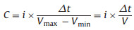
The specific capacitances of half-cells and LIHCs are calculated using the following equation. Cycling stability and rate performance were tested by a battery test system (Land CT2001A model, Wuhan Land Electronics, Ltd). The specific capacitances of halfcells and LIHCs were calculated by equation:
|
The energy and power densities of LIHCs were calculated using the following equations:
|
i is the current energy, Δt is time duration for a full discharge process, Vmax is the voltage at the beginning of discharge, and Vmin is the voltage at the end of discharge. E is the energy density. P is the power density.
The prepared process of NCNTs is described in Fig. 1a, which includes multistep pyrolysis process. At the first temperature of 350 ℃, under this condition the C2H4N4 first condensated into melem skeleton, further through the reaction of ketoamine condensation between Co(acac)2 and melem, forming the bonding of Co-O-N anchored Co on the melem skeleton, which is as precursor of catalyst for constructed the structure of CNTs. when the temperature reached to 650 ℃, it would transform into Co-gC3N4, achieved N-doping and formed Co NPs, which is greatly important to prepare NCNTs as the catalysis for the next step. When the temperature beyond 650 ℃, Co@NCNTs were continuously generating [45]. Finally, removing Co NPs and obtaining the NCNTs. According to our previous research, the level of N-doping decrease as the temperature increase [44]. Therefore, we choose 700 ℃ as the carbonated temperature for NCNTs in order to maintain high-level N-doping and form the structure of high electrical conductivity CNTs [44]. In this typical synthesis method, C2H4N4 was used as carbon and nitrogen sources for carbonaceous skeleton materials, and Co(acac)2 was used as the catalyst for the formation of the one-dimensional NCNTs. It is worth noting that this structure facilitate the ion and charge transfer, which were good at performance of Li-ion storage capacity and rate [17, 36, 40]. Furthermore, the morphologies of NCNTs were characterized by SEM and TEM. As shown in Fig. 1b, the NCNTs exhibit typical uniform open- tubular morphology. From the TEM image of NCNTs (Fig. 1c), the bamboo-shaped carbon nanotubes structure is found. Moreover, the selected area electron diffraction (SAED) pattern (inset of Fig. 1d) confirms that the disordered and amorphous structure of NCNTs, which are suitable for lithium ion adsorption and will bring high performance of LIHCs. In order to match the capacity of NCNTs, we choose high-SSA APDC as cathode materials for LIHCs. The morphology of APDC was shown in Figs. 1d and e exhibiting typical rod morphology, which is similar with NCNTs, considering as benefited to matching performance between anode and cathode materials.

|
Download:
|
| Fig. 1. Schematic illustration showing the the growth of NCNTs (a). (b) SEM and (c) TEM image of NCNTs (inset of (c): SAED pattern). (d) SEM and (e) TEM image of APDC. | |
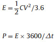
The Raman spectrum shows in Fig. 2a, The D and G peaks at 1355 cm-1 and 1591 cm-1 respectively, the D peak is ascribed to the structural defects of graphitic domains, and the G peak assigned to the large conjugated domains of carbon. Thus, the ID/IG exhibit the disorder degree of the carbon [46-48]. The value of the ID/IG is 1.04 indicating that the NCNTs have highly defective and disordered structure. Moreover, the broad band of the 2D peak from 2500 cm-1 to 3200 cm-1 further confirms the formation of the amorphous structure of NCNTs [44]. The XRD pattern displays a typical diffraction peak at 26.2° corresponding to (002) plane of graphite. Another peaks at 44.3°, 51.2° and 75.6° were observed attribute to (111), (200) and (220) planes of Co NPs (Fig. 2b). The residual Co NPs are difficult to remove because they are compact wrapped into NCNTs [44]. That is normal phenomenon appeared as well as in commercial CNTs, founding some catalyst wrapped into CNTs (Fig. S1 in Supporting information). Furthermore, the ICP result is shown in Table S1. Comparing before and after treated sample, it can be seen that about 93% Co NPs were removed by acid solution. BET SSA and pore size distribution of NCNTs are also studied and shown in Fig. 2c. It can been seen that nitrogen adsorption/desorption isotherm curve belong to a H4 type and the BET surface areas of NCNTs is 205.3 m2/g. The hysteresis loop occurs in the medium and high pressure meaning that there are abundant mesoporous in NCNTs. The pore size distributions shown in Fig. 2d the average pore widen is about 2.6 nm consistenting with the results of Co@NCNTs in Fig. S2 (Supporting information). The XPS of NCNTs are shown in Figs. 2e and f. It can be seen from survey spectra (Fig. 2e) the content N up to 5.58 at% based on XPS shown in Table S2 (Supporting information). The N 1s spectrum (Fig. 2f) was further divided into pyridinic N (398.8 eV) and pyrrolic N (400 eV) [41], which is good at electrochemical performances performance. In addition, NCNTs contained a larger mumber oxygen groups according to XPS. The oxygen groups can not only increase the interlayer intercalation energy storage, but also contribute to energy storage by redox reactions, which is a typical hard carbon charge storage mechanism [49].

|
Download:
|
| Fig. 2. (a) Raman spectrum, (b) XRD pattern, (c) nitrogen adsorption/desorption isotherm curve and (d) pore size distribution of NCNTs. (e) XPS survey spectra and (f) highresolution N 1s spectrum. | |
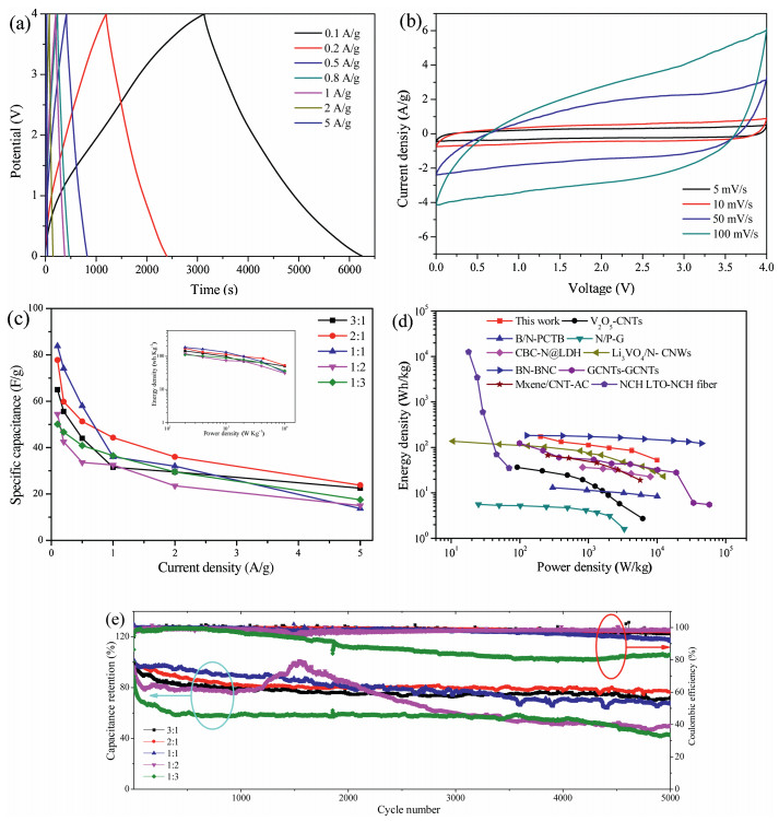
The electrochemical performances of electrodes were characterized by CV and GCD, respectively. Firstly, the anode shows excellent lithium-ion storage performances according to Figs. 3a-c. Fig. 3a shows CV curves of NCNTs at a scan rate of 0.2 mV/s within a potential range of 0.01–3 V (vs. Li/Li+). The broad cathodic peaks locate at 1.50 V and 0.6 V are observed in the first cycle and disappear in the subsequent cycles. This irreversible process associated to the decomposition of electrolyte and the formation of solid-sate interface (SEI) films [50, 51]. According to GCD tests, it can be also seen that the initial discharge process would results the large initial capacity of 1800 mAh/g at the current density of 0.1 A/g shown in Fig. S3 (Supporting information). After that, the discharge specific capacity stabilized at 740 mAh/g at the same current density. The large decrease of the capacity was ascribed to the formation of SEI layer and other side reactions, which is accord with CV curves [52, 53]. Furthermore, the rate capability of the NCNTs reflected in Figs. 3b and c. There is no obvious platform seen in Fig. 3b, that indicated the energy storage is come from the surface double layer capacitance and the inserted pseudocapacitance. The rate capability of the NCNTs under different current densities was shown in Fig. 3c. The specific capacities of NCNTs are from 740 mAh/g to 180 mAh/g at the current rates of 0.1 A/g to 5 A/g, respectively. The NCNTs retain high reversible capacities of 500 mAh/g even at current densities of 1 A/g. The NCNTs exhibit capacitive feature and with high capacity, which is regarded as promising anode for LIHCs. In addition, the EIS of NCNTs electrode is also measured, and Nyquist plots is shown in Fig. S4 (Supporting information). The Nyquist plot consists of a semicircle in the high-medium frequency and a straight line in the low frequency, which are related to the charge transfer resistance and the solid-state diffusion, and indicating that the Li ion intercalation in NCNTs is not limited by the electrical conductivity, that is decided by the diffusion process. Furthermore, the electrochemical performances of Co@NCNTs were given (Fig. S5 in Supporting information). Comparing with Co@NCNTs, NCNTs exhibit good performance. Among that the capability better than Co@NCNTs, but Co@NCNTs play some improve for rate capability. That is because Co metal does not contribute to for capability just added the mass of electrode, but the Co metal good for electrical conductivity, which make the rate capability increase.

|
Download:
|
| Fig. 3. (a) CV curves of NCNTs sample at a sweep rate of 0.2 mV/s. (b) The typical charging/discharging curves of NCNTs electrodes within the potential window of 0.01–3 V (vs. Li/Li+). (c) Rate capability of NCNTs sample at different current densities. | |
For capacitor-type cathode, we choose the APDC prepared by Yan et al. as the activeated materials [17], which exhibit good capacitive characteristics of charge storage in organic electrolytes. The electrochemical performance of APDC was also evaluated by CV and GCD. Fig. 4a shows CV curves of APDC at different scan rates within a potential range of 2–4 V (vs. Li/Li+) in lithium ion half cell. The rate capability of the APDC is reflected in Figs. 4b and c. The specific capacities of APDC are from 74 mAh/g to 40 mAh/g with the current density ranging from 0.1 A/g to 5 A/g. The quasi-rectangular CV curves and linear charge/discharge process at different current densities indicated a good capacitive performance of the APDC, which is indicated the energy storage is come from adsorption of ions on the surface. It is considered to be an ideal cathode material for LIHCs devices.

|
Download:
|
| Fig. 4. (a) CV curves of APDC sample at different sweep rates. (b) The charging/discharging curves of APDC electrodes within the potential window of 2–4 V (vs. Li/Li+). (c) Rate capability of APDC sample at different current densities. | |
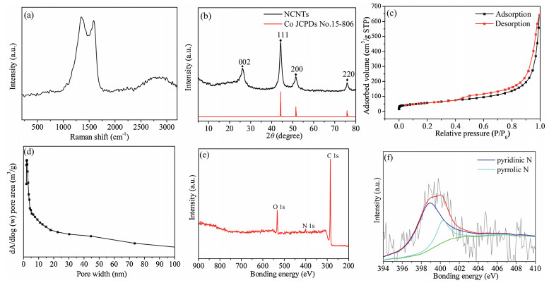
Before assembling a LIHCs device, the NCNTs electrode as a lithium ion half-cell was cycle for 10 times at 100 mA/g and then sodiated to 0.01 V. After that, use pre-lithiumed NCNTs as the anode and APDC as the cathode in 1 mol/L LiPF6 in EC-DMC electrolyte solution. In order to achieve the best performance of LIHCs device, the mass ratio between NCNTs and APDC was optimized. The typical CV curves of NCNTs//APDC with the different mass ratios of 3:1, 2:1, 1:1, 1:2, 1:3 and tested in the potential range of 0–4.0 V as shown in Fig. 5a and Fig. S6(Supporting information). Their CVprofiles exhibit a slight deviation from the ideal rectangular shape because the coupling effect of two different energy-storage mechanisms. Fig. 5b and Fig. S7 (Supporting information) show the GCD curves at different current densities ranging from 0.1 A/g to 5 A/g. Their GCD profiles exhibit approximately linear slope. The specific capacitances of full cells are calculated based on the total mass of active materials in both two electrodes as shown in Fig. 5c and corresponding ragone plot (energy density vs. power density) was shows in inset. That is indicated with the mass radio of 2:1 exhibit the best performance. The LIHCs achieve the maxiumest energy density of 173.3 Wh/kg at power density of 200 W/kg, and still deliver energy density of 52.9 Wh/kg even at an ultra-high power density of 10 kW/kg. NCNTs//APDC full cell with mass ratio of 2:1 also exhibits the best cycling stability and high columbic efficiency with a capacity retention of 80% after 5000 cycles at a high current density of 1 A/g (Fig. 5e).

|
Download:
|
| Fig. 5. (a) Electrochemical performance of NCNTs//APDC LIHCs device. CV curves at the scan rates of 5–100 mV/s. (b) The corresponding GCD profiles with mass ratio of 2:1. (c) Specific capacitances with different mass ratios and corresponding ragone plots. (d) Ragone plots of LIHCs in this work comparing with reported representative LIHCs. (e) Long-term cycle life and Coulombic efficiency of NCNTs//APDC LIHCs with different mass ratios under 1 A/g at 0–4.0 V. | |
To further illustrate the high-energy and high-power feature of this HLIC device, we carry out the comparison of the energy and power densities of the present NCNTs//APDC device using similar carbon tubular morphology as anodes reported previously, the results as shown in Fig. 5d were compared with V2O5-CNTs//AC [36], B/N-PCTB//B/N-PCTB [37], N/P-G//N/P-G [39], CBC-N@LDH//CBC-N2 [35], Li3VO4/N-CNWs//AC [40], BN-BNC//BNC [38], GCNTsGCNTs [54], Mxene/CNT-AC [55] and NCH LTO-NCH fiber [56]. The results confirmed the NCNTs//APDC devices exhibit relatively higher energy and power features compared with state-of-the-art hybrid device.
In summary, we using a facile multistep pyrolysis method to prepare NCNTs and introduced relatively high level N and plenty of oxygen groups. The N-doping increased the wettability and electrochemical active sites, and oxygen groups increased the capacity through amorphous adsorption, which is an ideal structure as anode for LIHCs. The NCNTs shows of excellent performance of specific capacities and rate. That is retained high reversible capacities of 500 mAh/g even at current densities of 1 A/g. By further coupling with the high performance APDC as cathode, the LIHCs device are constructed and showed the excellent properties. To achieve a LIHCs with high energy density and high power density (173 Wh/kg and 10 kW/kg) and outstanding cyclic life (80% capacity retention after 5000 cycles tested at 1.0 A/g within 0–4.0 V). Our results shows that material based on tubular-architecture with high N-doping carbonaceous materials display the high performance, that is as promising anode for promote the development of LIHCs device.
Declaration of competing interestThe authors declare that they have no known competing financial interests or personal relationships that could have appeared to influence the work reported in this paper.
AcknowledgmentsThis work was supported by the Natural Science Foundation of China (No. 21872066) and the Natural Science Foundation of Gansu (No. 18JR3RA274).
Appendix A. Supplementary dataSupplementary material related to this article can be found, in the online version, at doi:https://doi.org/10.1016/j.cclet.2019.11.044.
| [1] |
D. Larcher, J.M. Tarascon, Nat. Chem. 7 (2014) 19. |
| [2] |
X. Han, L. Lu, Y. Zheng, et al., eTransportation 1 (2019) 100005. DOI:10.1016/j.etran.2019.100005 |
| [3] |
Y. Liu, X. He, D. Hanlon, et al., ACS Nano 10 (2016) 5980-5990. DOI:10.1021/acsnano.6b01505 |
| [4] |
D. Sun, J. Chen, J. Yang, et al., CrystEngComm 16 (2014) 10476-10484. DOI:10.1039/C4CE01604A |
| [5] |
D. Sun, X. Yan, J. Yang, et al., ChemElectroChem 2 (2015) 1830-1838. DOI:10.1002/celc.201500145 |
| [6] |
N. Sinan, E. Unur, J. Energy Chem. 26 (2017) 783-789. DOI:10.1016/j.jechem.2017.04.011 |
| [7] |
Y. Ma, H. Chang, M. Zhang, et al., Adv. Mater. 27 (2015) 5296-5308. DOI:10.1002/adma.201501622 |
| [8] |
H. Kim, K.Y. Park, M.Y. Cho, et al., ChemElectroChem 1 (2014) 125-130. DOI:10.1002/celc.201300186 |
| [9] |
R. Wang, J. Lang, Y. Liu, et al., NPG Asia Mater. 7 (2015) e183. DOI:10.1038/am.2015.42 |
| [10] |
J. Lang, X. Zhang, B. Liu, et al., J. Energy Chem. 27 (2018) 43-56. DOI:10.1016/j.jechem.2017.11.020 |
| [11] |
P. Wang, R. Wang, J. Lang, et al., J. Mater. Chem. A 4 (2016) 9760-9766. DOI:10.1039/C6TA02971J |
| [12] |
R. Wang, P. Liu, J. Lang, et al., Energy Storage Mater. 6 (2017) 53-60. DOI:10.1016/j.ensm.2016.10.002 |
| [13] |
E. Lim, H. Kim, C. Jo, et al., ACS Nano 8 (2014) 8968-8978. DOI:10.1021/nn501972w |
| [14] |
S.W. Lee, N. Yabuuchi, B.M. Gallant, et al., Nat. Nanotechnol. 5 (2010) 531-537. DOI:10.1038/nnano.2010.116 |
| [15] |
P. Wang, B. Yang, G. Zhang, et al., Chem. Eng. J. 353 (2018) 453-459. DOI:10.1016/j.cej.2018.07.150 |
| [16] |
B. Yang, J. Chen, S. Lei, et al., Adv. Energy Mater. 8 (2018) 1702409. DOI:10.1002/aenm.201702409 |
| [17] |
R. Wang, J. Lang, P. Zhang, et al., Adv. Funct. Mater. 25 (2015) 2270-2278. DOI:10.1002/adfm.201404472 |
| [18] |
R. Wang, X. Yan, Sci. Rep. 4 (2014) 3712. |
| [19] |
X. Miao, D. Sun, X. Zhou, et al., Chem. Engin. J. 364 (2019) 208-216. DOI:10.1016/j.cej.2019.01.158 |
| [20] |
D. Sun, X. Miao, Y. He, et al., Electrochim. Acta 320 (2019) 134616. DOI:10.1016/j.electacta.2019.134616 |
| [21] |
D. Sui, L. Xu, H. Zhang, et al., Carbon 157 (2020) 656-662. DOI:10.1016/j.carbon.2019.10.106 |
| [22] |
V. Khomenko, E. Raymundo-Piñero, F. Béguin, J. Power Sources 177 (2008) 643-651. DOI:10.1016/j.jpowsour.2007.11.101 |
| [23] |
R. Liu, J. Wang, T. Sun, et al., Nano Lett. 17 (2017) 4240-4247. DOI:10.1021/acs.nanolett.7b01154 |
| [24] |
F. Zhang, T. Zhang, X. Yang, et al., Energy Environ. Sci. 6 (2013) 1623-1632. DOI:10.1039/c3ee40509e |
| [25] |
Y. Ding, B. Yang, J. Chen, et al., Sci. China Mater. 61 (2018) 285-295. |
| [26] |
S. Zhang, C. Li, X. Zhang, et al., ACS Appl. Mater. Interfaces 9 (2017) 17136-17144. DOI:10.1021/acsami.7b03452 |
| [27] |
C. Li, X. Zhang, K. Wang, et al., J. Power Sources 414 (2019) 293-301. DOI:10.1016/j.jpowsour.2018.12.090 |
| [28] |
C. Li, X. Zhang, K. Wang, et al., J. Power Sources 400 (2018) 468-477. DOI:10.1016/j.jpowsour.2018.08.013 |
| [29] |
J. Zhang, J. Wang, Z. Shi, et al., Chin. Chem. Lett. 29 (2018) 620-623. DOI:10.1016/j.cclet.2018.01.031 |
| [30] |
H. Wang, Z. Xu, Z. Li, et al., Nano Lett. 14 (2014) 1987-1994. DOI:10.1021/nl500011d |
| [31] |
T. Zhang, F. Zhang, L. Zhang, et al., Carbon 92 (2015) 106-118. DOI:10.1016/j.carbon.2015.03.032 |
| [32] |
K. Leng, F. Zhang, L. Zhang, et al., Nano Res. 6 (2013) 581-592. DOI:10.1007/s12274-013-0334-6 |
| [33] |
C.-T. Hsieh, D.-Y. Tzou, Y.-C. Chen, et al., Mater. Chem. Phys. 164 (2015) 230-237. DOI:10.1016/j.matchemphys.2015.08.053 |
| [34] |
J.J. Ren, L.W. Su, X. Qin, et al., J. Power Sources 264 (2014) 108-113. DOI:10.1016/j.jpowsour.2014.04.076 |
| [35] |
F. Lai, Y.E. Miao, L. Zuo, et al., Small 12 (2016) 3235-3244. DOI:10.1002/smll.201600412 |
| [36] |
Z. Chen, V. Augustyn, J. Wen, et al., Adv. Mater. 23 (2011) 791-795. DOI:10.1002/adma.201003658 |
| [37] |
J. Zhao, Y. Li, G. Wang, et al., J. Mater. Chem. A 5 (2017) 23085-23093. DOI:10.1039/C7TA07010A |
| [38] |
Q. Xia, H. Yang, M. Wang, et al., Adv. Energy Mater. 7 (2017) 1701336. DOI:10.1002/aenm.201701336 |
| [39] |
Y. Wen, T.E. Rufford, D. Hulicova-Jurcakova, et al., ChemSusChem 9 (2016) 513-520. DOI:10.1002/cssc.201501303 |
| [40] |
L. Shen, H. Lv, S. Chen, et al., Adv. Mater. 29 (2017) 1700142. DOI:10.1002/adma.201700142 |
| [41] |
W. Zhang, C. Xu, C. Ma, et al., Adv. Mater. 29 (2017) 1701677. DOI:10.1002/adma.201701677 |
| [42] |
Y. Deng, Y. Xie, K. Zou, et al., J. Mater. Chem. A 4 (2016) 1144-1173. DOI:10.1039/C5TA08620E |
| [43] |
N.Q. Tran, B.K. Kang, M.H. Woo, et al., ChemSusChem 9 (2016) 2261-2268. DOI:10.1002/cssc.201600668 |
| [44] |
D. Xu, H. Zhao, Z. Dong, et al., ChemCatChem 11 (2019) 1-13. DOI:10.1002/cctc.201801860 |
| [45] |
Y. Cheng, S. Zhao, B. Johannessen, et al., Adv. Mater. 30 (2018) e1706287. DOI:10.1002/adma.201706287 |
| [46] |
J. Yang, X.B. Yan, J.T. Chen, et al., Chin. Chem. Lett. 25 (2014) 375-379. DOI:10.1016/j.cclet.2013.10.031 |
| [47] |
J. Yang, X. Yan, J. Chen, et al., RSC Adv. 2 (2012) 9665-9670. DOI:10.1039/c2ra20948a |
| [48] |
J. Yang, J. Chen, S. Yu, et al., Carbon 48 (2010) 2665-2668. DOI:10.1016/j.carbon.2010.03.037 |
| [49] |
J. Zhao, Y.Z. Zhang, F. Zhang, et al., Adv. Energy Mater. 9 (2019) 1803215. DOI:10.1002/aenm.201803215 |
| [50] |
Z. Zhou, L. Pan, Y. Liu, et al., Chin. Chem. Lett. 30 (2019) 610-617. DOI:10.1016/j.cclet.2018.08.018 |
| [51] |
M. Zhang, R. Liu, Z. Wang, et al., Chin. Chem. Lett. 31 (2020) 1217-1220. DOI:10.1016/j.cclet.2019.07.055 |
| [52] |
L. Su, S. Lei, L. Liu, et al., J. Mater. Chem. A 6 (2018) 9997-10007. DOI:10.1039/C8TA02982B |
| [53] |
R. Wang, J. Lang, P. Zhang, et al., Adv. Funct. Mater. 25 (2015) 2270-2278. DOI:10.1002/adfm.201404472 |
| [54] |
R.V. Salvatierra, D. Zakhidov, J. Sha, et al., ACS Nano 11 (2017) 2724-2733. DOI:10.1021/acsnano.6b07707 |
| [55] |
P. Yu, G. Cao, S. Yi, et al., Nanoscale 10 (2018) 5906-5913. DOI:10.1039/C8NR00380G |
| [56] |
S.N. Kanakaraj, Y.Y. Hsieh, P.K. Adusei, et al., Carbon 149 (2019) 407-418. DOI:10.1016/j.carbon.2019.04.032 |